
Subscribe to Our Youtube Channel
Related Manuals for Kärcher BR 52/11 ESC


Summary of Contents for Kärcher BR 52/11 ESC
- Page 1 Escalator Cleaner English From Serial Number (Ref No1**) **See Serial Number Page or call manufacturer Register 86457880-A 02/09/24 your product www.kaercher.com/welcome...
-
Page 2: Machine Data Label
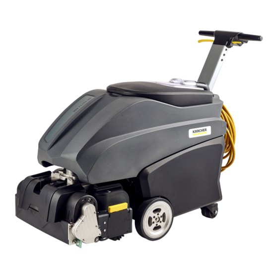
Machine Data Label Overview The new BR 52/11 ESC was designed with simplicity in mind. Maintaining escalators and travelators in any environ- ment can be accomplished ergonomically and efficiently with a single operator. Down time is kept to a minimum, utilizing proper solution flow along with excellent recovery. -
Page 3: Table Of Contents
Table of Contents Machine Data Label ......2 Overview ........2 Table of Contents . - Page 4 How To Use This Manual This manual contains the following sections: The SAFETY section contains important information regarding hazardous or unsafe practices of the • How to Use This Manual machine. Levels of hazards are identified that could • Safety result in product damage, personal injury, or severe •...
-
Page 5: Safety
Safety Grounding Instructions 120 Volt Models: THIS PRODUCT IS FOR COMMERCIAL This appliance is for use on a nominal 120-volt circuit, and has a grounded plug that looks like the plug in "Fig. USE ONLY. A". A temporary adapter that looks like the adapter in Electrical: "Fig. -
Page 6: Important Safety Instructions
Safety Important Safety Instructions When using this machine, basic precaution must always be followed, including the following: READ ALL INSTRUCTIONS BEFORE USING THIS MACHINE. To reduce the risk of fire, electric shock, or injury: Connect to a properly grounded outlet. See Grounding Instructions. Use only as described in this manual. -
Page 7: Hazard Intensity Level
Safety The following symbols are used throughout this guide as indicated in their descriptions: Hazard Intensity Level There are three levels of hazard intensity identified by signal words -WARNING and CAUTION and FOR SAFETY. The level of hazard intensity is determined by the following definitions: WARNING - Hazards or unsafe practices which COULD result in severe personal injury or death. -
Page 8: Operation
Operation How the Machine Works Once the machine enters the cleaning position with power switched on, turn on the start switch in the middle of the control panel to choose one of two cleaning options, “Regular” and “Deep Cleaning”. The Brush Deck starts lowering until the two cylindrical brushes touch the moving treads. - Page 9 Operation ITEM MEASURE Height 952.5 mm Length 1275.5 mm Width 523 mm This appliance is not intended for use by persons (including children) with reduced physical, sensory or mental capabilities, or lack of experience and knowledge, unless they have been given supervision or instruction concerning use of the appliance by a person responsible for their safety.
-
Page 10: Unpacking The Machine
Operations Unpacking the Machine 5. Remove the lid from the crate. The lid will be used as a ramp to safely maneuver the machine off the 1. The crate is marked with a label "Open from this pallet. side". 2. Remove the screws securing this panel of the crate 6. -
Page 11: Components
Operations Components 1. Deck: Dual Brushes, dual motors, dual gearboxes 2. Solution Tank 3. Handle and Control Panel 4. Gear boxes 5. Recovery Tank 6. On-site brush deck cleaning tray 8.645-788.0 Manual Operator Escalator Cleaner... -
Page 12: Before Operating
Operation Important: • Before operating the machine, the operator must Read All Instructions Before Using This Machine. • A “Maintenance in Progress” perimeter sign must be set up at both ends of the escalator. • The operator must know where the Emergency Stop Button is located. •... -
Page 13: Operating The Machine
Operation Operating the Machine • The operator must be able to use the brake so the machine can be positioned accurately for the best cleaning result and avoiding accidental bumping against the steps. • The treads on the escalator must be moving toward the escalator cleaner. Do not operate the machine with the treads moving away from the machine. -
Page 14: Cleaning Tips
Operation Cleaning Tips Wrong Correct Machine positioned at angle with escalator / moving Machine positioned parallel with escalator/moving sidewalk. Decreased cleaning performance, increased sidewalk. likelihood of damage to brushes and machine. Brush not fully engaged in brush housing. Decreased Brush fully engaged in brush housing. cleaning performance 8.645-788.0 Manual Operator Escalator Cleaner... - Page 15 Operation Cleaning Tips - continued: Wrong Correct Rear edge of brushes and brush housing positioned Rear edge of brushes and brush housing positioned partially over escalator/moving sidewalk comb. beyond escalator/moving sidewalk comb, fully over Decreased cleaning performance, higher likelihood of escalator/moving sidewalk landing.
-
Page 16: Maintenance
Maintenance Cleaning or replacing the brushes • Lift the yellow colored latch and slide out the brushes for cleaning or replacing. With the brushes removed, inspect the brush cavity and remove dirt/debris. • Water Filter Unscrew the transparent cap, and remove the filter. Thoroughly clean and rinse to remove accumulated dirt •... -
Page 17: Nozzles & Tray
Maintenance Nozzles & Tray • Turn the nozzles counterclockwise to remove the nozzles for cleaning. • For cleaning the tray, push the quick lock on the right side while holding the other end of the tray to slide it 8.645-788.0 Manual Operator Escalator Cleaner... -
Page 18: Brake Adjustment
Maintenance Brake Adjustment 4. Tighten the knurled screw The brake adjustment cylinder is located at the rear of the machine, just behind the power cord. The same procedure applies for adjusting both left and right brakes: Left Brake Adjusting shown: 1. -
Page 19: Troubleshooting
Maintenance Troubleshooting PROBLEM CAUSE AND SOLUTION Vacuum, pump or brush motor stop Inspect the brushes and brush housing. Any dirt and soil built up may working trigger the overloading protection of the pump or brush motor. Inspect the brushes for signs of wearing or damage to the bristles. Replace worn or damaged brushes.
Need help?
Do you have a question about the BR 52/11 ESC and is the answer not in the manual?
Questions and answers