
Related Manuals for NDT yateks Realta


Summary of Contents for NDT yateks Realta
-
Page 1: Realta 3D Measurement
Realta 3D Measurement Industrial Video Borescope Operating Instructions Warning: Please read the operating manual carefully before using the instrument. -
Page 2: User Instructions
User Instructions Please read the user instructions carefully before operating the instrument. Danger 1. Do not use the instrument to detect human or animals. 2. Do not use or store the device at the places with flammable materials, strong magnetic field, and combustible gas, otherwise it may cause fire or explosion. -
Page 3: Precautions
5. In the event of smoking or abnormal noise, stop using the instrument immediately and cut off the power. 6. Do not look straight at the light from end of the insertion tube, avoiding the strong light affecting your eyesight. 10. - Page 4 a certain direction for a long time, which will put the instrument in a high load state and will affect the service life. 6. Please note the following during the operation of the distal end of the insertion tube: a) Do not crash the front of the insertion tube or drag it by force. b) Do not crash its bending section or bend it excessively.
-
Page 5: Battery Treatment Method
13. Do not store the instrument in the following environments, otherwise it may cause damage to the instrument. a) In an environment with high temperature, high humidity and a lot of dust or particles. b) Where there is direct sunlight or radiation. c) Locations containing halide gases. - Page 6 expose the battery to moisture. Never charge the battery near an open fire or in direct sunlight, otherwise there is a risk of explosion or fire. Do not pierce the battery or make it subjected to strong impact or stress, otherwise there is a risk of explosion or fire. Do not drop or throw the battery or make the battery hit violently.
- Page 7 Keep away from flammable materials during charging, and do not cover the battery charger with flammable materials. Precautions 1. Do not use or store the battery in a high-temperature environment, such as in direct sunlight, in an enclosed car or in front of a heating instrument.
- Page 8 2. The performance of a battery usually deteriorates as the ambient temperature drops. Please note that battery performance, which is reduced by low temperature, can be restored when the temperature rises to normal levels. 3. When batteries run out of life, be sure to recycle them in accordance with local regulations.
-
Page 9: Table Of Contents
Please refer to the real-time information on the official website. Contents REALTA 3D MEASUREMENT ................1 INDUSTRIAL VIDEO BORESCOPE ................ 1 USER INSTRUCTIONS ..................2 PRECAUTIONS ..................3 λ BATTERY TREATMENT METHOD ............5 λ PRODUCT OVERVIEW ............... 10 PARAMETER DEFINITION ..............11 MAIN PERFORMANCE PARAMETERS........ -
Page 10: Product Overview
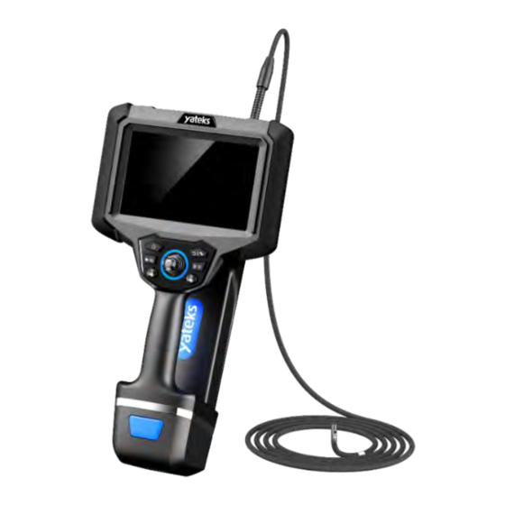
Product Overview The instrument is mainly composed of five parts: camera, insertion tube, host, LCD screen, and operating handle. It is a new type of non-destructive flaw detection instrument integrating optics, precision machinery, electronic machinery, electronic technology, microscopic camera technology. It is often used for the detection of internal surface defects that cannot be touched by the naked eye. -
Page 11: Parameter Definition
directions, realize long-distance image transmission, and can enter deeper pipeline inspections. Adopt general-purpose computing graphics processor technology to make image and video processing algorithms faster and make images clearer and smoother. With measurement function, it can generate 3D point cloud map, depth map, contour map, etc., and reproduce the contour of the measured object. - Page 12 measurement, automatic white balance, image browsing, lock fine-tuning, menu Joystick Electric joystick 360° omni-directional Control camera guidance Guidance Lockable fine-tuning, stepping, fast and Control slow speed adjustment, automatic reset Memory Built-in 128G + extended 64G U disk (up to 256G) Data I/O port 2 USB2.0 host "A"...
- Page 13 Function Digital Zoom Continuous (level 10) Image Control Screen freeze, image flip Image Format JPG, PNG (recording date and time) Video Format AVI, M P4 (recording date and time) Simplified Chinese, English, French, Language Spanish, Russian, Japanese, Korean, Software Traditional Chinese, German, Portuguese Color Settings Near distance, medium distance, far distance, custom color mode White...
-
Page 14: Purpose And Scope Of Application
the text, and can annotate the endoscopic pictures at any time according to the detection situation, which is convenient for later report generation Software Upgrade through the U disk upgrade Upgrade package Lens outer Probe diameter Insertion 1~3 meters tube length Insertion Tungsten alloy steel wire braided 4-layer tube process... -
Page 15: Functions Of Each Part Of The Instrument
and engines. Real-time photography and video recording can be performed, providing indispensable data collection for analyzing equipment usage status and equipment production guarantee. V. Functions of Each Part of the Instrument Figure 6-1 Host... - Page 16 See the table below for the numbered parts in Figure 6-1: serial number name ① Camera ② Insertion Tube ③ Host Key ④ Return/Motor mode Switching Key ⑤ Video Key /Video playback ⑥ Settings/Menu Key ⑦ Left Joystick ⑧ Right Small Joystick ⑨...
-
Page 17: Preparation Before Inspection
⑱ Battery Pack Power Display Button ⑲ Battery Pack Indicator Light ⑳ Type-C Charging Interface Preparation Before Inspection 7.1 Handling of Case Important Before handling the boxes, please check whether there is any abnormality at the handle and buckles of the box. ... - Page 18 Figure 7-1 Case handling Important If the catch is not fully closed, the lid may accidentally open when the case is lifted. Do not kick or move the box. Unboxing Figure 7-2 Take out the instrument from the box Warning ...
- Page 19 instrument to prevent accidents caused by the automatic closing of the cover. Do not operate the main unit in the box to prevent the cover from accidentally closing and pinching your hands or signal lines. Important Place the box horizontally so it remains stable. ...
- Page 20 Figure 7-3 Instrument detachable modules 1) As shown in the figure above, put the main unit horizontally, and fix the handle probe on the main unit with a hexagonal screwdriver. There are 4 screw fixing holes in total. 2) Align the battery pack with the position of the battery pack of the main unit and tighten the clip.
- Page 21 Battery Pack Charging 1) Take out the power adapter and connect it to the Type-C charging interface of the battery pack. 2) Make sure the power cord is connected to the Type-C charging port. 3) Plug the power cord into a power outlet. 4) the green light flashes, it means charging, and when the green light is all on, it means charging is complete.
- Page 22 Check Insertion Tube Check the appearance of the insertion tube 1) Observe the integrity of the outer material of the entire insertion tube and signal wire. 2) Check for loose outer covering material of the insertion tube (not the angled bend). Figure 7-5 Inspect the Insertion Tube Important...
- Page 23 Figure 7-6 Lens cleaning Warning Internal heat generated by electrical components can heat the tip of the insertion tube. Before wiping the lens, please turn off the light source and let it cool down before touching it. Important the lens used, it may damage the optical adapter or the tip of the insertion tube.
- Page 24 place the front of the instrument vertically and lift the operating handle. 7.6 Attaching and Removing Shoulder Straps To hang the instrument on your shoulder, please attach the shoulder strap. Please use the original shoulder strap provided by manufacturer. Figure 7-7 Shoulder strap installation 1) The 4 buckles of the shoulder strap to the 3 fixed positions of the instrument respectively.
- Page 25 Figure 7-8 Shoulder Strap Installation Completed 4) Use the length adjuster to adjust the length of the shoulder strap and hang it on the shoulder. 5) Fix the insertion tube on the instrument with strip Velcro to avoid accidents caused by pipeline suspension. Warning ...
- Page 26 Important When installing or removing the shoulder strap, be careful not to drop the instrument. Do not store the instrument in a hanging position, the shoulder strap may be damaged. Carefully check to ensure that the shoulder strap hook is firmly fixed on the instrument, if the main unit is lifted directly by the shoulder strap, the instrument may fall.
-
Page 27: Basic Operation
Basic Operation VII. 8.1 Start up Press and hold the [On/Off button] on the right side of the top of the instrument , the instrument will start and display real-time images. 8.2 Button and joystick function description Figure 8- 1 Button Map Figure 8- 2 Button Map See the table below for the names and modes of the button numbers in... - Page 28 Figure 8-1 and 8-6 Real-tim System Survey Serial settings Name Method Navigati Number monitori navigati on Mode ng mode on mode ① Long Power On press 3s Return/ motor mode divided ② Return/Motor Short into lock Mode press fine-tunin Switching Key stepping, normal state...
- Page 29 Button Enter Long system press settings Move choose left and ⑤ left and left right right right selection Left Joystick Move up Select up and down point up down down selection and down selection Move choose left and ⑥ left and left right Right...
- Page 30 Figure 8-3 Short press the "Settings/Menu Button" without any operation, the menu bar will be automatically hidden or displayed. Small joystick operation: In real-time monitoring mode, all functions can be adjusted by moving the small joystick up and down. 8.3.1 【Camera Brightness Adjustment】 [ Camera Brightness Adjustment] icon on the screen to adjust the camera brightness, and the brightness level is divided into 1-10 levels.
- Page 31 8.3.4 【Color Mode Adjustment】 Click the [Color Mode Adjustment] icon on the top of the screen to change the color mode. The color mode is divided into four types: original mode, close mode, far mode, and custom mode. In the case of selecting the switch color mode icon custom mode, an edit icon will appear, click the edit icon to enter the color parameter setting interface.
- Page 32 Figure 8-4 8.3.7 【Zoom Function】 Click the [zoom function] icon on the screen to zoom the real-time monitoring interface. The zoom factors are: 1.15, 1.30, 1.45, 1.60, 1.75, 1.90, 2.05, 2.20, 2.35, 2.50. 8.3.8 【Flip Adjustment】 Click [Flip Adjustment] on the top of the screen to flip the real-time monitoring interface, the following four modes: For the actual screen, the default setting.
- Page 33 8.3.10 【Freeze Function】 Touch Operation: Click the [Freeze Function] icon on the screen to freeze and unfreeze the real-time monitoring interface 8.3.11 【White Balance Adjustment】 Click the [White Balance Adjustment] icon on the screen to adjust the white balance on the real-time monitoring interface. The white balance is divided into two modes: automatic white balance and manual white balance.
- Page 34 image and 3D point cloud image. The 3D measurement interface is as follows: Figure 8-5 Icon Name Icon Name Straight Line Reset Distance Measurement Multiline Set Up Length Back to Point to Surface Previous Step (Depth) Image Profile Browsing Save Point to Line measurement Distance...
- Page 35 Screen Touch Click the effective position of the measurement image on the left, cursor will displayed on the corresponding position. The position can be adjusted by moving the virtual joystick up, down, left, and right. Click the "OK" button of the virtual joystick to confirm the selected point.
- Page 36 When adjusting the position, the cursor will move along with it, and a magnified interface will be displayed next to the cursor, which is the magnified area of the picture where the cursor is located. This function allows the operator to select the measurement point more accurately.
- Page 37 two points on the straight line. Figure 8-7 8.4.3 【Point to Surface Distance (Depth)】 This mode is to measure the distance between the point and the straight line. After selecting 4 measuring points in the left image through the point selection operation, the distance between the point and the line will be automatically generated and displayed on the image.
- Page 38 segments composed of multiple points. Select the measurement point in the image on the left, when the number of points is more than 1 point, the sum of the lengths of the line segments composed of these points will be automatically updated on the interface every time a point is selected, and displayed on the interface.
- Page 39 Figure 8-10 8.4.6 【Profile】 This mode is to obtain the depth trend graph of a section on the cloud map relative to the points on the measured object. By selecting 3 measurement points to form a surface, obtain the depth of all points on the surface that intersect the measured object, and use the trend displayed in graphic form.
- Page 40 8.4.10 【Image Browsing】 Click this icon to enter the image browsing interface, where you can view the saved measurement results and the generated point cloud image, original image, and grayscale image, and click the original image for secondary measurement. Click on the icon to enter the image browsing interface, click on the relevant folder to view the saved measurement results as well as the generated point cloud, original map, and grey scale map, you can click on the original image for the second measurement, you...
- Page 41 Step 2: Click on the folder of 3D measurement images you want to export, and enter the folder, such as shown in the figure below: Step 3: Click on the image you want to export the report as shown below: Step 4: Click on the bottom right corner from the second icon on the right to export the report, as follows:...
- Page 42 8.4.11 【Set Up】 Click on the icon to enter the setting interface, you can set the unit of measurement, divided into mm(mm) and inch (inch), you can set whether to hide/display the depth map on the left image, and you can set the function of displaying the full-screen 3D map.
- Page 43 Figure 8-12 If you cannot get precise result, please follow the below instructions for troubleshooting 1) Bring the endoscope as close to the object as possible so that the object shows on the full screen. 2) When selecting measure points, try to select areas with high point cloud density.
- Page 44 Figure 8-13 up the menu with your finger to switch to the second page menu (as shown in Figure 8-14): Figure 8-14 Swipe right on the menu button to switch to the first page menu. 8.4.14 【Language】 Click the [Language] icon on the main interface of the system settings to enter the language settings (as shown in Figure 8-15):...
- Page 45 Figure 8-15 Ten languages (Chinese, English, French, German, Korean, Portuguese, Russian, Traditional Chinese, Japanese and Spanish) are available, click the button of the corresponding language to switch, click the [Cancel] button to exit the language setting interface. 8.4.15 【Time】 [Time] icon on the main interface of the system setting to enter the time setting (as shown in Figure 8-16): Figure 8-16 The time setting is divided into three formats: European (EU),...
- Page 46 8.4.16 【Video Format】 Click the [Video Format] icon on the main interface of the system settings to enter the video format settings (as shown in Figure 8-17): Figure 8-17 Video format: Set the file format for saving the video after recording the video, divided into AVI and MP4.
- Page 47 8.4.18 【SD Card Management】 On the main interface of the system settings, click the [SD card management] icon to format the SD card, click [OK] to format the SD card, and click [Cancel] to exit the SD card format (as shown in Figure 8-19): Figure 8-19 8.4.19 【Software Update】...
- Page 48 User Tip Do not cut off the power when the instrument software is updated. Please pay attention to keep the battery fully charged during the update. 8.4.20 【Annotation settings】 Click the [Comment Settings] icon on the main interface of the system settings to enter the settings of image annotation, video annotation, and image dwell time (as shown in Figure 8-21): Figure 8-21...
- Page 49 Video Annotation: You can choose whether to make video annotation before video recording. 1)If it is set to "YES", the comment box will pop up before shooting the video, and after commenting, the video will have a comment watermark throughout. 2)If it is set to "NO", the comment box will not pop up before shooting the video.
- Page 50 Figure 8-22 8.4.22 【WIFI Settings】 select "On" and confirm the WIFI settings (as shown in Figure 8-23): Figure 8-23 the WIFI function is turned on, it will return to the implementation monitoring screen. At this time, the endoscope host has turned on the WIFI hotspot and displays the icon.
- Page 51 8.4.23 【Camera Temperature Setting】(optional feature) Click the [Camera Temperature Setting] icon on the main interface of the system settings to set the camera temperature (as shown in Figure 8-24): Figure 8-24 The camera temperature setting includes setting whether to display the temperature unit, and the temperature unit is ℃...
- Page 52 Figure 8-25 Enter the camera angle setting, you can choose 850, 700, 650, and 3 angle values, you can also customize the angle value, click confirm to set successfully. The joystick movement speed can be set to "fast" or "slow”. Adjustment of the speed must be set at the same time as the angle value.
- Page 53 a prompt for infrared light source on the main interface. Important The light source setting requires the corresponding camera support, please pay attention to the model selection, [Light source setting] needs to quickly click [WIFI setting] 10 times to display or hide this function.
- Page 54 Figure 8-28 8.5 Image Browsing Image browsing interface (as shown in Figure 8-29): Figure 8-29 Click [Create Folder] to create a new folder, enter the folder name, and click Save to create a new folder to complete (as shown in Figure 8-30):...
- Page 55 Figure 8-30 8.5.1 【Folder Management】 Click [Folder Management File] to enter the management operation mode, and click [Finish] to exit the folder management mode (as shown in Figure 8-31): Figure 8-31 Click [Rename] to rename the folder (as shown in Figure 8-32):...
- Page 56 Figure 8-32 Click [OK] to complete the folder renaming. Click [Delete] to delete the current folder (as shown in Figure 8-33): Figure 8-33 Click [Set Default Path] to set the current folder as the default folder. After setting as the default folder, the photos and recorded videos will be saved in this folder.
- Page 57 Pictures/videos will be stored in the default folder first. The host is connected to the computer to read the data, and the contents in the SD card folder can be deleted and copied on the computer. 8.5.2 【Photo and Video Browsing】 When the file is not in the folder management mode, click [folder] to browse the pictures and videos in the folder (as shown in Figure 8-34): Figure 8-34...
- Page 58 Figure 8-36 Click the zoom icon to zoom in on the picture. Click on the zoom out icon for a reduced view of the enlarged image. Click the forward and back icons to browse the previous picture and the next picture. Click the delete icon to delete the current picture.
- Page 59 Figure 8-38 Click the text editing icon to add a text watermark to the picture (as shown in Figure 8-39): Figure 8-39 Click the measurement icon to measure the picture (as shown in Figure 8-40):...
- Page 60 Figure 8-40 1)First select the position of the reference object in the picture by touching (the red line in the middle of Figure 8-40), The reference value refers to the data of this part that you already know, if you don't know any dimensions of the objects in the image, this function won't work.
- Page 61 Click the undo icon to undo all the effects of the current edit and return to the original picture state. Click the exit icon to exit the picture editing mode. Click the thumbnail of the video file to view the video (as shown in Figure 8-42): Figure 8-42 Click the play button in the middle to start playing the video, drag the...
- Page 62 This instrument uses a resistive touch screen, which can also be used in harsh environments. Operations on the host interface (such as taking pictures, video recordings, etc.) can be performed with fingers or touch pens. Important: Do not use sharp objects to press the touch screen. The touch pressure should not be greater than 120g.
- Page 63 Figure 8 - 43 host connected to the display 8.7 Steering line handling guide 8.7.1 【Check the Angle Bend Function】 1) Straighten the insertion tube. 2) Slowly operate the rocker in the operating handle to ensure that the angled section moves smoothly. User Tip The angle bending action corresponds to the angle and direction of the joystick action.
- Page 64 the observation angle, stand still for 3 seconds, and the direction will be automatically locked. 4) If you want to reset the lens, just move the joystick arbitrarily and release it, and the lens will automatically reset. 8.7.3 【Fine-Tuning Mode】 1)...
- Page 65 8.7.4 【Stepping Mode】 1) Press the " Return/Motor Mode Switching Key " button directly , the display prompts to step mode. 2) After entering the stepping mode, the steering will automatically straighten the steering position. 3) Move the rocker up and down, the bending direction will be synchronized with the rocker, and the angle is still locked even when the rocker is released.
- Page 66 Figure 8-45 3) Turn the optical adapter nut clockwise until the first turn passes through the connecting threads. Figure 8-46 4) Once through the first thread, turn the entire optical adapter body clockwise while gently pushing the end of the insertion tube into place and no further turns.
- Page 67 Hold the operating handle and insertion tube 1) When the rocker is working, the operation can be completed by pressing the thumb. 2) Other buttons can be operated by pressing and holding the thumb. Figure 8 -48 handle operation ...
- Page 68 User Tip 1) If the bending control mechanism stops its function, or if any abnormality is found during the operation of the instrument, please stop using it immediately. Release the joystick to the auto-zero (central) position and carefully withdraw the insertion tube from the observation.
-
Page 69: Instrument Storage And Maintenance
In a short time after use in a high-temperature environment, the temperature at the front end of the insertion tube becomes high, and it can be used after cooling down. If the insertion tube is abnormal during the removal process, please turn the rocker lightly to remove it, do not use too much force to avoid damage. - Page 70 Do not collide with other objects when storing, handle it with care and use it safely. When not in use for a long time, the function of the instrument should be checked regularly. Warning Keep the instrument out of the reach of children and use it only after you are familiar with the rules of use.
- Page 71 order. Insertion tubes may be damaged if not stored in the correct order. 2) When putting the insertion tube into the box, please handle it with care, otherwise the insertion tube will be damaged. 3) Store the insertion tube so that it does not become bent. 4) Please lock the buckle of the case correctly.
-
Page 72: Troubleshooting
excessive force, otherwise a break in the signal wire may result in a risk of fire or electric shock. Important 1) Do not store the instrument in places with high temperature, high humidity, excessive dust or fine particles, direct sunlight, or discharge of radioactive substances, otherwise the instrument may be damaged. - Page 73 10.1 【Troubleshooting Guide】 Fault Possible reason Recommended Action Press and hold the "host switch" for 6 seconds to The system Operation freezes cannot be turned frequently shut down and restart; pull off. out the battery and restart It can be played by using the VLC media player video playback It can’t play the video...
- Page 74 dirty. The operating handle has a Motor Noise It is normal. "squeak" sound The load is more and more Stretch the insert tube as Bending control motor strenuous when far as possible to reduce overloads. the bending is the looping amount. manipulated Move the joystick arbitrarily to release the angle...
- Page 75 Poor Color The white balance readjust white balance Reproduction setting is wrong. When the Battery Power monitoring is Ignore it, wait a few is Sufficient, the wrong seconds and it will Low Battery disappear Warning Will Pop Video Recording SD card is not in Format the SD card once, Can't Be Closed, FAT32 format.
-
Page 76: External Standards
Yateks and its authorized agencies. Warning Yateks doesn’t have any responsibility for any hurt or damage caused by the repair other than those made by Yateks External Standards Low Voltage Directive Conforms and EMC Directive to CE Compliant WEEE Directive with WEEE RoHS RoHS Directive...
Need help?
Do you have a question about the yateks Realta and is the answer not in the manual?
Questions and answers