
Related Manuals for NDT V-E-400


Summary of Contents for NDT V-E-400
- Page 1 V-E-400 Emodumeter Operator’s Manual Original Instructions: Revision February 2017...
- Page 3 Notice The James Instruments Emodumeter ™ has been tested in accordance with the EU regulations governing Electro-Magnetic compliance and it meets required directives. Emodumeter™ is a registered trademark of James Instruments Inc. and is property of its respective owner. © 2017 James Instruments Inc. All rights reserved. No part of this publication may be reproduced, stored in a retrieval system, or transmitted, in any form, or by any means, mechanical, electronic, photocopying, recording, or otherwise, without prior written permission of...
-
Page 4: Table Of Contents
Contents Table of Contents Introduction ..................1 Instrument Contents List ..............2 Contents List ................3 Testing Bench Contents List ............4 Contents List ................4 Emodumeter Overview ..............6 Control Panel Buttons.............. 7 Menu Layout..................8 Emodumeter Run Mode ..............9 Emodumeter Setup Menus ............ - Page 5 Contents Connecting the Emodumeter ............43 Overview of Menus ................ 44 Setup Menu ................44 Selection Menu ..............46 Review Menu ................. 47 Upload Menu ................. 48 FFT Menu ................50 Tips and Troubleshooting ............... 51 Sampling Frequency and frequency resolution ..... 51 Contact accelerometer ............
- Page 6 In accordance with the following Directive(s): 2006/95/EC Low Voltage Directive hereby declare that: Equipment Emodumeter Model Number V-E-400 is in conformity with the applicable requirements of the following documents Ref. No. Title Edition/date ASTM C 215 Standard Test Method for Fundamental...
-
Page 7: Introduction
Introduction Introduction The Resonant Frequency Tester may be used in the laboratory for research purposes or in the field to assess quality control and concrete stiffness evolution or the damage induced by freezing and thawing of concrete. It is a non-destructive method to determine the longitudinal, torsional, and flexural or transverse resonant frequencies of a variety of materials. -
Page 8: Instrument Contents List
Instrument Contents List Instrument Contents List Each Emodumeter comes with the following items included in the carrying case. Figure 1: Emodumeter Contents 2 www.ndtjames.com... -
Page 9: Contents List
Testing Bench Contents List Contents List Item # Description Case – Used for carrying the Emodumeter and accessories. Emodumeter Instrument – Resonant Frequency Tester encased in a durable protective case. Instruction Manual – Operating instructions for Emodumeter. AC Power Adapter – Used to power the Emodumeter and recharge the unit. -
Page 10: Testing Bench Contents List
Testing Bench Contents List Testing Bench Contents List Each Emodumeter comes with a testing bench which has the following items included. Figure 2: Testing Bench Contents Contents List 4 www.ndtjames.com... - Page 11 Testing Bench Contents List Item # Description Emodumeter Test Bench – Base for performing tests. Flexural Spacer Assembly – Base, #2 and #3. Torsion Block (#3) – Used with Items 9 and/or 12. Rubber Cushions – 4”. Mounting Bolts – Slide on Mounting Rod. Sensor Mounting Rod –...
-
Page 12: Emodumeter Overview
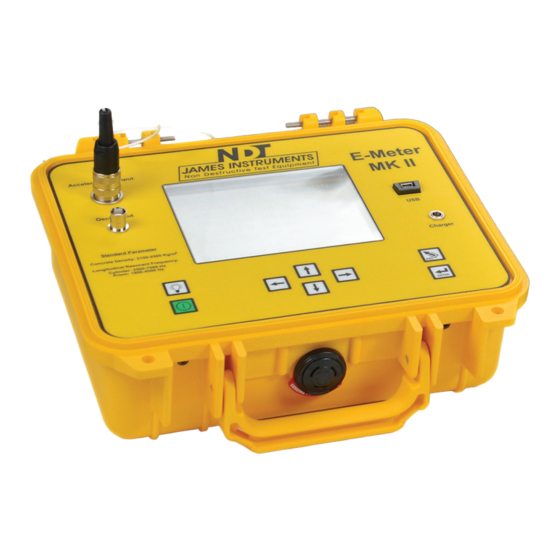
Emodumeter Overview Emodumeter Overview The following is an overview of all of the external features of the Emodumeter. Figure 3: Emodumeter Overview 6 www.ndtjames.com... -
Page 13: Control Panel Buttons
Emodumeter Overview Control Panel Buttons Definition The power button. Momentarily push this key to turn on the unit. Pressing it again turns off the unit. The unit will power up displaying the main menu screen. The up arrow. This key is used to scroll through various settings, wave frames and allows to increase input values needed for calculations. -
Page 14: Menu Layout
Menu Layout Menu Layout Figure 4: Emodumeter Function Flow Chart 8 www.ndtjames.com... -
Page 15: Emodumeter Run Mode
Emodumeter Run Mode Emodumeter Run Mode In order to run the Emodumeter, you need to press the right or left arrow key. The message will change from “Run enable is OFF” to “Run enable is On”. After the system is in the “Run enable is On” mode, the unit will trigger with the impact of the hardened steel ball on the surface of the sample. -
Page 16: Emodumeter Setup Menus
Emodumeter Setup Menus Emodumeter Setup Menus By pressing the “Enter” key, the user will be able to change the testing parameters. The first option is the testing Mode. The user can select Longitudinal (E), Transverse (E) or Torsional (G) by using the left and right arrow keys. -
Page 17: Emodumeter Selections
Emodumeter Selections Emodumeter Selections The Emodumeter selection menu allows the user to select the parameters for testing according to their needs. The Amplifier Gain and Sample Rate can be adjusted to the user needs. The Sample Size or number of data points recorded can be selected from 1024 to 2048 points. -
Page 18: Trigger Level
Emodumeter Selections 1024 points 2048 points 80 kHz 78.1 Hz 39.1 Hz 40 kHz 39.1 Hz 19.5 Hz 20 kHz 19.5 Hz 9.8 Hz 10 kHz 9.8 Hz 4.9 Hz Figure 6: Frequency resolution for each combination of sampling frequency and number of points Maximum Frequency (kHz) -
Page 19: Review Menu
Review Menu Review Menu The review menu allows the user to review previously recorded test results. All the results and parameters used in the test are presented in this menu. The user can review the FFT or the time domain signal as well. www.ndtjames.com 13... -
Page 20: System Setup
System Setup System Setup The System Menu option on the main menu screen allows the user to make modifications of the system configuration. The user can change the date on the instrument, erase data or change the display colors. It also, allows monitoring the battery operation. The Emodumeter can only be set to use the English language. - Page 21 System Setup Figure 9: Hour= [1 PM ] • Press the right or left arrow keys to set the proper hour, press the down arrow key when hour has been set. Minute= [ 0 ] • Press the right or left arrow keys to set the proper minute, press the down arrow key when minute has been set.
-
Page 22: Erase Memory
System Setup Figure 10: Press “Enter” to save date and time. Then press enter to return you to the main menu screen. Erase Memory • Press the up or down key until you get to the system setup menu option. Press Enter. The Setup Menu sub screen should appear. •... -
Page 23: Display Cursor
System Setup • Press enter once and a message telling you to press enter again should appear. Figure 12: • Pressing enter again will erase all stored memory in the Emodumeter. Pressing the “Escape” key will return you to the Main Menu Screen. -
Page 24: Battery Operation
Battery Operation Figure 13: • Pressing the “Escape” key will return you to the Main Menu Screen. Battery Operation ® The Rebarscope uses a 14.4V Lithium-Ion battery with a built-in thermo-sensing circuit. This circuit allows for a suitable charge, and maintains the voltage to the cells (< 4.1V). Additionally, this circuit provides the proper charge current to lengthen the battery’s life. -
Page 25: Battery Charge
Battery Operation microcontroller times out - display and unit turn OFF automatically. Figure 14: Battery Operation Menu is Highlighted -- BATTERY STATUS-- DISCHARGE CTR = xxxx CHARGE CTR = xxxx DCR EXT = 0 CCR EXT = 0 Hit ENT to Clear Reg BATTERY = 100% Figure 15: Clearing Charger Register Battery Charge... -
Page 26: Simple Guidelines For Battery Maintenance
Battery Operation this, go to: Main Menu / System Menu / Battery Operation - press “Enter” to zero the counters. This action also resets the battery circuit mentioned above, and will correct any miscounts. (If charging is still an issue, review the Repair Policy on p.61.) Resetting the battery counters should be done both before and after (at least) a 4hr charge. -
Page 27: Upload Menu
Upload Menu 6. Charge the battery at a moderate temperature. Do not charge below 0deg C (or < 32deg F). 7. Lithium-Ion batteries suffer from stress when exposed to heat. Therefore, to lengthen the life of the battery, avoid elevated temperatures > 30deg C (or > 86deg F). 8. -
Page 28: Test Bench
Test Bench Ctrl + U, the message “Please start Upload” will appear on your PC screen. Then on the Emodumeter unit, press enter on the selected Test and the upload process will begin. You can choose to upload all of the tests stored in memory to the PC, or upload each test one by one. -
Page 29: Accelerometer
Accelerometer Accelerometer The accelerometer is used to sense the vibrations of the specimen caused by the impact of a hardened steel ball. In order for the accelerometer to receive the vibrations, it should be in intimate contact with the surface of the specimen. The sensing front of the accelerometer should be touching the specimen. - Page 30 Testing Procedure Another option is to attach the accelerometer to the surface of the specimen without using the accelerometer support. It can be attached to the specimen using an adhesive mounting base. Wax is usually provided with the system to attach the accelerometer on the surface of the specimen (as shown in Fig.
-
Page 31: Testing Procedure
Testing Procedure Testing Procedure From the Main menu you can choose among 3 different test modes (or methods): • Longitudinal frequency (E) • Transverse frequency (E) • Torsional (G) Longitudinal Frequency Mode The Longitudinal Frequency mode is selected by placing the cursor on the first line, and pressing ‘Enter’. - Page 32 Testing Procedure The system will calculate the dynamic Young’s Modulus of elasticity according to eq. (i), using obtained and computed parameters: M= mass of the specimen (kg) n’= fundamental longitudinal frequency (Hz.) D= 5.093 (L/d²) for a cylinder (N s ² /(kg m² )) or D= 4 (L/bt) for a prism (N s ²...
- Page 33 Testing Procedure Figure 21: Testing for longitudinal resonance frequency Place the accelerometer on the required location (contact point at the center of the face), intimate contact between accelerometer and specimen is required. For the ends of the specimens to be free to vibrate in a longitudinal direction, it is essential that minimum restraint is imposed on the ends.
- Page 34 Testing Procedure In order to obtain the spectrum of the signal and the resonance frequency, the Enter key should be pressed. On the screen will appear the message “calculating spectrum please wait”. It will take approximately 45 seconds. The system will show the fundamental frequency from the FFT, frequency value of the maximum amplitude on the FFT.
-
Page 35: Transverse Frequency Mode
Testing Procedure Mu= E/(2G) – 1 (ii) (E): Dynamic Young’s Modulus of elasticity (obtained according eq. (i)) (G): Dynamic modulus of rigidity (input by the user, the recommended value of (G) is the obtained in a previous Torsional test). Transverse Frequency Mode In order to obtain the elastic constant of the specimen in the transverse or flexural mode, the user should input some data. - Page 36 Testing Procedure Figure 23: Transverse resonance frequency testing setup The accelerometer can be placed using the accelerometer support or by placing a spot of wax on the underside of the surface mounting accelerometer onto the top surface at the middle of the specimen.
- Page 37 Testing Procedure Values of correction factor, T Mu=017 Mu=0.20 Mu=0.23 Mu=0.26 0.01 1.01 1.01 1.01 1.01 0.02 1.03 1.03 1.03 1.03 0.03 1.07 1.07 1.07 1.07 0.04 1.13 1.13 1.13 1.14 0.05 1.21 1.21 0.06 1.28 1.28 1.29 1.29 0.07 1.38 1.38 1.39...
-
Page 38: Torsional Frequency Mode
Testing Procedure Size of the specimen Approximate range (inches) of Frequency (Hz.) 6” x 6” x 30” 550 – 1050 6” x 6” x 28” 600 – 1150 4” x 4” x 36” 400 – 750 4” x 4” x 20” 900 –... - Page 39 Testing Procedure from the FFT (frequency value of the maximum Amplitude on the FFT), which is applied to a time domain signal obtained by slightly tapping the cylinder with a small hardened steel ball. The configuration of the test varies according to the shape of the specimen.
- Page 40 Testing Procedure order to obtain meaningful results, it is recommended to run before a Longitudinal or Flexural test to obtain a value of (E) and then input this value as a parameter to compute the Poisson’s ratio. Mu= E/(2G) – 1 (ii) (G): Dynamic modulus of rigidity (obtained according eq.
-
Page 41: Emodulinx Introduction
Emodulinx Introduction Emodulinx Introduction The Emodumeter’s Emodulinx software enables the user to upload data from the Emodumeter device to a PC. The saved data can be read in and graphed. Emodulinx also can be used to control the Emodumeter remotely. Configuration settings can be adjusted, and new data sets can be collected, all remotely. -
Page 42: Emodulinx Overview
Emodulinx Overview The following is an overview of all of the features of the Emodulinx software. Notice that mostly all menus and settings are the same as the ones found in the Emodumeters menus and settings. Consequently, the same basic operation and testing procedure mentioned earlier in this manual will be used for Emodulinx. -
Page 43: Menu Descriptions
Menu Descriptions Name Description Setup Use this menu to specify the type of test to be performed and shape of the concrete sample (see page 10). Selection Use this menu to select the testing parameters (see page 11-12). Review Use this menu to review previously recorded test results (see page 13). -
Page 44: Software Installation
Software Installation The PC software that has been developed for the Emodumeter is for data upload purposes. To install the software on your PC follow these instructions. To install the software: 1. Insert the Emodumeter PC Software CD into the CD-ROM drive. - Page 45 3. The InstallShield Wizard checks for the operating system you are using. Figure 31: InstallShield Wizard 4. The InstallShield Wizard dialog appears. Click Next to proceed. Figure 32: InstallShield Wizard www.ndtjames.com 39...
- Page 46 5. Accept the terms in the license agreement and click Next. Figure 33: License Agreement Screen 6. Complete the customer information fields and click Next. Figure 34: Customer Information Screen 40 www.ndtjames.com...
- Page 47 7. The InstallShield Wizard confirms your installation. Click Install to continue. Figure 35: InstallShield Wizard Confirmation 8. The installation progress screen appears. Figure 36: Installation Progress Screen www.ndtjames.com 41...
- Page 48 9. When the installation has completed the following message will appear. Click Finish to close the dialog. Figure 37: InstallShield Wizard Completed 10. The Emodulinx shortcut appears on the desktop as well as the Start Menu. Figure 38: Emodulinx Shortcut 42 www.ndtjames.com...
-
Page 49: Connecting The Emodumeter
Connecting the Emodumeter To run Emodulinx, it is required for the Emodumeter to be connected to the PC via the USB cable. Before running Emodulinx, connect one end of the USB cable to the PC and the other end to the Emodumeter. -
Page 50: Overview Of Menus
Overview of Menus Setup Menu Figure 39: Emodulinx Setup Mode Select the radio button of the type of test you wish to perform. Shape Select the radio button that best describes the shape of the concrete sample that you wish to test. Mass Specify the mass of the specimen here. - Page 51 Length Specify the length of the specimen here. Diameter (Cylindrical Only) Specify the diameter of the specimen here. Mu (Transverse E Only) Specify the Dynamic Poisson’s Ratio here (default is .17). b>a, a<b (Prismatic Torsional G Only) Specify the cross-sectional dimensions of the prism, where “a” is less than “b”.
-
Page 52: Selection Menu
Selection Menu Figure 40: Selection Menu Amplifier Gain Use this setting to amplify the received signal. See Tips and Troubleshooting for more information (page 51). Sample Rate Use this setting to adjust the sampling frequency. Sample Size Use this setting to specify the number of data points sampled. Trigger Level Use this setting to adjust the vibration sensitivity of the accelerometer. -
Page 53: Review Menu
Review Menu Figure 41: Review Menu Review Number Adjust this number to upload a summary of a given test, 1 being the first test that is stored on the Emodumeter. Upload Review Click this button after changing the review number to refresh the display window with a review of that particular test. -
Page 54: Upload Menu
Upload Menu Figure 42: Upload Menu Test Number Adjust this number to upload all data of a given test, 1 being the first test that is stored on the Emodumeter. Upload Test Click this button after changing the test number to upload the stored data of that particular test. - Page 55 Upload All Tests Click this to upload all stored tests on the Emodumeter. Save All Tests Click this to save all tests from the “Upload All Tests” operation to your PC. www.ndtjames.com 49...
-
Page 56: Fft Menu
FFT Menu Figure 43: FFT Menu Run Enable Check this box right before you are ready to test so the device can begin gathering data. After performing the test, the FFT graph eventually displays in Emodulinx. Save FFT Click here to save the current FFT data to your PC. 50 www.ndtjames.com... -
Page 57: Tips And Troubleshooting
Tips and Troubleshooting In this section, some of the problems that could arise with the use of the instrument are mentioned as well as recommendations for solving each of them are described. Sampling Frequency and frequency resolution The sampling frequency and the number of collected points will affect the accuracy and precision of your results. -
Page 58: Missing Drivers (Emodulinx)
If you select a high gain, the amplitude will get cut-off at higher amplitude values (as presented in Fig. 44) and the obtained frequency result will be different than the actual value. The gain should be selected in order to obtain the best view in the screen of the entire amplitude of the waveform (as presented in Fig. - Page 59 recognizing the Emodumeter while plugged in. If your Emodulinx software brings up a “Emodumeter Not Found” dialog box upon launch, first make sure the USB cable is firmly plugged in (you will hear a click) and make sure the Emodumeter is turned on. If the dialog box still appears, follow these steps: 1.
-
Page 60: Safety
Figure 46: Device Manager Safety Do not submerge unit in water. This can cause electrical shock. 54 www.ndtjames.com... -
Page 61: Specifications
Specifications Emodumeter V-E-400 Frequency Range from 10 Hz to 40 kHz Sampling Frequency 10, 20, 40 or 80 kHz Frequency Resolution from 4.9 to 78.1 Hz Record Length 1024 or 2048 points Output Bias Level 9.2 V Accelerometer Sensitivity 9.60 mV/g (0.979 mV/m/s2) Battery 14.4 Volt. -
Page 62: Warranty Information
Warranty Information 1. Contract Unless otherwise stated all sales transactions are expressly subject to these terms and conditions. Modification or additions will be recognized only if accepted in writing by an authorized Officer of James Instruments Inc. (hereinafter referred to as “James” or the “Company”), or an officially designated representative. - Page 63 Excluded from the new equipment warranty are all consumable and wear and tear items such as impact bodies, penetrators, connection cables, etc. These items are subject to usual wear and tear during usage. Refer to the Consumable, Wear and Tear Items section of this warranty document.
- Page 64 iv. For Consumables, Wear and Tear Items James supplies consumable items and items subject to wear and tear during normal usage of James supplied products. These items are not covered under warranty. Buyer is to check for proper fit, form and function of such items upon receipt of such items.
- Page 65 c. Warranty Claims i. For Warranty Claim Processing James has established James organizations in the Americas, and Europe. Please visit the James web site www.ndtjames.com latest address contact information for the James organization nearest you. 3. Regulatory Laws and/or Standards The performance of the parties hereto is subject to the applicable laws of the United States.
- Page 66 7. Governing Law This Agreement shall be governed by and construed in accordance with the internal laws of the State of Illinois, without regard to its conflict of laws provisions. Buyer and the Company expressly agree to submit to the personal jurisdiction of the federal and/or stale courts silting in Chicago, Illinois, U.S.A.
-
Page 67: Repair Policy
Repair Policy United States | Canada | International Ship the instrument in a box that meets UPS, Fed Ex, and standard shipping regulations. Enclose a note describing the problem(s) you are having. Include the name and phone number of the contact person in your organization. - Page 68 James Instruments Inc. 3727 N.Kedzie Chicago, IL 60618-4503 Tel: (773) 463-6565 Fax: (773) 463-0009 James Instruments Inc. - Europe Windmolen 22 7609 NN Almelo The Netherlands Tel: +31 (0)548 659032 Fax: +31 (0)548 659010 62 www.ndtjames.com...
Need help?
Do you have a question about the V-E-400 and is the answer not in the manual?
Questions and answers