Sign In
Upload
Manuals
Brands
MR Manuals
Industrial Equipment
VACUTAP VV
MR VACUTAP VV Manuals
Manuals and User Guides for MR VACUTAP VV. We have
2
MR VACUTAP VV manuals available for free PDF download: Installation And Commissioning Instructions
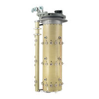
MR VACUTAP VV Installation And Commissioning Instructions (198 pages)
On-load tap-changer
Brand:
MR
| Category:
Industrial Equipment
| Size: 14 MB
Table of Contents
Table of Contents
3
1 Introduction
7
Manufacturer
7
Completeness
7
Safekeeping
7
Notation Conventions
7
Hazard Communication System
7
Information System
9
Instruction System
9
2 Safety
11
Appropriate Use
11
Inappropriate Use
12
Fundamental Safety Instructions
12
Personal Protective Equipment
14
Personnel Qualification
15
3 Product Description
16
Scope of Delivery
16
On-Load Tap-Changer
16
Function Description
16
Setup/Models
17
Nameplate and Serial Number
20
Protective Devices
20
Drive Shaft
26
Function Description
26
Design/Versions
27
4 Packaging, Transport and Storage
32
Packaging
32
Suitability
32
Markings
33
Transportation, Receipt and Handling of Shipments
33
Storage of Shipments
34
Unpacking Shipments and Checking for Transportation Damages
35
5 Mounting
36
Preparatory Work
36
Fitting Mounting Flange on Transformer Cover
36
Fitting Stud Bolts on Mounting Flange
37
Installing the On-Load Tap-Changer in the Transformer (Standard Version)
37
Fastening On-Load Tap-Changer to Transformer Cover
37
Connecting the Tap Winding and On-Load Tap-Changer Take-Off Lead
45
Performing Transformer Ratio Test before Drying
46
Performing DC Resistance Measurement on Transformer
47
Drying On-Load Tap-Changer in Autoclave
47
Drying On-Load Tap-Changer in Transformer Tank
54
Filling the Oil Compartment of the On-Load Tap-Changer with Insulating Fluid
57
Performing Transformer Ratio Test after Drying
58
Installing On-Load Tap-Changer in Transformer (Bell-Type Tank Version)
59
Inserting On-Load Tap-Changer into Supporting Structure
59
Connecting the Tap Winding and On-Load Tap-Changer Take-Off Lead
60
Performing Transformer Ratio Test before Drying
61
Performing DC Resistance Measurement on Transformer
62
Drying On-Load Tap-Changer in Autoclave
62
Lifting Top Part of On-Load Tap-Changer Head off Supporting Flange (Bottom Part)
69
Attaching the Bell-Type Tank and Connecting the On-Load Tap-Changer to the Top Part of the On-Load Tap-Changer Head
73
Drying On-Load Tap-Changer in Transformer Tank
78
Filling the Oil Compartment of the On-Load Tap-Changer with Insulating Fluid
81
Performing Transformer Ratio Test after Drying
82
Fitting Protective Devices and Drive Components
83
Electrically Connecting the Temperature Sensor
83
Connecting Tap-Change Supervisory Control
83
Installing Protective Relay in Piping and Connecting
85
Installing and Connecting the Pressure Monitoring Device
96
Fitting Motor-Drive Unit
99
Fitting Drive Shaft
99
Centering On-Load Tap-Changer and Motor-Drive Unit
153
Making the Electrical Connections for the Motor-Drive Unit
153
6 Commissioning
154
Commissioning the On-Load Tap-Changer at the Transformer Manufacturer's Site
154
Bleeding On-Load Tap-Changer Head and Suction Pipe
154
Grounding the On-Load Tap-Changer
156
Checking Motor-Drive Unit
158
High-Voltage Tests on the Transformer
158
Transporting Transformer to the Operating Site
159
Transport with Drive Removed
159
Transport with Full Transformer Tank and Without Oil Conservator
160
Transport with Empty Transformer Tank
160
Commissioning Transformer at Operating Site
162
Filling the Oil Compartment of the On-Load Tap-Changer with Insulating Fluid
162
Bleeding On-Load Tap-Changer Head and Suction Pipe
163
Checking Motor-Drive Unit
165
Checking Protective Relay
166
Checking Pressure Monitoring Device
167
Commissioning the Transformer
168
7 Fault Elimination
169
Tripping the Protective Relay and Re-Commissioning the Transformer
171
Flap Valve in OPERATION Position
172
Flap Valve in off Position
172
Re-Commissioning the Transformer
172
Tripping the Pressure Monitoring Device and Putting the Transformer Back into Operation
173
Sensor in the OPERATION Position
173
Sensor in the off Position
173
Re-Commissioning the Transformer
174
8 Technical Data
175
Technical Data for On-Load Tap-Changer
175
On-Load Tap-Changer Properties
175
Permissible Ambient Conditions
175
Technical Data for Protective Relay
176
Special Models of Protective Relay
178
Protective Relay with CO Change-Over Contact as Tripping Switch
178
Protective Relay with Several Dry-Reed Magnetic Switches
179
Technical Data for Pressure Monitoring Device
179
Advertisement
MR VACUTAP VV Installation And Commissioning Instructions (178 pages)
Brand:
MR
| Category:
Industrial Equipment
| Size: 12 MB
Table of Contents
Table of Contents
3
Introduction
5
Manufacturer
5
Completeness
5
Safekeeping
5
Notation Conventions
6
Hazard Communication System
6
Information System
6
Instruction System
6
Safety
8
Appropriate Use
8
Inappropriate Use
9
Fundamental Safety Instructions
9
Personal Protective Equipment
10
Personnel Qualification
11
Product Description
13
Scope of Delivery
13
On-Load Tap-Changer
13
Function Description
13
Setup/Models
14
Nameplate and Serial Number
16
Protective Devices
16
Drive Shaft
22
Function Description
22
Design/Versions
22
Packaging, Transport and Storage
27
Packaging
27
Suitability
27
Markings
28
Transportation, Receipt and Handling of Shipments
29
Storage of Shipments
30
Unpacking Shipments and Checking for Transportation Damages
30
Mounting
31
Preparatory Work
31
Fitting Mounting Flange on Transformer Cover
31
Fitting Stud Bolts on Mounting Flange
32
Installing the On-Load Tap-Changer in the Transformer (Standard Version)
33
Fastening On-Load Tap-Changer to Transformer Cover
33
Connecting the Tap Winding and On-Load Tap-Changer Take-Off Lead
38
Performing Transformer Ratio Test before Drying
40
Performing DC Resistance Measurement on Transformer
40
Drying On-Load Tap-Changer in Autoclave
41
Drying On-Load Tap-Changer in Transformer Tank
46
Filling the Oil Compartment of the On-Load Tap-Changer with Insulating Fluid
48
Performing Transformer Ratio Test after Drying
50
Installing On-Load Tap-Changer in Transformer (Bell-Type Tank Version)
51
Inserting On-Load Tap-Changer into Supporting Structure
51
Connecting the Tap Winding and On-Load Tap-Changer Take-Off Lead
52
Performing Transformer Ratio Test before Drying
53
Performing DC Resistance Measurement on Transformer
53
Drying On-Load Tap-Changer in Autoclave
54
Lifting Top Part of On-Load Tap-Changer Head off Supporting Flange (Bottom Part)
59
Attaching the Bell-Type Tank and Connecting the On-Load Tap-Changer to the Top Part of the On-Load Tap-Changer Head
62
Drying On-Load Tap-Changer in Transformer Tank
66
Filling the Oil Compartment of the On-Load Tap-Changer with Insulating Fluid
68
Performing Transformer Ratio Test after Drying
70
Components
71
Electrically Connecting the Temperature
71
Sensor
71
Connecting Tap-Change Supervisory
71
Control
71
Connecting
72
Monitoring Device
82
Fitting Motor-Drive Unit
85
Fitting Drive Shaft
85
Motor-Drive Unit
133
Commissioning
134
Commissioning the On-Load Tap-Changer at the 9.8 899110
134
Transformer Manufacturer's Site
134
Suction Pipe
134
Grounding the On-Load Tap-Changer
136
Checking Motor-Drive Unit
137
High-Voltage Tests on the Transformer
137
Transporting Transformer to the Operating Site
139
Transport with Drive Removed
139
Transport with Full Transformer Tank and Without Oil Conservator
139
Transport with Empty Transformer Tank
140
Commissioning Transformer at Operating Site
142
Filling the Oil Compartment of the On-Load Tap-Changer with Insulating Fluid
142
Bleeding On-Load Tap-Changer Head and Suction Pipe
143
Checking Motor-Drive Unit
144
Checking Protective Relay
144
Checking Pressure Monitoring Device
145
Commissioning the Transformer
146
Fault Elimination
147
Tripping the Protective Relay and Re- Commissioning the Transformer
149
Flap Valve in OPERATION Position
149
Flap Valve in off Position
150
Re-Commissioning the Transformer
150
Tripping the Pressure Monitoring Device and Putting the Transformer Back into Operation
151
Sensor in the OPERATION Position
151
Sensor in the off Position
151
Re-Commissioning the Transformer
152
Technical Data
153
Technical Data for On-Load Tap-Changer
153
On-Load Tap-Changer Properties
153
Permissible Ambient Conditions
154
Height of the Oil Conservator
154
Installation Height above Sea Level
155
Fitting Protective Devices and Drive 8.2 Technical Data for Protective Relay
156
Special Models of Protective Relay
158
Contact as Tripping Switch
158
Magnetic Switches
158
Installing Protective Relay in Piping and 8.4 Technical Data for Pressure Monitoring Device
160
Limit Values for Dielectric Strength and Water 5.4.4 Installing and Connecting the Pressure Content of Insulating Fluids
161
Drawings
162
Centering On-Load Tap-Changer and 9.2 898863
164
Making the Electrical Connections for the 9.4 738902
166
Bleeding On-Load Tap-Changer Head and 9.10 899083
172
Glossary
176
Advertisement
Related Products
MR VACUTAP VV-Ex Series
MR VACUTAP VR
MR VACUTAP VR I HD-Ex
MR VACUTAP VR Series
MR VACUTAP VRC-Ex
MR VACUTAP VRE-Ex
MR VACUTAP VRD-Ex
MR VACUTAP VRF-Ex
MR VACUTAP VR-Ex
MR VACUTAP VRC III
MR Categories
Industrial Equipment
Controller
Measuring Instruments
Thermometer
Control Systems
More MR Manuals
Login
Sign In
OR
Sign in with Facebook
Sign in with Google
Upload manual
Upload from disk
Upload from URL