MR VACUTAP VR I HD-Ex Installation And Commissioning Instructions
On-load tap-changer
Hide thumbs
Also See for VACUTAP VR I HD-Ex:
- Installation and commissioning instructions (236 pages)

Related Manuals for MR VACUTAP VR I HD-Ex


Summary of Contents for MR VACUTAP VR I HD-Ex
- Page 1 On-Load Tap-Changer VACUTAP® VR I HD-Ex Installation and Commissioning Instructions 5293014/00 EN...
- Page 2 © All rights reserved by Maschinenfabrik Reinhausen Dissemination and reproduction of this document and use and disclosure of its content are strictly prohibited unless expressly permitted. Infringements will result in liability for compensation. All rights reserved in the event of the granting of patents, utility models or designs.
-
Page 3: Table Of Contents
Table of contents Table of contents Introduction......................... 8 Manufacturer............................8 Subject to change without notice......................8 Completeness............................8 Safekeeping............................9 Notation conventions........................... 9 1.5.1 Symbols................................. 9 1.5.2 Hazard communication system........................... 10 1.5.3 Information system.............................. 11 Safety..........................13 Appropriate use..........................13 Fundamental safety instructions...................... - Page 4 Table of contents 3.4.3 Name plate................................37 Packaging, transport and storage................... 38 Packaging............................38 4.1.1 Suitability................................38 4.1.2 Markings................................38 Transportation, receipt and handling of shipments................39 Storage of shipments......................... 40 Unpacking shipments and checking for transportation damages............41 Mounting..........................42 Preparatory work..........................
- Page 5 Table of contents 5.5.4 Fitting drive shaft............................... 168 5.5.5 Centering on-load tap-changer and motor-drive unit..................192 5.5.6 Installing electrics for motor-drive unit....................... 192 Commissioning the on-load tap-changer at the transformer manufacturer's site... 193 Bleeding on-load tap-changer head and suction pipe..............193 6.1.1 Bleeding on-load tap-changer head........................
- Page 6 Table of contents 10.1 Limit values for dielectric strength and water content of on-load tap-changer oil......214 10.2 Technical data for protective relay....................215 10.2.1 Protective relay with several dry-reed magnetic switches................. 216 Drawings.......................... 217 11.1 VACUTAP® VRC/VRE-Ex, installation drawing (899992)............... 217 11.2 VACUTAP®...
- Page 7 Table of contents 11.27 Adjustment plan VACUTAP® VRC-Ex with multiple coarse change-over selector for change-over selector division 10, 2-5 coarse tap connections (731412)............. 247 11.28 Adjustment plan VACUTAP® VRC-Ex with multiple coarse change-over selector for change-over selector division 10, 2-5 coarse tap connections (745032)............. 248 11.29 Adjustment plan VACUTAP®...
-
Page 8: Introduction
1 Introduction Introduction This technical file contains detailed descriptions of the safe and proper in- stallation, connection, and commissioning of the product. It also includes safety instructions and general information about the prod- uct. Information about operation can be found in the operating instructions. This technical file is intended solely for specially trained and authorized per- sonnel. -
Page 9: Safekeeping
1 Introduction Safekeeping Keep this technical file and all supporting documents ready at hand and ac- cessible for future use at all times. Notation conventions This section contains an overview of the symbols and textual emphasis used. 1.5.1 Symbols Symbol Meaning Wrench size Tightening torque... -
Page 10: Hazard Communication System
1 Introduction Symbol Meaning Coupling bolt Use a ruler Use a saw Hose clip Wire eyelet, safety wire Use a screwdriver Apply adhesive Lock tab Table 1: Symbols 1.5.2 Hazard communication system Warnings in this technical file are displayed as follows. 1.5.2.1 Warning relating to section Warnings relating to sections refer to entire chapters or sections, sub-sec-... -
Page 11: Information System
1 Introduction DANGER! Instruction for avoiding a dangerous situation. 1.5.2.3 Signal words and pictograms The following signal words are used: Signal Meaning word DANGER Indicates a hazardous situation which, if not avoided, will result in death or serious injury. WARNING Indicates a hazardous situation which, if not avoided, could result in death or serious injury. - Page 12 1 Introduction Important information. VACUTAP® VR I HD-Ex 5293014/00 EN Maschinenfabrik Reinhausen GmbH 2017...
-
Page 13: Safety
2 Safety Safety This technical file contains detailed descriptions on the safe and proper in- stallation, connection, commissioning and monitoring of the product. ▪ Read this technical file through carefully to familiarize yourself with the product. ▪ This technical file is part of the product. ▪... -
Page 14: Fundamental Safety Instructions
2 Safety Fundamental safety instructions To prevent accidents, disruptions and damage as well as unacceptable ad- verse effects on the environment, those responsible for transport, installa- tion, operation, maintenance and disposal of the product or parts of the prod- uct must ensure the following: Personal protective equipment Loosely worn or unsuitable clothing increases the danger of becoming trap- ped or caught up in rotating parts and the danger of getting caught on pro-... -
Page 15: Standards And Regulations
2 Safety Ambient conditions To ensure reliable and safe operation, the product must only be operated under the ambient conditions specified in the technical data. ▪ Observe the specified operating conditions and requirements for the in- stallation location. Auxiliary materials and operating materials Auxiliary materials and operating materials not approved by Maschinenfabrik Reinhausen GmbH could damage the product. - Page 16 2 Safety Number Meaning Ex: Symbol for explosion-protected equipment Ignition protection type Explosion group Temperature class EPL (Equipment Protection Level) Equipment groups (number 2) Equipment in this category is intended for use in under- ground parts of mines as well as those parts of surface in- stallations of such mines endangered by firedamp and/or combustible dust.
- Page 17 2 Safety Powder filling Ignition protection type "n" (only zone 2) n A: non-sparking equipment n C: sparking equipment with special protection for con- tacts n R: vapor-protected housing Table 7: Ignition protection types Explosion group (number 6) EN/IEC Gases, vapors (examples) Min.
-
Page 18: Standards And Regulations
2 Safety 2.3.2 Standards and regulations The following standards and regulations apply to explosion-proof on-load tap-changers: ▪ EN 60079-0: Equipment – General requirements ▪ EN 60079-15: Equipment protection by type of protection "n" ▪ Additional requirements apply to vacuum interrupters, as these are her- metically sealed devices that generate arcs, sparks or hot surfaces. - Page 19 2 Safety 2.4.2.1 Prescribed protective and drive components Operate the on-load tap-changer only in conjunction with the following com- ponents: ▪ Ex protective relay ▪ Ex motor-drive unit ▪ Ex drive shaft Maschinenfabrik Reinhausen GmbH 2017 5293014/00 EN VACUTAP® VR I HD-Ex...
- Page 20 2 Safety 2.4.2.2 Setting up the on-load tap-changer oil system Operate the on-load tap-changer only with a suitable oil system. This divert- er switch oil system consists of the diverter switch oil compartment, protec- tive relay, and oil conservator of the on-load tap-changer. It ensures that enough insulating oil is present in the diverter switch oil compartment at all times.
- Page 21 2 Safety 2.4.2.3.1 Dehydrating breather The oil conservator must be equipped with a dehydrating breather in accord- ance with VDE 0532-216-5. The dehydrating breather prevents water, impur- ities, insects etc. from entering the insulating oil. 2.4.2.3.2 Level indicator The oil conservator must have a level indicator from which the minimum oil quantity required and the maximum quantity permitted, as well as the current oil level, can be read.
-
Page 22: Personnel Qualification
2 Safety 2.4.2.4 Corrosion protection measures Because further installation steps are required before operation of the on- load tap-changer, sufficient corrosion protection cannot be provided at cer- tain interfaces to the transformer when the device leaves the factory. Figure 2: On-load tap-changer head Sealing surface on piping con- Contact surface on on-load nection flange... -
Page 23: Personal Protective Equipment
2 Safety Electrically skilled person The electrically skilled person has a technical qualification and therefore has the required knowledge and experience, and is also conversant with the ap- plicable standards and regulations. The electrically skilled person is also pro- ficient in the following: ▪... - Page 24 2 Safety Personal protective equipment to be worn at all times Protective clothing Close-fitting work clothing with a low tear- ing strength, with tight sleeves and with no protruding parts. It mainly serves to pro- tect the wearer against being caught by moving machine parts.
-
Page 25: Product Description
3 Product description Product description This chapter contains an overview of the design and function of the product. Scope of delivery The product is packaged with protection against moisture and is usually de- livered as follows: ▪ Oil compartment with on-load tap-changer head and built-in diverter switch insert ▪... -
Page 26: Setup/Models
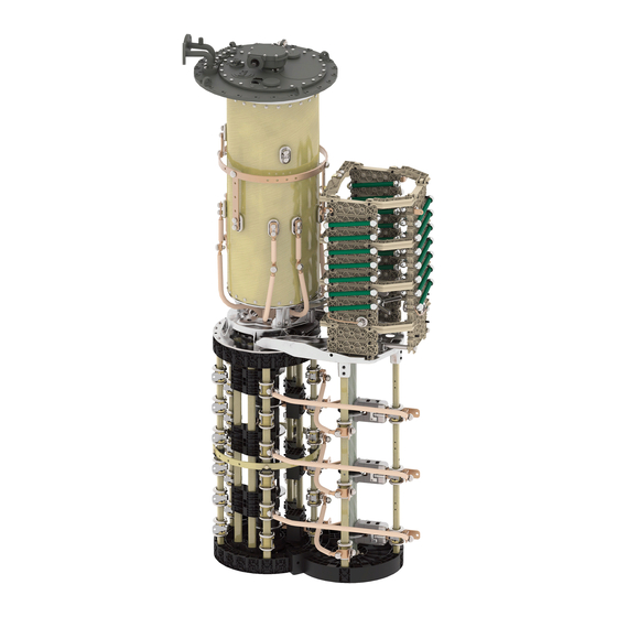
3 Product description A motor-drive unit, which receives a control impulse (e.g. from a voltage reg- ulator), changes the on-load tap-changer's operating position, which adapts the transmission ratio of the transformer to the respective operating require- ments. Figure 3: System overview of on-load tap-changer Transformer Transformer tank Upper gear unit Motor-drive unit... - Page 27 3 Product description For the number of maximum operating positions of the on-load tap-changer, refer to the Technical data. Figure 4: VACUTAP® VRC/VRE On-load tap-changer head Tap selector Oil compartment Change-over selector Maschinenfabrik Reinhausen GmbH 2017 5293014/00 EN VACUTAP® VR I HD-Ex...
- Page 28 3 Product description Figure 5: VACUTAP® VRD/VRF On-load tap-changer head Tap selector Oil compartment Change-over selector VACUTAP® VR I HD-Ex 5293014/00 EN Maschinenfabrik Reinhausen GmbH 2017...
- Page 29 3 Product description Figure 6: VACUTAP® VRG On-load tap-changer head Tap selector Oil compartment Change-over selector 3.2.2.1 Pipe connections The on-load tap-changer head features 4 pipe connections for different pur- poses. Maschinenfabrik Reinhausen GmbH 2017 5293014/00 EN VACUTAP® VR I HD-Ex...
- Page 30 3 Product description Depending on the order, some or all of these pipe connections are fitted with pipe bends ex factory. All pipe bends without terminal box for the tap-change supervisory control can be freely swiveled once the pressure ring is loos- ened.
-
Page 31: Name Plate
3 Product description between the transformer tank and oil compartment of the on-load tap-chang- er, which is necessary for drying, oil filling and transportation of the trans- former. 3.2.3 Name plate The name plate is on the on-load tap-changer head cover. Figure 8: Position of name plate Drive shaft 3.3.1... - Page 32 3 Product description The explosion-proof drive shaft consists of a square tube with insulator and is coupled by two coupling brackets and one coupling bolt at both ends to the drive or driven shaft end of the device to be connected. Figure 9: Explosion-proof drive shaft with insulator VACUTAP®...
-
Page 33: Design/Model
3 Product description 3.3.2 Design/Model The design of the explosion-proof drive shaft is described in this section. Figure 10: Components of the explosion-proof drive shaft Bevel gear Hose clip Screws Telescopic protective tube Coupling bracket Insulator Double coupling bracket Square tube Adapter ring Protective cover Hose clip... - Page 34 3 Product description Configuration V 1 min Intermediate bearing VACUTAP® VR I HD-Ex 5293014/00 EN Maschinenfabrik Reinhausen GmbH 2017...
-
Page 35: Identification Plate
3 Product description Distance between middle of 706 mm When the maximum hand crank and middle of bevel value of 2472 mm is gear exceeded, it is neces- sary to use an inter- mediate bearing. V 1 ≤ 2472 mm (with- out intermediate bear- ing) V 1 >... -
Page 36: Setup/Versions
3 Product description The protective relay is part of an on-load tap-changer filled with insulating liquid and its properties conform to the applicable valid version of IEC publi- cation 60214-1. Diverter switch operations at rated switching capacity or at permissible over- load will not cause the protective relay to trip. -
Page 37: Name Plate
3 Product description View from above Figure 14: RS 2001-Ex Gasket Potential tie-in Terminal box cover OPERATION (reset) test but- Slotted head screw for poten- OFF (test tripping) test button tial tie-in Protective conductor connec- Protective cover with picto- tion gram for terminal assignment Dummy plug Connection terminal... -
Page 38: Packaging, Transport And Storage
4 Packaging, transport and storage Packaging, transport and storage Packaging The products are sometimes supplied with a sealed packaging and some- times also dried depending on what is required. A sealed packaging surrounds the packaged goods on all sides with plastic foil. -
Page 39: Transportation, Receipt And Handling Of Shipments
4 Packaging, transport and storage Transportation, receipt and handling of shipments Danger of death and damage to property! WARNING Danger of death and damage to property due to tipping or falling load. ► Transport crate when closed only. ► Do not remove the mounting material used in the crate during transport. ►... -
Page 40: Storage Of Shipments
4 Packaging, transport and storage changer/de-energized tap-changer or contact Maschinenfabrik Reinhau- sen GmbH to agree on how to proceed with drying. If this is not done, the packaged goods may be damaged. ▪ Name the damaged parts. Hidden damage When damages are not determined until unpacking after receipt of the ship- ment (hidden damage), proceed as follows: ▪... -
Page 41: Unpacking Shipments And Checking For Transportation Damages
4 Packaging, transport and storage If the product is installed more than 6 months after delivery, suitable meas- ures must be taken without delay. The following measures can be used: ▪ Correctly regenerate the drying agent and restore the sealed packaging. ▪... -
Page 42: Mounting
5 Mounting Mounting Risk of crushing from moving parts! WARNING When the on-load tap-changer undertakes a tap-change operation, compo- nents move on the selector, change-over selector, and potential connection unit, some of which are freely accessible. Reaching into the selector, change-over selector or potential connection unit during a tap-change oper- ation may result in serious injuries. -
Page 43: Fitting Mounting Flange On Transformer Cover
5 Mounting 5.1.1 Fitting mounting flange on transformer cover A mounting flange is required for fitting the on-load tap-changer head on the transformer cover. This can be supplied as an option or can be produced by the customer. Mounting flanges made by the customer must comply with the installation drawings in the appendix. -
Page 44: Installing The Standard Version On-Load Tap-Changer In The Transformer
5 Mounting Fit stud bolts on mounting flange. Figure 17: Tracing template, stud bolts Installing the standard version on-load tap-changer in the transformer Perform the work stated below in order to install the on-load tap-changer in the transformer (standard version). 5.2.1 Fastening on-load tap-changer to transformer cover This chapter describes how to fasten the on-load tap-changer to the trans-... - Page 45 5 Mounting CAUTION! Place the oil compartment on a level surface and secure it against tipping. An unstably positioned oil compartment may tip over, resulting in serious injuries and damage. Clean sealing surfaces on mounting flange and on-load tap-changer head, place oil-resistant gasket on mounting flange. Figure 18: Sealing surfaces, seal Maschinenfabrik Reinhausen GmbH 2017 5293014/00 EN...
- Page 46 5 Mounting Lift the oil compartment by hooking up the on-load tap-changer head and carefully lower the oil compartment into the cover opening of the transformer. Figure 19: Oil compartment Check that the on-load tap-changer head is mounted in the position specified by the design.
- Page 47 5 Mounting Screw on-load tap-changer head to mounting flange. Figure 20: On-load tap-changer head with mounting flange Remove the blocking device from the coupling of the oil compartment base. Figure 21: VACUTAP® VRC/VRE, blocking strip Maschinenfabrik Reinhausen GmbH 2017 5293014/00 EN VACUTAP®...
- Page 48 5 Mounting Figure 22: VACUTAP® VRD/VRF, blocking plate and shackle Figure 23: VACUTAP® VRG, blocking plate and shackle VACUTAP® VR I HD-Ex 5293014/00 EN Maschinenfabrik Reinhausen GmbH 2017...
- Page 49 5 Mounting 5.2.1.2 Securing tap selector on oil compartment of the on-load tap-changer VRC/VRE WARNING! Place the selector on a level surface and secure it CAUTION! . An unstably positioned selector may tip, against tipping resulting in injuries and property damage. Remove plastic bag with fastening materials from the selector and keep them ready.
- Page 50 5 Mounting NOTICE! Carefully lift selector below the oil compartment, ensuring that the tap-selector connecting leads are free when lifting the selector on the oil compartment and do not touch the compartment. Failure to com- ply with this instruction may result in the tap-selector connecting leads being damaged.
- Page 51 5 Mounting Remove plastic bag with fastening materials from the selector and keep them ready. Figure 27: Plastic bag with fastening materials Remove the blocking strip from the selector coupling. Once the blocking strip is removed, the selector coupling must no longer be turned. Figure 28: Blocking strip Place the selector on the lifting device.
- Page 52 5 Mounting Remove the ring nuts from the selector. Figure 29: Ring nut NOTICE! Carefully lift selector below the oil compartment, ensuring that the tap-selector connecting leads are free when lifting the selector on the oil compartment and do not touch the compartment. Failure to com- ply with this instruction may result in the tap-selector connecting leads being damaged.
- Page 53 5 Mounting 5.2.1.4 Securing tap selector on oil compartment of the on-load tap-changer WARNING! Place the selector on a level surface and secure it CAUTION! . An unstably positioned selector may tip, against tipping resulting in injuries and property damage. Remove plastic bag with fastening materials from the selector and keep them ready.
- Page 54 5 Mounting Remove the ring nuts from the selector. Figure 33: Ring nut NOTICE! Carefully lift selector below the oil compartment, ensuring that the tap-selector connecting leads are free when lifting the selector on the oil compartment and do not touch the compartment. Failure to com- ply with this instruction may result in the tap-selector connecting leads being damaged.
- Page 55 5 Mounting 5.2.1.5 Connecting tap-selector connecting leads Proceed as follows to connect the tap-selector connecting leads: NOTICE! Carefully screw tap-selector connecting leads to connecting piece or ring segment. Comply with specified tightening torque and se- cure screw connection. Failure to do so may result in damage to the on- load tap-changer and transformer.
-
Page 56: Connecting The Tap Winding And On-Load Tap-Changer Take-Off Lead
5 Mounting 5.2.2 Connecting the tap winding and on-load tap-changer take-off lead NOTICE Damage to the on-load tap-changer! Connecting leads which place mechanical strain on the on-load tap-changer will damage the on-load tap-changer! ► Establish connections carefully. ► Do not twist connection contacts. ►... - Page 57 5 Mounting Figure 38: Screening caps 5.2.2.2 Selector connection contacts for multiple coarse change-over selector In the case of multiple coarse change-over selectors, take care when routing the cables for connecting to the selector connection contacts and the multi- ple coarse change-over selector connection contacts. These cables should be as far away as possible from neighboring connection contacts.
- Page 58 5 Mounting In this regard, please also pay attention to the dimensional drawing on which the order is based. Figure 39: Paper insulation Connection from MR already Connections to be insulated has 3 mm of paper insulation 5.2.2.3 Change-over selector connection contacts for reversing change-over...
- Page 59 5 Mounting NOTICE Damage to the on-load tap-changer! Tap-winding connecting leads situated too closely to the change-over selec- tor's moving parts block the change-over selector and therefore result in on- load tap-changer damage! ► Tap-winding connecting leads in the area of the change-over selector have to be routed such that they are at a sufficient distance from the change-over selector's moving parts.
- Page 60 5 Mounting 5.2.2.4 Change-over selector connection contacts for coarse tap selector connection VRC/VRE With coarse tap selector connection, the (+) and (-) change-over selector connection contacts are secured to the respective laminated paper bars of the coarse change-over selector. Their external appearance is identical to the fine tap selector contacts (through-hole for M10 screws, always in verti- cal position).
- Page 61 5 Mounting Figure 43: Change-over selector connection contacts for coarse tap selector connec- tion (top view) 5.2.2.5 Selector connection contacts VRD/VRF The selector connection contacts have a through-hole for M12 screws. The screening caps are supplied separately. Figure 44: Selector connection contacts Maschinenfabrik Reinhausen GmbH 2017 5293014/00 EN VACUTAP®...
- Page 62 5 Mounting 5.2.2.6 Change-over selector connection contacts for reversing change-over selector connection VRD/VRF The (+) and (-) change-over selector connection contacts are designed like fine tap selector connection contacts for reversing change-over selector con- nections. The change-over selector connection contacts (0) are produced as terminal lugs of the crimped connecting lead (=0/K) with a through-hole for M12 screws.
- Page 63 5 Mounting 5.2.2.9 Fine-tap-selector and change-over-selector connection contacts VRG The selector connection contacts are indicated on the selector bars. The connection is made at the thread stud of the selector connection contact via cable shoes and locknuts. Every connection point must be covered by a screening cap. The screening caps are designed for lateral connection with a straight cable shoe or for front connection with an angled cable shoe.
-
Page 64: Carrying Out Transformer Ratio Test Before Drying
5 Mounting 5.2.2.10 Parallel bridges for VRG I 1601/1801 Bridges for connecting the connection contacts of the fine tap selector and change-over selector in parallel in accordance with drawing 786920 will be supplied. 5.2.2.11 Connecting on-load tap-changer take-off lead There are through-holes 13 mm in diameter at several points in the take-off ring of the oil compartment for connecting the on-load tap-changer take-off lead. -
Page 65: Measuring Dc Resistance On Transformer
5 Mounting NOTICE Damage to property! Damage to on-load tap-changer due to transformer ratio test being incor- rectly performed! ► Do not perform more than 250 tap-change operations on the on-load tap-changer. If more than 250 tap-change operations are performed, completely fill oil compartment with insulating oil and lubricate sliding surfaces of contacts on selector and selector gear with insulating oil. -
Page 66: Drying On-Load Tap-Changer In Autoclave
► Within 10 hours of drying, seal off oil compartment with on-load tap- changer head cover. Dry on-load tap-changer using the following instructions to ensure the dielec- tric values assured by MR on the on-load tap-changer. If drying in an autoclave, the following methods are possible: ▪... - Page 67 5 Mounting Vacuum-drying in the autoclave Heat up the on-load tap-changer in air at atmospheric pressure with a temperature increase of about 10 °C/h to a final temperature of maxi- mum 110 °C. Pre-dry the on-load tap-changer in circulating air at a max. temperature of 110 °C for a period of 20 hours.
-
Page 68: Drying On-Load Tap-Changer In Transformer Tank
Dry on-load tap-changer using the following instructions to ensure the dielec- tric values assured by MR on the on-load tap-changer. If you want to dry the on-load tap-changer in the transformer tank, first com- plete transformer assembly and then undertake drying. - Page 69 5 Mounting Seal off unused pipe connections with a suitable blank cover. Figure 51: Connecting lead Vacuum-drying in the transformer tank Heat up the on-load tap-changer in air at atmospheric pressure with a temperature increase of about 10 °C/h to a final temperature of maxi- mum 110 °C.
- Page 70 5 Mounting NOTICE Damage to the on-load tap-changer! Damage to the on-load tap-changer and oil suction pipe due to incorrect or- der of installation. ► Strictly adhere to the order of installation. Make sure to always install the diverter switch insert before inserting the oil suction pipe into the oil compartment.
- Page 71 5 Mounting NOTICE Damage to the on-load tap-changer and transformer! Small parts in the oil compartment may block the diverter switch insert, thereby damaging the on-load tap-changer and transformer! ► Take care to avoid parts falling into the oil compartment. ►...
- Page 72 5 Mounting 5.2.6.2.1.3 Removing tap position indicator (version without multiple coarse change-over selector) ► Pull the spring clip off the shaft end and remove the tap position indica- tor disc. Figure 55: Tap position indicator disk 5.2.6.2.1.4 Removing tap position indicator from multiple coarse change-over selector with more than 35 operating positions Ensure that the red marks on the panel, tap position indicator disk and cover disk produce a continuous red line.
- Page 73 5 Mounting Lever cover disk off underlying disk with flat screwdriver and pull out po- sition-indication disk from between panel and bracket. Figure 57: Cover disk and position-indication disk Remove hexagon screws and associated lock tab. Figure 58: Lock tab Pull panel and bracket up and off indicator drive shaft.
- Page 74 5 Mounting 5.2.6.2.1.5 Removing the tap-change supervisory device Damage to the on-load tap-changer and transformer! NOTICE Removing the tap-change monitoring unit without due care may damage it, thereby resulting in damage to the on-load tap-changer and transformer! ► Disconnect tap-change monitoring unit with care in order not to damage or rip out the connecting leads.
- Page 75 5 Mounting Remove tap-change supervisory device with mounting plate and drive shaft. Figure 62: Tap-change supervisory device with mounting plate and drive shaft Swivel the lead of the tap-change supervisory device out of the on-load tap-changer head in direction indicated by the arrow until the cable will not be damaged when the on-load tap-changer insert is pulled out.
- Page 76 5 Mounting 5.2.6.2.1.6 Removing the oil suction pipe Remove cable ties from the oil suction pipe. Figure 63: Cable tie Pull oil suction pipe out of on-load tap-changer head. Figure 64: Oil suction pipe 5.2.6.2.1.7 Lifting out diverter switch insert By turning the coupling tube on the upper screening ring, align it in such a manner that the triangular marks on the on-load tap-changer head and those on the coupling tube match up.
- Page 77 5 Mounting Insert the lifting gear in the eyebolts of the coupling tube and position vertically above the diverter switch insert. Lift the diverter switch insert slowly and vertically out of oil compartment. Figure 66: Diverter switch insert CAUTION! Place the diverter switch insert on a level surface and se- cure it against tipping.
- Page 78 5 Mounting 5.2.6.2.3 Inserting diverter switch insert Proceed as follows to insert the diverter switch insert. 5.2.6.2.3.1 Inserting diverter switch insert Check that all six insulating shims are present in the energy accumula- tor carrier. Figure 68: Insulating shim VACUTAP® VR I HD-Ex 5293014/00 EN Maschinenfabrik Reinhausen GmbH 2017...
- Page 79 5 Mounting To fit the diverter switch insert, ensure that the tap selector coupling is in the adjustment position. Figure 69: Adjustment markings in oil compartment base VACUTAP® VRC/VRE Figure 70: Adjustment markings in oil compartment base VACUTAP® VRD/VRF Maschinenfabrik Reinhausen GmbH 2017 5293014/00 EN VACUTAP®...
- Page 80 5 Mounting Figure 71: Adjustment markings in oil compartment base VACUTAP® VRG Ensure that the diverter switch insert's energy accumulator is inter- locked (the energy accumulator's eccentric disk is at its highest point). Attach lifting gear to diverter switch insert and position diverter switch in- sert over oil compartment.
- Page 81 5 Mounting Slowly lower diverter switch insert until it meets the oil compartment base. Figure 72: Markings Carefully press until energy accumulator carrier is in position. The shape of the tap selector coupling ensures that coupling is only possible in the correct position.
- Page 82 5 Mounting Check the distance between the upper edge of the diverter switch insert coupling tube and the on-load tap-changer head flange. The distance is 10 ± 2 mm (cover mounting and bell-type tank mounting). Figure 73: Distance between the upper edge of the coupling tube and the on-load tap-changer head flange 5.2.6.2.3.2 Inserting oil suction pipe...
- Page 83 5 Mounting Fasten oil suction pipe on retaining bracket with cable tie. Figure 75: Fastening the oil suction pipe 5.2.6.2.3.3 Inserting the tap-change supervisory device Insert tap-change supervisory device with mounting plate and drive shaft. Figure 76: Mounting plate with drive shaft Maschinenfabrik Reinhausen GmbH 2017 5293014/00 EN VACUTAP®...
- Page 84 5 Mounting Check that drive shaft feather key is seated correctly in the groove. Figure 77: Feather key and groove Secure mounting plate (3 or 4 nuts and locking elements depending on model). Figure 78: Mounting plate Connect plug connector outside its bracket. Figure 79: Plug connector VACUTAP®...
- Page 85 5 Mounting Insert plug connector into the bracket. Figure 80: Plug connector in bracket 5.2.6.2.3.4 Inserting the tap position indicator without multiple coarse change- over selector Due to the coupling pin, the tap position indicator disc can only be installed when in the correct position.
- Page 86 5 Mounting 5.2.6.2.3.5 Inserting tap position indicator with multiple coarse change-over selector with more than 35 operating positions Place panel with bracket on indicator drive shaft and fasten with hexa- gon screws and associated lock tab. Figure 82: Fitting panel Insert position-indication disk horizontally between panel and bracket and fit cover disk.
- Page 87 5 Mounting Secure cover disk with countersunk head screw. The countersunk head screw must be suitable for center-punching. Figure 84: Fastening cover disk Secure countersunk head screw by center-punching. 5.2.6.2.3.6 Securing on-load tap-changer head cover NOTICE! Place on-load tap-changer head cover on on-load tap-chang- er head and take care not to damage the o-ring inserted in the on-load tap-changer head cover.
- Page 88 5 Mounting Screw on-load tap-changer head cover using screws and washers. Figure 86: On-load tap-changer head cover 5.2.6.2.4 Drying the on-load tap-changer Connect pipe connections R and Q of on-load tap-changer head to the kerosene vapor lead using one shared lead. Seal off unused pipe connections with a suitable blank cover.
-
Page 89: Carrying Out Transformer Ratio Test After Drying
5 Mounting If you wish to perform another transformer ratio test after drying, proceed as described in the section "Performing transformer ratio test following drying". 5.2.7 Carrying out transformer ratio test after drying To perform the transformer ratio test, proceed as follows: NOTICE Damage to property! Damage to on-load tap-changer due to transformer ratio test being incor-... -
Page 90: Installing On-Load Tap-Changer In Transformer (Bell-Type Tank Version)
5 Mounting NOTICE! After operating the diverter switch, continue to crank 2.5 revo- lutions in the same direction on the drive shaft of the upper gear unit in order to correctly end the tap-change operation. An incomplete tap- change operation may damage the on-load tap-changer! Carry out the transformer ratio test. - Page 91 5 Mounting Remove the blocking strip from the tap selector coupling. Once the blocking strip is removed, the tap selector coupling must no longer be turned. Figure 89: Blocking strip CAUTION! Place the oil compartment on a level surface and secure it against tipping.
- Page 92 5 Mounting Align the position of both coupling parts and attachment points on the oil compartment and the tap selector with one another. The correct position of the two coupling parts is shown in the adjustment plans in the appen- dix.
- Page 93 5 Mounting Remove the ring nuts from the tap selector. Figure 93: Ring nut Remove the blocking strip from the tap selector coupling. Once the blocking strip is removed, the tap selector coupling must no longer be turned. Figure 94: Blocking strip CAUTION! Place the oil compartment on a level surface and secure it against tipping.
- Page 94 5 Mounting Lift the oil compartment by hooking up the on-load tap-changer head and remove the blocking device on the coupling of the oil compartment base. Figure 95: Blocking plate and shackle Carefully raise oil compartment above tap selector. Align the position of both coupling parts and attachment points on the oil compartment and the tap selector with one another.
- Page 95 5 Mounting Screw tap selector onto oil compartment. Figure 96: Tap selector with oil compartment 5.3.1.3 Securing tap selector on oil compartment of the on-load tap-changer CAUTION! Place the tap selector on a level surface and secure it against tipping. An unstably positioned tap selector may tip, resulting in serious injuries and damage.
- Page 96 5 Mounting Remove the ring nuts from the tap selector. Figure 98: Ring nut Remove the blocking strip from the tap selector coupling. Once the blocking strip is removed, the tap selector coupling must no longer be turned. Figure 99: Blocking strip CAUTION! Place the oil compartment on a level surface and secure it against tipping.
- Page 97 5 Mounting Lift the oil compartment by hooking up the on-load tap-changer head and remove the blocking device on the coupling of the oil compartment base. Figure 100: Blocking plate and shackle Carefully raise oil compartment above tap selector. Align the position of both coupling parts and attachment points on the oil compartment and the tap selector with one another.
- Page 98 5 Mounting 5.3.1.4 Connecting tap-selector connecting leads Proceed as follows to connect the tap-selector connecting leads: NOTICE! Carefully screw tap-selector connecting leads to connecting piece or ring segment. Comply with specified tightening torque and se- cure screw connection. Failure to do so may result in damage to the on- load tap-changer and transformer.
- Page 99 5 Mounting are connected, tension may occur which will damage the on-load tap- changer and transformer. There is also a risk of malfunctions from se- lector contacts moving to the closing position incorrectly. Figure 104: On-load tap-changer with spacers on supporting structure Remove red supports on selector base (if present).
-
Page 100: Connecting The Tap Winding And On-Load Tap-Changer Take-Off Lead
5 Mounting Temporarily fasten on-load tap-changer to supporting structure. The supporting flange has through holes for this purpose. Figure 105: Fastening the on-load tap-changer 5.3.2 Connecting the tap winding and on-load tap-changer take-off lead Damage to the on-load tap-changer! NOTICE Connecting leads which place mechanical strain on the on-load tap-changer will damage the on-load tap-changer! ►... - Page 101 5 Mounting The through-holes of the connection contacts are either horizontal or verti- cal, depending on the on-load tap-changer version. Figure 106: Selector connection contacts Figure 107: Screening caps 5.3.2.2 Selector connection contacts for multiple coarse change-over selector In the case of multiple coarse change-over selectors, take care when routing the cables for connecting to the selector connection contacts and the multi- ple coarse change-over selector connection contacts.
- Page 102 In this regard, please also pay attention to the dimensional drawing on which the order is based. Figure 108: Paper insulation Connection from MR already Connections to be insulated has 3 mm of paper insulation 5.3.2.3...
- Page 103 5 Mounting Connection contact K is designed as an extended fine tap selector connec- tion contact (also with through-hole for M10 screws). Figure 109: Change-over selector connection contacts for reversing change-over se- lector connection NOTICE Damage to the on-load tap-changer! Tap-winding connecting leads situated too closely to the change-over selec- tor's moving parts block the change-over selector and therefore result in on- load tap-changer damage!
- Page 104 5 Mounting 5.3.2.4 Change-over selector connection contacts for coarse tap selector connection VRC/VRE With coarse tap selector connection, the (+) and (-) change-over selector connection contacts are secured to the respective laminated paper bars of the coarse change-over selector. Their external appearance is identical to the fine tap selector contacts (through-hole for M10 screws, always in verti- cal position).
- Page 105 5 Mounting Figure 112: Change-over selector connection contacts for coarse tap selector con- nection (top view) 5.3.2.5 Selector connection contacts VRD/VRF The selector connection contacts have a through-hole for M12 screws. The screening caps are supplied separately. Figure 113: Selector connection contacts Maschinenfabrik Reinhausen GmbH 2017 5293014/00 EN VACUTAP®...
- Page 106 5 Mounting 5.3.2.6 Change-over selector connection contacts for reversing change-over selector connection VRD/VRF The (+) and (-) change-over selector connection contacts are designed like fine tap selector connection contacts for reversing change-over selector con- nections. The change-over selector connection contacts (0) are produced as terminal lugs of the crimped connecting lead (=0/K) with a through-hole for M12 screws.
- Page 107 5 Mounting 5.3.2.9 Fine-tap-selector and change-over-selector connection contacts VRG The selector connection contacts are indicated on the selector bars. The connection is made at the thread stud of the selector connection contact via cable shoes and locknuts. Every connection point must be covered by a screening cap. The screening caps are designed for lateral connection with a straight cable shoe or for front connection with an angled cable shoe.
-
Page 108: Carrying Out Transformer Ratio Test Before Drying
5 Mounting 5.3.2.10 Parallel bridges for VRG I 1601/1801 Bridges for connecting the connection contacts of the fine tap selector and change-over selector in parallel in accordance with drawing 786920 will be supplied. 5.3.2.11 Connecting on-load tap-changer take-off lead There are through-holes 13 mm in diameter at several points in the take-off ring of the oil compartment for connecting the on-load tap-changer take-off lead. -
Page 109: Measuring Dc Resistance On Transformer
5 Mounting NOTICE Damage to property! Damage to on-load tap-changer due to transformer ratio test being incor- rectly performed! ► Do not perform more than 250 tap-change operations on the on-load tap-changer. If more than 250 tap-change operations are performed, completely fill oil compartment with insulating oil and lubricate sliding surfaces of contacts on selector and selector gear with insulating oil. -
Page 110: Drying On-Load Tap-Changer In Autoclave
► Within 10 hours of drying, seal off oil compartment with on-load tap- changer head cover. Dry on-load tap-changer using the following instructions to ensure the dielec- tric values assured by MR on the on-load tap-changer. If drying in an autoclave, the following methods are possible: ▪... - Page 111 5 Mounting Vacuum-drying in the autoclave Heat up the on-load tap-changer in air at atmospheric pressure with a temperature increase of about 10 °C/h to a final temperature of maxi- mum 110 °C. Pre-dry the on-load tap-changer in circulating air at a max. temperature of 110 °C for a period of 20 hours.
-
Page 112: Lifting Top Part Of On-Load Tap-Changer Head Off Supporting Flange (Bottom Part)
5 Mounting Increase the kerosene vapor temperature by approx. 10 °C/hour to the desired final temperature of max. 125 °C at the on-load tap-changer. Vacuum dry on-load tap-changer at between 105 °C and maximum 125 °C for at least 50 hours. Residual pressure of no more than 10 bar. - Page 113 5 Mounting Remove temporary fastening and spacers and slowly lower on-load tap- changer. Figure 120: Removing fastening Loosen screws with locking elements on on-load tap-changer head cov- Figure 121: On-load tap-changer head cover NOTICE! Remove the on-load tap-changer head cover. Make sure that sealing surfaces on the on-load tap-changer head cover and on-load tap-changer head are in sound condition when removing and during all Maschinenfabrik Reinhausen GmbH 2017...
- Page 114 5 Mounting other work and that the o-ring is also undamaged. Damaged sealing surfaces lead to oil escaping and therefore to on-load tap-changer and transformer damage. Figure 122: On-load tap-changer head cover 5.3.6.2 Removing tap position indicator (version without multiple coarse change-over selector) ►...
- Page 115 5 Mounting Remove countersunk head screw. Figure 124: Countersunk head screw Lever cover disk off underlying disk with flat screwdriver and pull out po- sition-indication disk from between panel and bracket. Figure 125: Cover disk and position-indication disk Remove hexagon screws and associated lock tab. Figure 126: Lock tab Maschinenfabrik Reinhausen GmbH 2017 5293014/00 EN...
- Page 116 5 Mounting Pull panel and bracket up and off indicator drive shaft. Figure 127: Panel 5.3.6.4 Removing the tap-change supervisory device NOTICE Damage to the on-load tap-changer and transformer! Removing the tap-change monitoring unit without due care may damage it, thereby resulting in damage to the on-load tap-changer and transformer! ►...
- Page 117 5 Mounting Remove nuts and locking elements (3 or 4 depending on model) on the mounting plate. Figure 129: Mounting plate Remove mounting plate with tap-change supervisory device and drive shaft. Figure 130: Tap-change supervisory device with mounting plate and drive shaft Maschinenfabrik Reinhausen GmbH 2017 5293014/00 EN VACUTAP®...
- Page 118 5 Mounting Lift the lead of the tap-change supervisory device off the spacer bolt. Figure 131: Spacer bolt and lead of the tap-change supervisory device Swivel lead of the tap-change supervisory device out of the on-load tap- changer head. Figure 132: Lead of tap-change supervisory device VACUTAP®...
- Page 119 5 Mounting Remove spacer bolt with locking element. Spacer bolt 5.3.6.5 Removing the oil suction pipe Remove cable ties from the oil suction pipe. Figure 133: Cable tie Pull oil suction pipe out of on-load tap-changer head. Figure 134: Oil suction pipe Maschinenfabrik Reinhausen GmbH 2017 5293014/00 EN VACUTAP®...
- Page 120 5 Mounting Remove mounting bracket Figure 135: Mounting bracket 5.3.6.6 Lift the top part of the on-load tap-changer head off the bottom part Remove nuts and locking elements between top part and bottom part of on-load tap-changer head. Figure 136: Top part of on-load tap-changer head with nuts VACUTAP®...
-
Page 121: Fit The Bell-Type Tank And Connect The On-Load Tap-Changer To The Top Part Of The On-Load Tap-Changer Head
5 Mounting Lift top part of on-load tap-changer head off bottom part. Figure 137: Top part of on-load tap-changer head 5.3.7 Fit the bell-type tank and connect the on-load tap-changer to the top part of the on-load tap-changer head The following chapters explain how to connect the on-load tap-changer to the upper part of the on-load tap-changer head once the bell-type tank has been fitted. - Page 122 5 Mounting 5.3.7.1 Mounting the bell-type tank Clean sealing surface of supporting flange, place o-ring on supporting flange. Figure 138: Supporting flange with o-ring Lift the bell-type tank over the active part of the transformer. Figure 139: Bell-type tank VACUTAP® VR I HD-Ex 5293014/00 EN Maschinenfabrik Reinhausen GmbH 2017...
- Page 123 5 Mounting 5.3.7.2 Positioning top part of on-load tap-changer head on bell-type tank Clean sealing surfaces on mounting flange and top part of on-load tap- changer head, place oil-resistant gasket on mounting flange. Figure 140: Mounting flange with gasket Gasket Mounting flange Maschinenfabrik Reinhausen GmbH 2017 5293014/00 EN...
- Page 124 5 Mounting Position top part of on-load tap-changer head on mounting flange so that the markings on the top part and bottom part of the on-load tap- changer head match up. Pay attention to fitted bolt in bottom part. Figure 141: Markings and fitted bolt VACUTAP®...
- Page 125 5 Mounting 5.3.7.3 Connecting on-load tap-changer to top part of on-load tap-changer head Carefully insert lifting device into the oil compartment with claws turned Figure 142: Lifting device NOTICE! Swing claws of lifting device outwards, use lifting device to lift oil compartment.
- Page 126 5 Mounting When fitting the top part and bottom part of the on-load tap-changer head together, leave the pins for the mounting plate of the tap-change superviso- ry device as well as the pins for the mounting bracket of the oil suction pipe (if present) free.
- Page 127 5 Mounting Screw on-load tap-changer head to mounting flange. Figure 146: Screwing on-load tap-changer head to mounting flange 5.3.7.4 Inserting oil suction pipe NOTICE Damage to the on-load tap-changer! Damage to the on-load tap-changer and oil suction pipe due to incorrect or- der of installation.
- Page 128 5 Mounting Insert oil suction pipe into on-load tap-changer head. Figure 148: Inserting oil suction pipe Fasten oil suction pipe on retaining bracket with cable tie. Figure 149: Fastening the oil suction pipe VACUTAP® VR I HD-Ex 5293014/00 EN Maschinenfabrik Reinhausen GmbH 2017...
- Page 129 5 Mounting 5.3.7.5 Inserting the tap-change supervisory device Insert mounting plate with tap-change supervisory device and drive shaft. Figure 150: Mounting plate with tap-change supervisory device and drive shaft Check that drive shaft feather key is seated correctly in the groove. Figure 151: Feather key and groove Maschinenfabrik Reinhausen GmbH 2017 5293014/00 EN...
- Page 130 5 Mounting Secure mounting plate (3 or 4 nuts and locking elements depending on model). Figure 152: Mounting plate Spacer bolt for fastening the lead of the tap-change supervisory device. Figure 153: Spacer bolt VACUTAP® VR I HD-Ex 5293014/00 EN Maschinenfabrik Reinhausen GmbH 2017...
- Page 131 5 Mounting Fasten lead of tap-change supervisory device to spacer bolt. Figure 154: Stud bolt with Teflon strip and nut Connect plug connector outside its bracket. Figure 155: Plug connector Insert plug connector into the bracket. Figure 156: Plug connector in bracket Maschinenfabrik Reinhausen GmbH 2017 5293014/00 EN VACUTAP®...
- Page 132 5 Mounting 5.3.7.6 Inserting the tap position indicator without multiple coarse change- over selector Due to the coupling pin, the tap position indicator disc can only be installed when in the correct position. ► Place tap position indicator disk on indicator drive shaft, slide spring clip on to shaft end.
- Page 133 5 Mounting Insert position-indication disk horizontally between panel and bracket and fit cover disk. Align tap position indicator disc and cover disk to pro- duce a continuous red line. Figure 159: Inserting position-indication disk Secure cover disk with countersunk head screw. The countersunk head screw must be suitable for center-punching.
-
Page 134: Drying On-Load Tap-Changer In Transformer Tank
Dry on-load tap-changer using the following instructions to ensure the dielec- tric values assured by MR on the on-load tap-changer. If you want to dry the on-load tap-changer in the transformer tank, first com- plete transformer assembly and then undertake drying. - Page 135 5 Mounting If drying in the transformer tank, the following methods are possible: ▪ Vacuum-drying ▪ Vapor-phase drying 5.3.8.1 Vacuum-drying in the transformer tank To vacuum dry the on-load tap-changer in the transformer tank, proceed as follows. The on-load tap-changer head cover remains closed during the entire drying process.
- Page 136 5 Mounting 5.3.8.2 Vapor-phase drying in the transformer tank If you have not opened the kerosene drain plug in advance (e.g. after the transformer ratio test), you have to open the kerosene drain plug before dry- ing the kerosene in the transformer tank so that the kerosene condensate can drain from the oil compartment.
- Page 137 5 Mounting 5.3.8.2.1.2 Removing on-load tap-changer head cover Danger of explosion! WARNING Danger of death from explosive gases under the on-load tap-changer head cover! ► Ensure that there are no open flames, hot surfaces or sparks (for exam- ple caused by static charging) in the immediate surroundings and that none arise.
- Page 138 5 Mounting other work and that the o-ring is also undamaged. Damaged sealing surfaces lead to oil escaping and therefore to on-load tap-changer and transformer damage. Figure 166: On-load tap-changer head cover 5.3.8.2.1.3 Removing tap position indicator (version without multiple coarse change-over selector) ►...
- Page 139 5 Mounting Remove countersunk head screw. Figure 168: Countersunk head screw Lever cover disk off underlying disk with flat screwdriver and pull out po- sition-indication disk from between panel and bracket. Figure 169: Cover disk and position-indication disk Remove hexagon screws and associated lock tab. Figure 170: Lock tab Maschinenfabrik Reinhausen GmbH 2017 5293014/00 EN...
- Page 140 5 Mounting Pull panel and bracket up and off indicator drive shaft. Figure 171: Panel 5.3.8.2.1.5 Removing the tap-change supervisory device NOTICE Damage to the on-load tap-changer and transformer! Removing the tap-change monitoring unit without due care may damage it, thereby resulting in damage to the on-load tap-changer and transformer! ►...
- Page 141 5 Mounting Remove nuts and locking elements (3 or 4 depending on model) on the mounting plate. Figure 173: Mounting plate Remove tap-change supervisory device with mounting plate and drive shaft. Figure 174: Tap-change supervisory device with mounting plate and drive shaft Maschinenfabrik Reinhausen GmbH 2017 5293014/00 EN VACUTAP®...
- Page 142 5 Mounting Swivel the lead of the tap-change supervisory device out of the on-load tap-changer head in direction indicated by the arrow until the cable will not be damaged when the on-load tap-changer insert is pulled out. Swiveling out the lead of the tap-change supervisory device 5.3.8.2.1.6 Removing the oil suction pipe Remove cable ties from the oil suction pipe.
- Page 143 5 Mounting 5.3.8.2.1.7 Lifting out diverter switch insert By turning the coupling tube on the upper screening ring, align it in such a manner that the triangular marks on the on-load tap-changer head and those on the coupling tube match up. Figure 177: Aligning the coupling tube Insert the lifting gear in the eyebolts of the coupling tube and position vertically above the diverter switch insert.
- Page 144 5 Mounting 5.3.8.2.2 Opening kerosene drain plug NOTICE! ► Unscrew kerosene drain plug with extended socket wrench counter-clockwise until it starts to get hard to turn.Never unscrew the kerosene drain plug all the way. Figure 179: Kerosene drain plug 5.3.8.2.3 Inserting diverter switch insert Proceed as follows to insert the diverter switch insert.
- Page 145 5 Mounting 5.3.8.2.3.1 Inserting diverter switch insert Check that all six insulating shims are present in the energy accumula- tor carrier. Figure 180: Insulating shim Maschinenfabrik Reinhausen GmbH 2017 5293014/00 EN VACUTAP® VR I HD-Ex...
- Page 146 5 Mounting To fit the diverter switch insert, ensure that the tap selector coupling is in the adjustment position. Figure 181: Adjustment markings in oil compartment base VACUTAP® VRC/VRE Figure 182: Adjustment markings in oil compartment base VACUTAP® VRD/VRF VACUTAP® VR I HD-Ex 5293014/00 EN Maschinenfabrik Reinhausen GmbH 2017...
- Page 147 5 Mounting Figure 183: Adjustment markings in oil compartment base VACUTAP® VRG Ensure that the diverter switch insert's energy accumulator is inter- locked (the energy accumulator's eccentric disk is at its highest point). Attach lifting gear to diverter switch insert and position diverter switch in- sert over oil compartment.
- Page 148 5 Mounting Slowly lower diverter switch insert until it meets the oil compartment base. Figure 184: Markings Carefully press until energy accumulator carrier is in position. The shape of the tap selector coupling ensures that coupling is only possible in the correct position.
- Page 149 5 Mounting Check the distance between the upper edge of the diverter switch insert coupling tube and the on-load tap-changer head flange. The distance is 10 ± 2 mm (cover mounting and bell-type tank mounting). Figure 185: Distance between the upper edge of the coupling tube and the on-load tap-changer head flange 5.3.8.2.3.2 Inserting oil suction pipe...
- Page 150 5 Mounting Fasten oil suction pipe on retaining bracket with cable tie. Figure 187: Fastening the oil suction pipe 5.3.8.2.3.3 Inserting the tap-change supervisory device Insert tap-change supervisory device with mounting plate and drive shaft. Figure 188: Mounting plate with drive shaft VACUTAP®...
- Page 151 5 Mounting Check that drive shaft feather key is seated correctly in the groove. Figure 189: Feather key and groove Secure mounting plate (3 or 4 nuts and locking elements depending on model). Figure 190: Mounting plate Connect plug connector outside its bracket. Figure 191: Plug connector Maschinenfabrik Reinhausen GmbH 2017 5293014/00 EN...
- Page 152 5 Mounting Insert plug connector into the bracket. Figure 192: Plug connector in bracket 5.3.8.2.3.4 Inserting the tap position indicator without multiple coarse change- over selector Due to the coupling pin, the tap position indicator disc can only be installed when in the correct position.
- Page 153 5 Mounting 5.3.8.2.3.5 Inserting tap position indicator with multiple coarse change-over selector with more than 35 operating positions Place panel with bracket on indicator drive shaft and fasten with hexa- gon screws and associated lock tab. Figure 194: Fitting panel Insert position-indication disk horizontally between panel and bracket and fit cover disk.
- Page 154 5 Mounting Secure cover disk with countersunk head screw. The countersunk head screw must be suitable for center-punching. Figure 196: Fastening cover disk Secure countersunk head screw by center-punching. 5.3.8.2.3.6 Securing on-load tap-changer head cover NOTICE! Place on-load tap-changer head cover on on-load tap-chang- er head and take care not to damage the o-ring inserted in the on-load tap-changer head cover.
- Page 155 5 Mounting Screw on-load tap-changer head cover using screws and washers. Figure 198: On-load tap-changer head cover 5.3.8.2.4 Drying the on-load tap-changer Connect pipe connections R and Q of on-load tap-changer head to the kerosene vapor lead using one shared lead. Seal off unused pipe connections with a suitable blank cover.
-
Page 156: Carrying Out Transformer Ratio Test After Drying
5 Mounting If you wish to perform another transformer ratio test after drying, proceed as described in the section "Performing transformer ratio test following drying". 5.3.9 Carrying out transformer ratio test after drying To perform the transformer ratio test, proceed as follows: NOTICE Damage to property! Damage to on-load tap-changer due to transformer ratio test being incor-... -
Page 157: Filling The Oil Compartment Of The On-Load Tap-Changer With Oil
5 Mounting NOTICE! After operating the diverter switch, continue to crank 2.5 revo- lutions in the same direction on the drive shaft of the upper gear unit in order to correctly end the tap-change operation. An incomplete tap- change operation may damage the on-load tap-changer! Carry out the transformer ratio test. -
Page 158: Fitting Protective Devices And Drive Components
5 Mounting Fill on-load tap-changer with oil using one of the remaining pipe connec- tions of the on-load tap-changer head. Figure 201: Pipe connection S and R Fitting protective devices and drive components 5.5.1 Connecting the tap-change supervisory device Risk of fatal injury due to electrical voltage! DANGER Danger of death due to electrical voltage when assembling and connecting the device. -
Page 159: Installing Protective Relay In Piping And Connecting
5 Mounting 5.5.2 Installing protective relay in piping and connecting Danger of death or severe injury! WARNING Danger of death or severe injury from explosive gases in the protective re- lay, which accumulate during on-load tap-changer operation! ► Wait 15 minutes after switching off the transformer before you begin further work on the protective relay so that the gases have a chance to volatize. - Page 160 5 Mounting Press OFF test button. ð Flap valve is inclined. The red indicator is not visible. Figure 203: OFF position Press OPERATION test button. ð Flap valve is vertical. The red indicator appears in the viewing win- dow. Figure 204: OPERATION position VACUTAP®...
- Page 161 5 Mounting Close terminal box. Figure 205: Closing terminal box The associated contact positions for checking electrical continuity can be seen in dimensional drawing provided and on the protective cover. 5.5.2.2 Installing protective relay in piping The following requirements must be satisfied in order to install the protective relay in the piping: ▪...
- Page 162 5 Mounting Figure 206: Piping with inclination of at least 2 % VACUTAP® VR I HD-Ex 5293014/00 EN Maschinenfabrik Reinhausen GmbH 2017...
- Page 163 5 Mounting Figure 207: Protective relay with test button at the top Maschinenfabrik Reinhausen GmbH 2017 5293014/00 EN VACUTAP® VR I HD-Ex...
- Page 164 5 Mounting Figure 208: Reference arrow pointing towards the on-load tap-changer's oil conser- vator Install the protective relay horizontally in the pipe between on-load tap- changer head and oil conservator as near as possible to the on-load tap-changer head taking the above points into consideration. VACUTAP®...
- Page 165 5 Mounting Provide a stop-cock (nominal width of at least 25 mm) between protec- tive relay and oil conservator. Figure 209: Stop-cock 5.5.2.3 Installing electrics for protective relay The protective relay's dry-reed magnetic switch is supplied as either an NC or NO contact in the following variants: ▪...
- Page 166 5 Mounting Take off MR dummy plug. Figure 210: Dummy plug Dummy plug Insert explosion-certified cable bushing into tapped hole on side of ter- minal box. Open terminal box. Figure 211: Terminal box VACUTAP® VR I HD-Ex 5293014/00 EN Maschinenfabrik Reinhausen GmbH 2017...
- Page 167 5 Mounting Loosen screw, remove terminal box cover, and take off protective cover. Figure 212: Terminal box cover and protective cover Guide explosion-certified cable through cable bushing and into protec- tive relay. Ensure that the cable connection is well secured and sealed. Risk of severe injury or death! WARNING Danger of death and severe injury due to unprofessional electrical connec-...
-
Page 168: Fitting Motor-Drive Unit
Figure 213: Terminal box cover 10. Close terminal box. Figure 214: Terminal box cover 5.5.3 Fitting motor-drive unit ► Fit motor-drive unit to transformer as described in relevant MR operating instructions for motor-drive unit. 5.5.4 Fitting drive shaft Observe the following during mounting: VACUTAP®... - Page 169 5 Mounting NOTICE Damage to drive and on-load tap-changer or de-energized tap- changer! Trouble-free operation of the drive and the on-load tap-changer or de-ener- gized tap-changer cannot be guaranteed. ► The shaft ends to be connected must be exactly aligned. Permitted axial displacement Minor axial displacement can be tolerated as long as it does not exceed 35 mm per 1,000 mm square tube length (that corresponds to 2°).
- Page 170 5 Mounting Figure 216: Permitted maximum axial displacement of horizontal drive shaft Resistance to corrosion of components Square tubes, coupling brackets, coupling bolts, screws, and locking wash- ers are corrosion-resistant. We therefore recommend not applying the same external coating to these parts as to the transformer tank. Cutting square tubes, telescopic protective tubes, and protective cover The square tubes, telescopic protective tubes, and protective cover are sup- plied in overlengths (graded standard lengths).
- Page 171 5 Mounting 5.5.4.1 Fitting vertical drive shaft with insulator To fit the vertical drive shaft, proceed as follows. CAUTION! Switch off motor protective switch Q1 in the motor-drive unit (position O). If this is not done, the motor-drive unit may be started by accident and thereby cause injuries.
- Page 172 5 Mounting Determine dimension A between shaft end of drive and shaft end of bevel gear. Shorten square tube to length of A–179 mm taking the insu- lator into account. Figure 218: Shortening square tube VACUTAP® VR I HD-Ex 5293014/00 EN Maschinenfabrik Reinhausen GmbH 2017...
- Page 173 5 Mounting Deburr cut surfaces of square tube. Figure 219: Deburring cut surfaces Screw down double coupling bracket with insulator supplied and square tube. Mount insulator on the side facing the drive. Figure 220: Screwing down square tube and insulator with double coupling part Maschinenfabrik Reinhausen GmbH 2017 5293014/00 EN VACUTAP®...
- Page 174 5 Mounting Slide loosely screwed together coupling part onto insulator until stop is reached. Figure 221: Slide coupling part onto insulator Insert coupling bolt into shaft end of drive. Grease coupling part, cou- pling bolt and shaft end (e.g. ISOFLEX TOPAS L32). Slide square tube with coupling part onto shaft end.
- Page 175 5 Mounting Secure square tube onto drive. Figure 223: Secure square tube onto drive Pivoting square tube. Figure 224: Pivoting square tube 10. When installing inner tube of telescopic protective tube, if necessary shorten on side without slits. The minimum dimension for overlapping the two protective tubes is 100 mm.
- Page 176 5 Mounting Figure 225: Deburring inner tube Dimension A (= distance be- Inner tube Outer tube tween shaft end of drive and shaft end of bevel gear) 170 mm...190 mm Shorten to 200 mm = 200 mm 191 mm...1130 mm Dimension A + 20 = 200 mm 1131 mm...1598 mm...
- Page 177 5 Mounting 11. For the separate grounding with 110 mm spacing (viewed from slotted side), drill a 11 mm diameter hole in the inner tube. Figure 226: Producing grounding hole on telescopic protective tube Maschinenfabrik Reinhausen GmbH 2017 5293014/00 EN VACUTAP®...
- Page 178 5 Mounting 12. Slide outer tube over inner tube. When doing so, make sure that the un- slotted side of the inner tube is facing up. Slide telescopic protective tube onto square tube Then slide hose clips over telescopic protective tube.
- Page 179 5 Mounting 13. Place adapter ring over bearing collar of bevel gear and slide upwards. Insert coupling bolt into shaft end of bevel gear. Swing square tube in. Figure 228: Fitting adapter ring and coupling bolt Maschinenfabrik Reinhausen GmbH 2017 5293014/00 EN VACUTAP®...
- Page 180 5 Mounting 14. Grease coupling brackets, coupling bolt and shaft end (e.g. ISOFLEX TOPAS L32) and secure square tube with coupling brackets on the bev- el gear. Set a unilateral axial clearance of 3 mm between coupling bolt and upper coupling piece. Figure 229: Mounting coupling brackets VACUTAP®...
- Page 181 5 Mounting 15. Use grounding line and supplied screw with contact washers to estab- lish connection between bottom protective tube (inner tube) and func- tional ground. Due to the risk of collision with the screw head, fit the fix- ing screw for the grounding line from the inside. Figure 230: Screwing down grounding line on telescopic protective tube Maschinenfabrik Reinhausen GmbH 2017 5293014/00 EN...
- Page 182 5 Mounting 16. Attach bottom protective tube (inner tube) with a hose clip to bearing collar of drive . Then slide upper protective tube (outer tube) over adapter on bevel gear . Secure upper protective tube to second hose clip both at top end Figure 231: Mounting protective tube VACUTAP®...
- Page 183 5 Mounting 17. Drill two holes (4.5 mm in diameter) in the two tubes; roughly in the cen- ter and offset by 180°. Then screw in the two tapping screws provided and lock the protective tubes against one another to produce a galvanic connection.
- Page 184 5 Mounting Loosen screws and turn pressure ring segments to one side. Figure 233: Pressure ring segments NOTICE! Align gear unit such that the horizontal drive shaft is flush with the drive shaft of the gear unit. While aligning the gear unit, turn the unit's drive shaft such that its output shaft retains its original position.
- Page 185 5 Mounting Swivel pressure ring segments back towards gear unit and tighten screws. Ensure that the spring washer is between the screw head and pressure ring segment and that the pressure ring segments are firmly in contact with the gear unit housing. Figure 235: Securing pressure ring segments Fitting horizontal drive shaft To mount the horizontal drive shaft, proceed as follows:...
- Page 186 5 Mounting Calculate inside width B between housings of upper gear unit and bevel gear. Cut down the protective cover to B-2 mm and deburr the cuts. Figure 237: Shortening and deburring protective cover For the separate grounding with 110 mm spacing from the bevel gear, drill a 11 mm diameter hole in the protective cover.
- Page 187 5 Mounting Screw down double coupling bracket with insulator supplied and square tube. Mount insulator on the side facing the bevel gear. Figure 239: Screwing down square tube and insulator with double coupling part Slide loosely screwed together coupling part onto insulator until stop is reached.
- Page 188 5 Mounting Grease coupling bolt, coupling part and shaft end of the bevel gear (e.g. ISOFLEX TOPAS L32) and insert coupling bolt into shaft end. Thread hose clip onto square tube and slide square tube with coupling part onto shaft end. Figure 241: Slide square tube with coupling part onto shaft end Secure square tube onto bevel gear.
- Page 189 5 Mounting Grease coupling bolt, coupling brackets and shaft end of the upper gear unit (e.g. ISOFLEX TOPAS L32) and insert coupling bolt into shaft end. Secure square tube with coupling brackets on upper gear unit. Figure 243: Secure square tube on upper gear unit. Maschinenfabrik Reinhausen GmbH 2017 5293014/00 EN VACUTAP®...
- Page 190 5 Mounting Attach shortened protective cover to housing lugs on the on-load tap- changer head and bevel gear. Secure each end of protective cover with a hose clip. Figure 244: Fitting protective cover VACUTAP® VR I HD-Ex 5293014/00 EN Maschinenfabrik Reinhausen GmbH 2017...
- Page 191 5 Mounting 10. Use grounding line and supplied screw with contact washers to estab- lish connection between protective cover and functional ground. Due to the risk of collision with the screw head, fit the fixing screw for the grounding line from the inside. Figure 245: Screwing down grounding line of protective cover 5.5.4.2.1 On-load tap-changer sets and combinations...
-
Page 192: Centering On-Load Tap-Changer And Motor-Drive Unit
Center on-load tap-changer and motor-drive unit as described in relevant MR operating instructions for motor-drive unit. 5.5.6 Installing electrics for motor-drive unit Install electrics for motor-drive unit as described in relevant MR operating in- structions for motor-drive unit. VACUTAP® VR I HD-Ex 5293014/00 EN... -
Page 193: Commissioning The On-Load Tap-Changer At The Transformer Manufacturer's Site
6 Commissioning the on-load tap-changer at the transformer manufacturer's site Commissioning the on-load tap-changer at the transformer manufacturer's site Flying debris and spraying of hot oil resulting from on-load tap- WARNING changer overload! The on-load tap-changer can switch currents of up to 1.5 times the rated through current. -
Page 194: Bleeding Suction Pipe On Pipe Connection S
6 Commissioning the on-load tap-changer at the transformer manufacturer's site Use screwdriver to lift valve tappet on air-vent valve E1 and bleed on- load tap-changer head. Figure 247: Valve tappet Seal air-vent valve E1 with screw cap (tightening torque 10 Nm). 6.1.2 Bleeding suction pipe on pipe connection S Remove screw cap from pipe connection S. - Page 195 6 Commissioning the on-load tap-changer at the transformer manufacturer's site If necessary, reduce the stated tightening torque according to the grounding line used. Figure 249: Earthing terminal on on-load tap-changer head ► Ground motor-drive unit. To do this, only connect the motor-drive unit's ground connection with protection against twisting with the transformer's ground connection.
-
Page 196: Performing Tests On Motor-Drive Unit
6 Commissioning the on-load tap-changer at the transformer manufacturer's site Performing tests on motor-drive unit Function tests ► Perform function checks as described in relevant MR operating instruc- tions for motor-drive unit. Dielectric tests on transformer wiring ► Note information relating to dielectric tests on transformer wiring in rele- vant MR operating instructions for motor-drive unit. -
Page 197: High-Voltage Tests On The Transformer
6 Commissioning the on-load tap-changer at the transformer manufacturer's site High-voltage tests on the transformer Danger of death or severe injury! WARNING Danger of death or severe injury from explosive gases under the on-load tap-changer head cover, in the pipework system, in the oil conservator, at the dehydrating breather opening, and from flying parts and hot oil splash- ing! ►... - Page 198 6 Commissioning the on-load tap-changer at the transformer manufacturer's site Contact the manufacturer if you have any questions about possible sources of danger. VACUTAP® VR I HD-Ex 5293014/00 EN Maschinenfabrik Reinhausen GmbH 2017...
-
Page 199: Transporting Transformer To The Operating Site
Do not actuate an on-load tap-changer which is uncoupled and do not turn its drive shaft. Transport the drive to the installation site in the MR delivery packaging. Fit drive [► 168] and drive shaft to transformer at the installation site. -
Page 200: Transport Without Oil Fill
7 Transporting transformer to the operating site In case of a short-term immobilization time of maximum 4 weeks without an oil conservator, dropping the oil level in the on-load tap-changer head by about 5 liters is also sufficient. Transport without oil fill NOTICE! Completely empty the oil compartment of the on-load tap- changer if the transformer is completely emptied of oil.If this is not done,... - Page 201 7 Transporting transformer to the operating site Loosen 24 screws M10/wrench size 17 with locking elements on on-load tap-changer head cover. Remove on-load tap-changer head cover. Extract oil via pipe connection S. Open stop-cock between oil conservator and oil compartment. ð...
-
Page 202: Commissioning The Transformer At The Operating Site
Proceed as follows: Checking motor-drive unit Before commissioning the transformer, repeat the function tests on the mo- tor-drive unit as described in MR operating instructions for motor-drive unit. Danger of death or severe injury! WARNING Danger of death or severe injury due to incorrect operation! ►... -
Page 203: Checking Protective Relay
8 Commissioning the transformer at the operating site NOTICE Damage to the on-load tap-changer and motor-drive unit! Damage to on-load tap-changer and motor-drive unit due to incorrect use of position transmitter equipment! ► Only circuits stated in the chapter Technical data for position transmitter equipment may be connected to the position transmitter module con- nections. -
Page 204: Checking Protective Relay (Rs 2004)
8 Commissioning the transformer at the operating site 8.2.2 Checking protective relay (RS 2004) ü Check that the protective relay is functioning correctly before commis- sioning the transformer: Ensure that the flap valve is in the IN SERVICE position. Leave the transformer's danger zone. Close the transformer's circuit breaker with isolating switches open and the transformer grounded on all sides. - Page 205 8 Commissioning the transformer at the operating site Establish a connecting lead between pipe connection E2 and one of the pipe connections R, S or Q to ensure equal pressure during evacuation in the oil compartment and transformer. Figure 252: Connecting lead between E2 and Q. Fill on-load tap-changer with new mineral insulating oil for transformers in accordance with IEC 60296 using one of the two free pipe connec- tions of the on-load tap-changer head.
-
Page 206: Bleeding On-Load Tap-Changer Head And Suction Pipe
8 Commissioning the transformer at the operating site Determine dielectric strength and water content at a diverter switch oil temperature of 20 °C ± 5 °C. The dielectric strength and water content must comply with the limit values specified in the technical data [►... -
Page 207: Bleeding Suction Pipe On Pipe Connection S
8 Commissioning the transformer at the operating site 8.4.2 Bleeding suction pipe on pipe connection S Remove screw cap from pipe connection S. Figure 256: Screw cap NOTICE! Open vent screw and bleed suction pipe. Make sure the suc- tion pipe is fully vented. The insulation capability of the on-load tap- changer to ground will otherwise be significantly impaired. -
Page 208: Commissioning The Transformer
Check, in both end positions, the function of the electrical and mechani- cal end stop (see MR operating instructions for motor-drive unit). Commissioning the transformer Loop the signaling contact for falling below the minimum oil level in the on-load tap-changer's oil conservator into the tripping circuit of the cir- cuit breaker. -
Page 209: Fault Elimination
In the event of faults on the on-load tap-changer and motor-drive unit, which cannot be easily corrected on site, or if the RS-Ex protective relay or addi- tional protective devices have been tripped, please inform your authorized MR representative, the transformer manufacturer or contact us directly at: Maschinenfabrik Reinhausen GmbH Technical Service... - Page 210 Check that hose clips and protective covers are seated cor- rectly. Contact MR in the event of noise from the motor-drive unit. Red message on monitoring unit If possible read out database and send to MR along with error code.
-
Page 211: Tripping Of The Protective Relay And Re-Commissioning The Transformer
9 Fault elimination Fault description Action Deviation from limit value for diverter switch oil val- Carry out oil change, check oil conservator breath- er of on-load tap-changer. Table 14: Fault elimination Tripping of the protective relay and re-commissioning the transformer Danger of death or severe injury! WARNING Danger of death or severe injury from explosive gases in the protective re-... -
Page 212: Flap Valve In In Service Position
9 Fault elimination 9.1.1 Flap valve in IN SERVICE position If the flap valve is in the IN SERVICE position, there may be a fault in the tripping circuit. Check the tripping circuit in this case. If you are not able to clarify why the protective relay tripped, be sure to contact Maschinenfabrik Reinhausen to check the on-load tap-changer. -
Page 213: Technical Data
10 Technical data Technical data An overview of all key technical data for the on-load tap-changer and motor- drive unit exists in the form of separate documents, which are available on request. Maschinenfabrik Reinhausen GmbH 2017 5293014/00 EN VACUTAP® VR I HD-Ex... -
Page 214: Limit Values For Dielectric Strength And Water Content Of On-Load Tap-Changer Oil
10.1 Limit values for dielectric strength and water content of on-load tap-changer oil 10.1 Limit values for dielectric strength and water content of on- load tap-changer oil The following table provides the limit values for dielectric strength (measured in accordance with IEC 60156) and water content (measured in accordance with IEC 60814) of the on-load tap-changer oil for VACUTAP®... -
Page 215: 10.2 Technical Data For Protective Relay
10.2 Technical data for protective relay 10.2 Technical data for protective relay General technical data Housing Outdoor model Degree of protection IP 54 Relay actuation Flap valve with aperture Vibration immunity up to max. 3 g Weight approx. 3.5 kg Oil flow speed of available types 0.65 ±... -
Page 216: Protective Relay With Several Dry-Reed Magnetic Switches
10.2 Technical data for protective relay Maximum DC switching capacity 130 W Minimum switched current at 24 V 50 mA Minimum switched current at 250 V 4.8 mA Table 19: Connection to a non-inherently safe circuit Thermal data Ambient temperature Ta -25°... -
Page 217: Drawings
11 Drawings Drawings 11.1 VACUTAP® VRC/VRE-Ex, installation drawing (899992) Maschinenfabrik Reinhausen GmbH 2017 5293014/00 EN VACUTAP® VR I HD-Ex... -
Page 218: Vacutap® Vrc/Vre-Ex, Installation Drawing (743600)
11 Drawings 11.2 VACUTAP® VRC/VRE-Ex, installation drawing (743600) VACUTAP® VR I HD-Ex 5293014/00 EN Maschinenfabrik Reinhausen GmbH 2017... -
Page 219: Vacutap® Vrd/Vrf-Ex, Installation Drawing (899898)
11 Drawings 11.3 VACUTAP® VRD/VRF-Ex, installation drawing (899898) Maschinenfabrik Reinhausen GmbH 2017 5293014/00 EN VACUTAP® VR I HD-Ex... -
Page 220: Vacutap® Vrd/Vrf-Ex, Installation Drawing (743601)
11 Drawings 11.4 VACUTAP® VRD/VRF-Ex, installation drawing (743601) VACUTAP® VR I HD-Ex 5293014/00 EN Maschinenfabrik Reinhausen GmbH 2017... -
Page 221: Vacutap® Vrg-Ex, Installation Drawing (899945)
11 Drawings 11.5 VACUTAP® VRG-Ex, installation drawing (899945) Maschinenfabrik Reinhausen GmbH 2017 5293014/00 EN VACUTAP® VR I HD-Ex... -
Page 222: Vacutap® Vrg-Ex, Installation Drawing (743602)
11 Drawings 11.6 VACUTAP® VRG-Ex, installation drawing (743602) VACUTAP® VR I HD-Ex 5293014/00 EN Maschinenfabrik Reinhausen GmbH 2017... -
Page 223: Vacutap® Vrc/Vre-Ex, Installation Position Of Tap Selector Connection Contacts (727042)
11 Drawings 11.7 VACUTAP® VRC/VRE-Ex, installation position of tap selector connection contacts (727042) Maschinenfabrik Reinhausen GmbH 2017 5293014/00 EN VACUTAP® VR I HD-Ex... -
Page 224: Vacutap® Vrc/Vre-Ex, Installation Position Of Tap Selector Connection Contacts (743603)
11 Drawings 11.8 VACUTAP® VRC/VRE-Ex, installation position of tap selector connection contacts (743603) VACUTAP® VR I HD-Ex 5293014/00 EN Maschinenfabrik Reinhausen GmbH 2017... -
Page 225: Vacutap® Vrd/Vrf/Vrg-Ex, Fine Tap Selector Connection Contact And Change-Over Selector Connection Contact (899941)
11 Drawings 11.9 VACUTAP® VRD/VRF/VRG-Ex, fine tap selector connection contact and change-over selector connection contact (899941) Maschinenfabrik Reinhausen GmbH 2017 5293014/00 EN VACUTAP® VR I HD-Ex... -
Page 226: Vacutap® Vr-Ex, Special Design For Bell-Type Tank Installation (720781)
11 Drawings 11.10 VACUTAP® VR-Ex, special design for bell-type tank installation (720781) VACUTAP® VR I HD-Ex 5293014/00 EN Maschinenfabrik Reinhausen GmbH 2017... -
Page 227: Vacutap® Vr-Ex, Lifting Device For Bell-Type Tank Installation (720845)
11 Drawings 11.11 VACUTAP® VR-Ex, lifting device for bell-type tank installation (720845) Maschinenfabrik Reinhausen GmbH 2017 5293014/00 EN VACUTAP® VR I HD-Ex... -
Page 228: Vacutap® Vr-Ex, On-Load Tap-Changer Head (720847)
11 Drawings 11.12 VACUTAP® VR-Ex, on-load tap-changer head (720847) VACUTAP® VR I HD-Ex 5293014/00 EN Maschinenfabrik Reinhausen GmbH 2017... -
Page 229: Pipe Connection Q With Tap-Change Supervisory Control (766161)
11 Drawings 11.13 Pipe connection Q with tap-change supervisory control (766161) Maschinenfabrik Reinhausen GmbH 2017 5293014/00 EN VACUTAP® VR I HD-Ex... -
Page 230: Vacutap® Vr-Ex, Adjustment Positions (728557)
11 Drawings 11.14 VACUTAP® VR-Ex, adjustment positions (728557) VACUTAP® VR I HD-Ex 5293014/00 EN Maschinenfabrik Reinhausen GmbH 2017... -
Page 231: Vacutap® Vrc/Vre-Ex, Adjustment Plan Without Change-Over Selector (719853)
11 Drawings 11.15 VACUTAP® VRC/VRE-Ex, adjustment plan without change- over selector (719853) Maschinenfabrik Reinhausen GmbH 2017 5293014/00 EN VACUTAP® VR I HD-Ex... - Page 232 11 Drawings VACUTAP® VR I HD-Ex 5293014/00 EN Maschinenfabrik Reinhausen GmbH 2017...
-
Page 233: Vacutap® Vrc/Vre-Ex, Adjustment Plan Without Change-Over Selector (742422)
11 Drawings 11.16 VACUTAP® VRC/VRE-Ex, adjustment plan without change- over selector (742422) Maschinenfabrik Reinhausen GmbH 2017 5293014/00 EN VACUTAP® VR I HD-Ex... - Page 234 11 Drawings VACUTAP® VR I HD-Ex 5293014/00 EN Maschinenfabrik Reinhausen GmbH 2017...
-
Page 235: Vacutap® Vrd/Vrf-Ex, Adjustment Plan Without Change-Over Selector (721089)
11 Drawings 11.17 VACUTAP® VRD/VRF-Ex, adjustment plan without change- over selector (721089) Maschinenfabrik Reinhausen GmbH 2017 5293014/00 EN VACUTAP® VR I HD-Ex... - Page 236 11 Drawings VACUTAP® VR I HD-Ex 5293014/00 EN Maschinenfabrik Reinhausen GmbH 2017...
-
Page 237: Vacutap® Vrd/Vrf-Ex, Adjustment Plan Without Change-Over Selector (742423)
11 Drawings 11.18 VACUTAP® VRD/VRF-Ex, adjustment plan without change- over selector (742423) Maschinenfabrik Reinhausen GmbH 2017 5293014/00 EN VACUTAP® VR I HD-Ex... - Page 238 11 Drawings VACUTAP® VR I HD-Ex 5293014/00 EN Maschinenfabrik Reinhausen GmbH 2017...
-
Page 239: Vacutap® Vrc Iii/Vrc Ii/Vre Iii-Ex, Adjustment Plan With Reversing Change-Over Selector Connection (719850)
11 Drawings 11.19 VACUTAP® VRC III/VRC II/VRE III-Ex, adjustment plan with reversing change-over selector connection (719850) Maschinenfabrik Reinhausen GmbH 2017 5293014/00 EN VACUTAP® VR I HD-Ex... -
Page 240: Vacutap® Vrc I/Vre I-Ex, Adjustment Plan With Reversing Change-Over Selector Connection (719851)
11 Drawings 11.20 VACUTAP® VRC I/VRE I-Ex, adjustment plan with reversing change-over selector connection (719851) VACUTAP® VR I HD-Ex 5293014/00 EN Maschinenfabrik Reinhausen GmbH 2017... -
Page 241: Vacutap® Vrd/Vrf-Ex, Adjustment Plan With Reversing Change-Over Selector Connection (721092)
11 Drawings 11.21 VACUTAP® VRD/VRF-Ex, adjustment plan with reversing change-over selector connection (721092) Maschinenfabrik Reinhausen GmbH 2017 5293014/00 EN VACUTAP® VR I HD-Ex... -
Page 242: Vacutap® Vrd/Vrf-Ex, Adjustment Plan With Reversing Change-Over Selector Connection (745024)
11 Drawings 11.22 VACUTAP® VRD/VRF-Ex, adjustment plan with reversing change-over selector connection (745024) VACUTAP® VR I HD-Ex 5293014/00 EN Maschinenfabrik Reinhausen GmbH 2017... - Page 243 11 Drawings 11.23 VACUTAP® VRG-Ex, adjustment plan with reversing change-over selector connection (727074) Maschinenfabrik Reinhausen GmbH 2017 5293014/00 EN VACUTAP® VR I HD-Ex...
- Page 244 11 Drawings 11.24 VACUTAP® VRG-Ex, adjustment plan with reversing change-over selector connection (742424) VACUTAP® VR I HD-Ex 5293014/00 EN Maschinenfabrik Reinhausen GmbH 2017...
-
Page 245: Vacutap® Vrc/Vre-Ex, Adjustment Plan With Coarse Tap Selector Connection (719852)
11 Drawings 11.25 VACUTAP® VRC/VRE-Ex, adjustment plan with coarse tap selector connection (719852) Maschinenfabrik Reinhausen GmbH 2017 5293014/00 EN VACUTAP® VR I HD-Ex... -
Page 246: Vacutap® Vrc/Vre-Ex, Adjustment Plan With Coarse Tap Selector Connection (742425)
11 Drawings 11.26 VACUTAP® VRC/VRE-Ex, adjustment plan with coarse tap selector connection (742425) VACUTAP® VR I HD-Ex 5293014/00 EN Maschinenfabrik Reinhausen GmbH 2017... -
Page 247: Adjustment Plan Vacutap® Vrc-Ex With Multiple Coarse Change-Over Selector For Change-Over Selector Division 10, 2-5 Coarse Tap Connections (731412)
11 Drawings 11.27 Adjustment plan VACUTAP® VRC-Ex with multiple coarse change-over selector for change-over selector division 10, 2-5 coarse tap connections (731412) Maschinenfabrik Reinhausen GmbH 2017 5293014/00 EN VACUTAP® VR I HD-Ex... -
Page 248: Adjustment Plan Vacutap® Vrc-Ex With Multiple Coarse Change-Over Selector For Change-Over Selector Division 10, 2-5 Coarse Tap Connections (745032)
11 Drawings 11.28 Adjustment plan VACUTAP® VRC-Ex with multiple coarse change-over selector for change-over selector division 10, 2-5 coarse tap connections (745032) VACUTAP® VR I HD-Ex 5293014/00 EN Maschinenfabrik Reinhausen GmbH 2017... -
Page 249: Adjustment Plan Vacutap® Vrc-Ex With Multiple Coarse Change-Over Selector For Change-Over Selector Division 12, 2-5 Coarse Tap Connections (731411)
11 Drawings 11.29 Adjustment plan VACUTAP® VRC-Ex with multiple coarse change-over selector for change-over selector division 12, 2-5 coarse tap connections (731411) Maschinenfabrik Reinhausen GmbH 2017 5293014/00 EN VACUTAP® VR I HD-Ex... -
Page 250: Adjustment Plan Vacutap® Vrc-Ex With Multiple Coarse Change-Over Selector For Change-Over Selector Division 12, 2-5 Coarse Tap Connections (745031)
11 Drawings 11.30 Adjustment plan VACUTAP® VRC-Ex with multiple coarse change-over selector for change-over selector division 12, 2-5 coarse tap connections (745031) VACUTAP® VR I HD-Ex 5293014/00 EN Maschinenfabrik Reinhausen GmbH 2017... -
Page 251: Adjustment Plan Vacutap® Vrc-Ex With Multiple Coarse Change-Over Selector For Change-Over Selector Division 14, 2-5 Coarse Tap Connections (731410)
11 Drawings 11.31 Adjustment plan VACUTAP® VRC-Ex with multiple coarse change-over selector for change-over selector division 14, 2-5 coarse tap connections (731410) Maschinenfabrik Reinhausen GmbH 2017 5293014/00 EN VACUTAP® VR I HD-Ex... -
Page 252: Adjustment Plan Vacutap® Vrc-Ex With Multiple Coarse Change-Over Selector For Change-Over Selector Division 14, 2-5 Coarse Tap Connections (745030)
11 Drawings 11.32 Adjustment plan VACUTAP® VRC-Ex with multiple coarse change-over selector for change-over selector division 14, 2-5 coarse tap connections (745030) VACUTAP® VR I HD-Ex 5293014/00 EN Maschinenfabrik Reinhausen GmbH 2017... -
Page 253: Adjustment Plan Vacutap® Vrc-Ex With Multiple Coarse Change-Over Selector For Change-Over Selector Division 16, 2-5 Coarse Tap Connections (731000)
11 Drawings 11.33 Adjustment plan VACUTAP® VRC-Ex with multiple coarse change-over selector for change-over selector division 16, 2-5 coarse tap connections (731000) Maschinenfabrik Reinhausen GmbH 2017 5293014/00 EN VACUTAP® VR I HD-Ex... -
Page 254: Adjustment Plan Vacutap® Vrc-Ex With Multiple Coarse Change-Over Selector For Change-Over Selector Division 16, 2-5 Coarse Tap Connections (745029)
11 Drawings 11.34 Adjustment plan VACUTAP® VRC-Ex with multiple coarse change-over selector for change-over selector division 16, 2-5 coarse tap connections (745029) VACUTAP® VR I HD-Ex 5293014/00 EN Maschinenfabrik Reinhausen GmbH 2017... -
Page 255: Adjustment Plan Vacutap® Vrc-Ex With Multiple Coarse Change-Over Selector For Change-Over Selector Division 18, 2-5 Coarse Tap Connections (730977)
11 Drawings 11.35 Adjustment plan VACUTAP® VRC-Ex with multiple coarse change-over selector for change-over selector division 18, 2-5 coarse tap connections (730977) Maschinenfabrik Reinhausen GmbH 2017 5293014/00 EN VACUTAP® VR I HD-Ex... -
Page 256: Adjustment Plan Vacutap® Vrc-Ex With Multiple Coarse Change-Over Selector For Change-Over Selector Division 18, 2-5 Coarse Tap Connections (745028)
11 Drawings 11.36 Adjustment plan VACUTAP® VRC-Ex with multiple coarse change-over selector for change-over selector division 18, 2-5 coarse tap connections (745028) VACUTAP® VR I HD-Ex 5293014/00 EN Maschinenfabrik Reinhausen GmbH 2017... -
Page 257: Vacutap® Vrd/Vrf-Ex, Adjustment Plan With Coarse Tap Selector Connection (721091)
11 Drawings 11.37 VACUTAP® VRD/VRF-Ex, adjustment plan with coarse tap selector connection (721091) Maschinenfabrik Reinhausen GmbH 2017 5293014/00 EN VACUTAP® VR I HD-Ex... -
Page 258: Vacutap® Vrd/Vrf-Ex, Adjustment Plan With Coarse Tap Selector Connection (742426)
11 Drawings 11.38 VACUTAP® VRD/VRF-Ex, adjustment plan with coarse tap selector connection (742426) VACUTAP® VR I HD-Ex 5293014/00 EN Maschinenfabrik Reinhausen GmbH 2017... -
Page 259: Vacutap® Vrg-Ex, Adjustment Plan With Coarse Tap Selector Connection (727075)
11 Drawings 11.39 VACUTAP® VRG-Ex, adjustment plan with coarse tap selector connection (727075) Maschinenfabrik Reinhausen GmbH 2017 5293014/00 EN VACUTAP® VR I HD-Ex... -
Page 260: Vacutap® Vrg-Ex, Adjustment Plan With Coarse Tap Selector Connection (742427)
11 Drawings 11.40 VACUTAP® VRG-Ex, adjustment plan with coarse tap selector connection (742427) VACUTAP® VR I HD-Ex 5293014/00 EN Maschinenfabrik Reinhausen GmbH 2017... -
Page 261: Tracing Template For On-Load Tap-Changer Head (890183)
11 Drawings 11.41 Tracing template for on-load tap-changer head (890183) Maschinenfabrik Reinhausen GmbH 2017 5293014/00 EN VACUTAP® VR I HD-Ex... -
Page 262: Socket Wrench For Kerosene Drain Plug (723015)
11 Drawings 11.42 Socket wrench for kerosene drain plug (723015) VACUTAP® VR I HD-Ex 5293014/00 EN Maschinenfabrik Reinhausen GmbH 2017... -
Page 263: Screw Tools For Installation And Maintenance (723016)
11 Drawings 11.43 Screw tools for installation and maintenance (723016) Maschinenfabrik Reinhausen GmbH 2017 5293014/00 EN VACUTAP® VR I HD-Ex... -
Page 264: Bevel Gear Cd 6400, Dimensional Drawing (892916)
11 Drawings 11.44 Bevel gear CD 6400, dimensional drawing (892916) VACUTAP® VR I HD-Ex 5293014/00 EN Maschinenfabrik Reinhausen GmbH 2017... - Page 266 Phone: +60 3 2142 6481 E-Mail: sales@au.reinhausen.com Fax: +60 3 2142 6422 E-Mail: mr_rap@my.reinhausen.com Brazil P.R.C. (China) MR do Brasil Indústria Mecánica Ltda. MR China Ltd. (MRT) Av. Elias Yazbek, 465 CEP: 06803-000 开德贸易(上海)有限公司 Embu - São Paulo 中国上海浦东新区浦东南路 360 号...
Need help?
Do you have a question about the VACUTAP VR I HD-Ex and is the answer not in the manual?
Questions and answers