
Related Manuals for MR VACUTAP VRF I 1601


Summary of Contents for MR VACUTAP VRF I 1601
- Page 1 On-load tap-changer ® VACUTAP VRF I 1601/1801 Operating instructions 5220960/04 EN . Selector sizes RC/RD/RDE...
- Page 2 © All rights reserved by Maschinenfabrik Reinhausen Dissemination and reproduction of this document and use and disclosure of its content are strictly prohibited unless expressly permitted. Infringements will result in liability for compensation. All rights reserved in the event of the granting of patents, utility models or designs.
-
Page 3: Table Of Contents
Table of contents Table of contents Introduction......................... 6 Manufacturer............................ 6 Completeness............................. 6 Safekeeping............................ 6 Notation conventions .......................... 7 1.4.1 Hazard communication system .......................... 7 1.4.2 Information system.............................. 8 1.4.3 Instruction system .............................. 8 Safety.......................... 10 Appropriate use .......................... 10 Inappropriate use.......................... 11 Fundamental safety instructions ....................... 11 Personnel qualification........................ - Page 4 Table of contents Operation........................... 40 Operating the motor-drive unit with the hand crank................ 40 Fault elimination ....................... 42 Tripping the protective relay and re-commissioning the transformer.......... 44 6.1.1 Flap valve in OPERATION position ........................ 45 6.1.2 Flap valve in OFF position .......................... 45 6.1.3 Re-commissioning the transformer ........................ 45 Tripping the pressure monitoring device and putting the transformer back into operation ....
- Page 5 Table of contents Drawings ........................... 71 10.1 Dimensional drawings........................ 71 10.1.1 10016386 ................................ 72 10.1.2 10009917 ................................ 74 10.2 On-load tap-changer head........................ 75 10.2.1 893899 ................................ 76 10.2.2 720781 ................................ 77 10.2.3 895168 ................................ 78 10.2.4 892916 ................................ 79 10.2.5 723015 ................................ 80 10.2.6 720845 ................................ 81 10.2.7 766161 ................................ 82 10.3 Adjustment plans ..........................
-
Page 6: Introduction
1 Introduction 1 Introduction This technical file contains detailed descriptions for monitoring during opera- tion, fault elimination, and maintenance. It also includes safety instructions and general information about the prod- uct. Information about installation can be found in the installation and commis- sioning instructions. -
Page 7: Notation Conventions
1 Introduction 1.4 Notation conventions 1.4.1 Hazard communication system Warnings in this technical file are displayed as follows. 1.4.1.1 Warning relating to section Warnings relating to sections refer to entire chapters or sections, sub-sec- tions or several paragraphs within this technical file. Warnings relating to sections use the following format: Type of danger! WARNING... -
Page 8: Information System
1 Introduction Pictograms warn of dangers: Pictogram Definition Warning of a danger point Warning of dangerous electrical voltage Warning of combustible substances Warning of danger of tipping Warning of danger of crushing Table 2: Pictograms used in warning notices 1.4.2 Information system Information is designed to simplify and improve understanding of particular procedures. - Page 9 1 Introduction Aim of action ü Requirements (optional). ► Step 1 of 1. ð Result of step (optional). ð Result of action (optional). Multi-step instructions Instructions which consist of several process steps are structured as follows: Aim of action ü Requirements (optional). 1.
-
Page 10: Safety
2 Safety 2 Safety ▪ Read this technical file through to familiarize yourself with the product. ▪ This technical file is a part of the product. ▪ Read and observe the safety instructions provided in this chapter. ▪ Read and observe the warnings in this technical file in order to avoid func- tion-related dangers. -
Page 11: Inappropriate Use
2 Safety Exceeding the rated step voltage U by up to 10% for a short period is per- mitted as long as the rated step capacity P permissible for this step volt- age is not exceeded. 2.2 Inappropriate use Use is considered inappropriate if the product is used in a way other than as described in the "Appropriate use"... - Page 12 2 Safety Work area Untidy and poorly lit work areas can lead to accidents. ▪ Keep the work area clean and tidy. ▪ Make sure that the work area is well lit. ▪ Observe the applicable laws for accident prevention in the relevant coun- try.
-
Page 13: Personnel Qualification
2 Safety ▪ Only use lubricants and auxiliary materials approved by the manufacturer. ▪ Contact the manufacturer. Modifications and conversions Unauthorized or inappropriate changes to the product may lead to personal injury, material damage and operational faults. ▪ Only modify the product after consultation with Maschinenfabrik Rein- hausen GmbH. -
Page 14: Personal Protective Equipment
2 Safety Operator The operator uses and operates the product in line with this technical file. The operating company provides the operator with instruction and training on the specific tasks and the associated potential dangers arising from im- proper handling. Technical Service We strongly recommend having maintenance, repairs and retrofitting carried out by our Technical Service department. -
Page 15: Product Description
3 Product description 3 Product description 3.1 On-load tap-changer 3.1.1 Function description On-load tap-changers are used to adjust the transmission ratio of transform- ers without interrupting the load flow. This makes it possible to compensate for aspects such as fluctuations in voltage occurring in the power transmis- sion grid. -
Page 16: Setup/Models
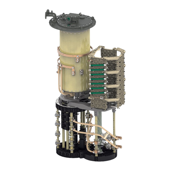
3 Product description 4 Bevel gear 9 Oil conservator 5 Horizontal drive shaft 10 Active part of the transformer 3.1.2 Setup/models The following drawing shows the main components of the on-load tap- changer. You will find a detailed drawing of the on-load tap-changer in the "Drawings [►Section 10, Page 71]"... - Page 17 3 Product description Figure 2: VACUTAP® VRF I 1601/1801 1 On-load tap-changer head 5 Tap selector 2 Upper gear unit 6 Change-over selector (optional) 3 Pipe bend 7 On-load tap-changer head cover 4 Oil compartment 8 Rupture disk ® Maschinenfabrik Reinhausen GmbH 2021 5220960/04 EN VACUTAP VRF I 1601/1801...
- Page 18 3 Product description 3.1.2.1 Pipe connections The on-load tap-changer head features 4 pipe connections for different pur- poses. Depending on the order, some or all of these pipe connections are fitted with pipe bends ex factory. All pipe bends without terminal box for the tap-change supervisory control can be freely swiveled once the pressure ring is loos- ened.
-
Page 19: Nameplate And Serial Number
3 Product description Pipe connection E2 Pipe connection E2 is sealed off with a blank cover. It leads into the oil tank of the transformer, directly under the on-load tap-changer head and can be connected to a collective pipe for the Buchholz relay, if necessary. This pipe connection serves a further purpose, namely to equalize the pressure be- tween the transformer tank and oil compartment of the on-load tap-changer, which is necessary for drying, filling with insulating fluid and transportation of... -
Page 20: Protective Devices
3 Product description 3.1.4 Protective devices The on-load tap-changer is equipped with the following protective devices. 3.1.4.1 Protective relay 3.1.4.1.1 Function description The protective relay is looped into the circuit breaker tripping circuit. It is tripped when the specified speed of flow from the on-load tap-changer head to the oil conservator is exceeded due to a fault. - Page 21 3 Product description Rear view Figure 7: Protective relay RS 2001 1 Dummy plug 2 Nameplate The protective relay RS 2001/R has an extra inspection window on the rear. View from above Figure 8: Protective relay RS 2001 1 Gasket 2 Potential tie-in 3 Terminal box cover 4 Slotted head screw for potential tie-in...
- Page 22 3 Product description 11 Connection terminal 12 Pressure equalization element 13 Cylinder head screw for protective conductor connection The protective relays RS 2003 and RS 2004 have a 1/2"-14NPT adapter in place of the cable gland. 3.1.4.1.3 Nameplate The nameplate is on the back of the protective relay. Figure 9: Nameplate 3.1.4.1.4 Safety markings The following safety markings are used on the product:...
- Page 23 The pressure monitoring device responds to large pressure increases faster than the protective relay. The protective relay is part of the standard MR pro- tection system and comes as standard.
- Page 24 3 Product description The housing and the cover cap of the pressure monitoring device consist of lightweight, corrosion-resistant metal. Figure 11: Snap-action switch and pressure measuring element 1 Snap-action switch 2 Pressure measuring element ® VACUTAP VRF I 1601/1801 5220960/04 EN Maschinenfabrik Reinhausen GmbH 2021...
- Page 25 3.1.4.4 Pressure relief device MPreC® On request, MR will supply a pre-fitted MPreC® pressure relief device in place of the rupture disk. This device responds to a defined overpressure in the oil compartment of the on-load tap-changer.
- Page 26 3 Product description 3.1.4.6 Temperature monitoring The temperature monitoring system monitors the temperature of the insulat- ing fluid in the oil compartment of the on-load tap-changer. ® VACUTAP VRF I 1601/1801 5220960/04 EN Maschinenfabrik Reinhausen GmbH 2021...
-
Page 27: Drive Shaft
3 Product description 3.2 Drive shaft 3.2.1 Function description The drive shaft is the mechanical connection between the drive and the on- load tap-changer/de-energized tap-changer. The bevel gear changes the direction from vertical to horizontal. Accordingly, the vertical drive shaft has to be mounted between drive and bevel gear, and the horizontal drive shaft between bevel gear and on-load tap-changer or de-energized tap-changer. -
Page 28: Design/Versions
3 Product description 3.2.2 Design/versions The drive shaft consists of a square tube and is coupled at each end by two coupling brackets and one coupling bolt to the driving or driven shaft end of the device to be connected. Figure 13: Components of the drive shaft 1 Bevel gear 2 Hose clip... - Page 29 3 Product description 3.2.2.1 Drive shaft without cardan joint and without insulator Figure 14: Drive shaft without cardan joint and without insulator (= standard version) Configuration V 1 min Intermediate bearing Middle of hand crank – middle of 536 mm When the maximum value bevel gear (maximum permissible of 2472 mm is exceeded, it axial offset 2°)
- Page 30 3 Product description 3.2.2.2 Drive shaft without cardan joint and with insulator Figure 15: Drive shaft without cardan joint and with insulator (= special model) Configuration V 1 min Intermediate bearing Middle of hand crank – middle of 706 mm When the maximum value bevel gear (maximum permissible of 2472 mm is exceeded, it axial offset 2°)
- Page 31 3 Product description 3.2.2.3 Drive shaft with cardan joints, without insulator Figure 16: Drive shaft with cardan joints, without insulator (= special model) Configuration V 1 min [mm] Intermediate bearing for [mm] Middle of hand crank – middle of V 1 > 2564 bevel gear (maximum permissible axial offset 20°) ®...
- Page 32 3 Product description 3.2.2.4 Drive shaft with cardan joints, with insulator Figure 17: Drive shaft with cardan joints, with insulator (= special model) Configuration V 1 min [mm] Intermediate bearing for [mm] Middle of hand crank – middle of V 1 > 2772 bevel gear (maximum permissible axial offset 20°) ®...
-
Page 33: Commissioning
4 Commissioning 4 Commissioning WARNING Danger of explosion! Explosive gases in the oil compartment of the on-load tap-changer, trans- former, pipework system, oil conservator and at the dehydrating breather opening can deflagrate or explode and result in severe injury or death! ►... - Page 34 4 Commissioning 2. Establish a connecting lead between pipe connection E2 and one of the pipe connections R, S or Q to ensure equal pressure in the oil compart- ment and transformer during evacuation. Figure 18: Connecting lead between E2 and Q 3.
-
Page 35: Bleeding On-Load Tap-Changer Head And Suction Pipe
4 Commissioning 4.1.2 Bleeding on-load tap-changer head and suction pipe 4.1.2.1 Bleeding on-load tap-changer head 1. Open all forward valves and return valves in the pipe system. 2. Remove screw cap on air-vent valve E1 on the on-load tap-changer head cover. -
Page 36: Checking Motor-Drive Unit
4 Commissioning 4.1.2.2 Bleeding suction pipe on pipe connection S 1. Remove screw cap from pipe connection S. Figure 22: Screw cap NOTICE! An incompletely bled suction pipe significantly impairs the insu- lation capability of the on-load tap changer to ground. Open vent screw and bleed suction pipe completely. -
Page 37: Checking Protective Relay
Tests on the motor-drive unit 1. Perform function checks as described in relevant MR operating instruc- tions for motor-drive unit. NOTICE! An incorrectly coupled motor-drive unit will lead to damage to the on-load tap-changer. -
Page 38: Checking Pressure Monitoring Device
4 Commissioning 4. Loosen the three screws on the terminal box cover and lift off the terminal box cover. 5. Remove the slotted head screw for potential tie-in and remove the termi- nal box cover with wire. 6. Press OFF test button. 7. -
Page 39: Commissioning The Transformer
4 Commissioning 7. Ensure that the transformer's circuit breaker cannot be closed. ð Passive protection test 8. Activate the sensor on the snap-action switch. ð Sensor is in the OPERATION position. 9. Leave the transformer's danger zone. 10. Close the transformer's circuit breaker with isolating switches open and the transformer grounded on all sides. -
Page 40: Operation
5 Operation 5 Operation 5.1 Operating the motor-drive unit with the hand crank WARNING Danger of explosion! Unauthorized operation of the motor-drive unit with the hand crank may re- sult in death or serious injury. ► Never operate the motor-drive unit electrically or with the hand crank be- fore the transformer has been disconnected if you think there may be a fault in the transformer or on-load tap-changer / de-energized tap- changer. - Page 41 5 Operation Operating the motor-drive unit with the hand crank To carry out a tap-change operation with the hand crank, proceed as follows: 1. Open the door of the protective housing for the motor-drive unit. 2. Switch off motor protective switch Q1 (position 0). 3.
-
Page 42: Fault Elimination
In the event of faults on the on-load tap-changer and motor-drive unit which cannot be easily corrected on site, or if the protective relay or additional pro- tective devices have been tripped, please inform your authorized MR repre- sentative, the transformer manufacturer or contact MR directly. - Page 43 If the fill level has fallen below the limit values, also contact MR. On-load tap-changer not changing tap position (sluggish- Contact MR.
-
Page 44: Tripping The Protective Relay And Re-Commissioning The Transformer
6 Fault elimination Fault description Action Red message on monitoring unit If possible read out database and send to MR along with error code. Warning or tripping of Buchholz relay on transformer Notify manufacturer of transformer. Deviation from desired value when measuring winding re-... -
Page 45: Flap Valve In Operation Position
6 Fault elimination 4. Check the on-load tap-changer head cover. If insulating fluid is leaking, close the oil conservator stop valve immediately. 5. Check whether the flap valve of the protective relay is in the OFF or OP- ERATION position. 6.1.1 Flap valve in OPERATION position If the flap valve is in the OPERATION position, there may be a fault in the tripping circuit. -
Page 46: Tripping The Pressure Monitoring Device And Putting The Transformer Back Into Operation
6 Fault elimination 6.2 Tripping the pressure monitoring device and putting the transformer back into operation WARNING Danger of death or severe injury! Danger of severe injury or death if on-load tap-changer and transformer are insufficiently tested. ► Be sure to contact Maschinenfabrik Reinhausen to check on-load tap- changer and transformer after the pressure monitoring device has been tripped. -
Page 47: Sensor In The Off Position
6 Fault elimination 6.2.2 Sensor in the OFF position Proceed as follows if the sensor is in the OFF position. 1. Ensure that the transformer is not started up under any circumstances. 2. Contact and inform Maschinenfabrik Reinhausen of the following: ð... -
Page 48: Maintenance
7 Maintenance 7 Maintenance DANGER Electric shock! An energized transformer could cause death or serious injuries. ► Switch off transformer on high and low-voltage side. ► Lock transformer to prevent unintentional restart. ► Ensure that everything is de-energized. ► Visibly connect all transformer terminals to ground (grounding leads, grounding disconnectors) and short circuit them. -
Page 49: Inspection
7 Maintenance 7.1 Inspection Monitoring the on-load tap-changer and motor-drive unit/control cabinet is limited to occasional visual checks and monitoring the quality of the insulat- ing fluid. For efficiency reasons these visual inspections can be combined with the usual checks on the transformer. Interval Action Annually... -
Page 50: Maintenance Intervals
► Adherence to the following maintenance intervals is mandatory. If you are operating the on-load tap-changer without an MR monitoring sys- tem, the following maintenance intervals shall apply. - Page 51 MR monitoring system issues a maintenance warning. ► In the event of failure or shutdown of the MR monitoring system, observe the maintenance intervals as specified in the maintenance plan without the MR monitoring system.
-
Page 52: Changing The Insulation Fluid
7 Maintenance 7.3 Changing the insulation fluid NOTICE Damage to the on-load tap-changer! Small parts in the oil compartment may block the diverter switch insert, thereby damaging the on-load tap-changer. ► Ensure that parts do not fall into the oil compartment. ►... - Page 53 7 Maintenance 1. Loosen hose clips on protective cover of horizontal drive shaft, remove protective cover. Figure 24: Removing protective cover ® Maschinenfabrik Reinhausen GmbH 2021 5220960/04 EN VACUTAP VRF I 1601/1801...
-
Page 54: Emptying The Oil Compartment And Oil Conservator
7 Maintenance 2. Depending on version, loosen 4 or 6 screws on coupling brackets to upper gear unit and bevel gear. Figure 25: Loosening coupling brackets 3. Remove horizontal drive shaft. Be sure not to lose the coupling bolts. Figure 26: Removing drive shaft 7.3.3 Emptying the oil compartment and oil conservator 1. - Page 55 7 Maintenance 4. Once the gas has been discharged and insulating fluid is flowing out of the air-vent valve, close the air-vent valve. 5. Close the stop-cock between the oil conservator and on-load tap-changer. 6. Open air-vent valve E1 again and extract approximately 5–10 liters of in- sulating fluid via the pipe connection S until the area under the on-load tap-changer head cover is free of insulating fluid.
-
Page 56: Filling The Oil Compartment And Oil Conservator With Fresh Insulating Fluid
7 Maintenance 7.3.4 Filling the oil compartment and oil conservator with fresh insulating fluid NOTICE Damage to the on-load tap-changer! Unsuitable insulating fluids cause damage to the on-load tap-changer. ► Only use insulating fluids [►Section 9.1.2, Page 63] approved by the manufacturer. - Page 57 7 Maintenance 6. Vent the on-load tap-changer head via air-vent valve E1 on the on-load tap-changer head cover. To do this, remove screw cap and lift valve tap- pet with a screwdriver. 7. Seal air-vent valve E1 with screw cap (tightening torque 10 Nm). 8.
-
Page 58: Installing Horizontal Drive Shaft
7 Maintenance 7.3.5 Installing horizontal drive shaft 1. Secure horizontal drive shaft between upper gear unit and bevel gear with coupling brackets and 4 or 6 screws. Refer to the drive shaft operating in- structions for details. Figure 32: Securing drive shaft ®... -
Page 59: Centering On-Load Tap-Changer And Motor-Drive Unit
3. For special design types featuring cardan shafts, be sure to check the ex- pansion bellows and the lubricant reservoir of the cardan shafts. You will find a detailed description of how to fit the drive shaft in the MR op- erating instructions "Drive shaft". - Page 60 7 Maintenance Perform the DC resistance measurement in various on-load tap-changer op- erating positions. You need to distinguish here whether the measured cur- rent is interrupted when changing operating position or not. Status of oil compart- Without interruption in With interruption (mea- ment measured current sured current = 0 A be-...
-
Page 61: Performing Dc Resistance Measurement On Transformer
7 Maintenance 7.4 Performing DC resistance measurement on transformer The measured DC current is normally restricted to 10% of the rated current of the measured transformer winding in order to prevent the winding from overheating. Perform the DC resistance measurement in various on-load tap-changer op- erating positions. -
Page 62: Disposal
8 Disposal 8 Disposal For disposal, observe the national requirements applicable in the country of use. If you have any questions about disassembly and disposal, please contact Maschinenfabrik Reinhausen GmbH's Technical Service department. ® VACUTAP VRF I 1601/1801 5220960/04 EN Maschinenfabrik Reinhausen GmbH 2021... -
Page 63: Technical Data
9 Technical data 9 Technical data An overview of all key technical data for the on-load tap-changer and motor- drive unit exists in the form of separate documents, which are available on request. 9.1 Technical data for on-load tap-changer 9.1.1 On-load tap-changer properties On-load tap-changer VRF I 1601 VRF I 1801... - Page 64 9 Technical data Insulating fluid ▪ Unused insulating oils derived from petroleum products accordance with IEC60296 and ASTM D3487 (equivalent standards on request) ▪ Unused insulating oils derived from other virgin hydrocarbons in accordance with IEC60296, or blends of these oils with pe- troleum products in accordance with IEC60296, ASTM D3487 or equivalent standards on request...
-
Page 65: Technical Data For Protective Relay
9 Technical data 9.2 Technical data for protective relay The technical data for the protective relay RS 2001 is listed in the following. In accordance with DIN EN 60255-1, operational accuracy = base accuracy Housing Outdoor model Degree of protection IP66 Relay actuation Flap valve with aperture... - Page 66 9 Technical data Dielectric strength AC dielectric strength between all volt- 2,500 V, 50 Hz, test duration 1 minute age-carrying connections and the grounded parts AC dielectric strength between the 2,000 V, 50 Hz, test duration 1 minute opened contacts Table 15: Dielectric strength Electrical data for normally open (NO) dry-reed magnetic switch Electrical data...
-
Page 67: Special Models Of Protective Relay
9 Technical data Ambient conditions Ambient temperature Ta -40°C…+50°C Oil temperature <130 °C Air pressure Corresponds to 0 m…4,000 m above sea level Table 19: Ambient conditions 9.3 Special models of protective relay 9.3.1 Protective relay with CO change-over contact as tripping switch The protective relay can be supplied with a dry-reed magnetic switch, CO change-over (variant 3) (see dimensional drawing supplied). -
Page 68: Protective Relay With Several Dry-Reed Magnetic Switches
9 Technical data Dielectric strength AC dielectric strength between all volt- 2,500 V, 50 Hz, test duration 1 minute age-carrying connections and the grounded parts AC dielectric strength between the 1,150 V, 50 Hz, test duration 1 minute opened contacts Table 22: Dielectric strength 9.3.2 Protective relay with several dry-reed magnetic switches The protective relay can be supplied with several independent dry-reed mag-... -
Page 69: Technical Data For Pressure Monitoring Device
9 Technical data 9.4 Technical data for pressure monitoring device General technical data Setup Outdoor model Ambient temperature -40 °C…+80 °C (mechanical) Cable gland M25x1.5 Degree of protection IP55 in accordance with IEC 60529 (enclosed de- vice) Relay actuation Corrugated tubing with counter-pressure spring Oil temperature -40 °C…+100 °C Weight... -
Page 70: Limit Values For Dielectric Strength And Water Content Of Insulating Fluids
9 Technical data 9.5 Limit values for dielectric strength and water content of insulating fluids The following tables specify the limit values for dielectric strength (measured in accordance with IEC 60156) and water content (measured in accordance ® with IEC 60814) of insulating fluids for the VACUTAP on-load tap-changer. -
Page 71: Drawings
10 Drawings 10 Drawings 10.1 Dimensional drawings ® Maschinenfabrik Reinhausen GmbH 2021 5220960/04 EN VACUTAP VRF I 1601/1801... - Page 72 WITH CHANGE-OVER SELECTOR W, G WITHOUT CHANGE-OVER SELECTOR (REVERSING / COARSE CHANGE-OVER SELECTOR) 37,8 1...17 1...17 1...17 1...17 0, +, - 2...18 2...K 0, +, - 2...18 2...K 37,5 REVERSING CHANGE-OVER SELECTOR (1W) COARSE CHANGE-OVER SELECTOR (1G) FOR THE TYPE OF OLTC-HEAD REFER TO THE ORDER-SPECIFIC DRAWING OF THE OLTC-HEAD AND DRIVE SHAFTS 1038,5 - DRIVE SIDE OF SELECTOR...
- Page 73 VACUTAP® VRF SELECTOR SIZE RD / RDE Um [kV] 72,5 123 170 245 300 362 420 72,5 123 170 245 300 362 420 2163 2293 2393 2493 2623 2753 2873 2243 2373 2473 2573 2703 2833 2953 1194 1324 1424 1524 1654 1784...
- Page 74 DIMENSION SERIAL NUMBER SELECTOR SIZE RC/RD/RDE/RE/RF IN mm SELECTOR CONNECTION CONTACT MATERIAL NUMBER SHEET EXCEPT AS DIMENSION DRAWING 100099170E 1 1 / NOTED...
-
Page 75: On-Load Tap-Changer Head
10 Drawings 10.2 On-load tap-changer head ® Maschinenfabrik Reinhausen GmbH 2021 5220960/04 EN VACUTAP VRF I 1601/1801... - Page 76 GASKET WIDTH GROUND CONNECTION M12 37,5 1: 1 E1 = BLEEDING FACILITY FOR ON-LOAD TAP-CHANGER HEAD E2 = BLEEDING FACILITY FOR SPACE UNDER THE HEAD OUTSIDE THE TAP-CHANGER OIL COMPARTMENT (SAME PIPE CONNECTION AS R, S, Q OR BLEEDER SCREW CAN BE USED) Q = CONNECTION FOR OIL RETURN PIPE OR TAP-CHANGE SUPERVISORY CONTROL CONNECTIONS SWIVELING S = CONNECTION FOR SUCTION PIPE...
- Page 77 Um [kV] 170 / 245 / 300 362 / 420 ø56 ø100 DIMENSION [mm] ø620 ø695 O-RING 44,2 - 5,7 LIFTING DEVICE O-RING TRANSFORMER COVER SCREENING RING ONLY WITH Um=170/245/300/362/420 kV O 750 SUPPORTING FLANGE LIFTING DEVICE Z = CENTERING BOLT DRIVE SIDE OF SELECTOR SERIAL NUMBER ON-LOAD TAP-CHANGER VACUTAP®...
- Page 78 O 235 O 152,5 1: 1 GASKET 4,25 x 178,5 x 200 DRIVE SIDE OF SELECTOR MA = 50 Nm O 262 SERIAL NUMBER ON-LOAD TAP-CHANGER DIMENSION IN mm OILTAP® M, MS, R, RM AND VACUTAP® VR®, VM®, VMS® MATERIAL NUMBER SHEET EXCEPT AS...
-
Page 83: Adjustment Plans
10 Drawings 10.3 Adjustment plans ® Maschinenfabrik Reinhausen GmbH 2021 5220960/04 EN VACUTAP VRF I 1601/1801... - Page 84 Laststufenschalterkopf Laststufenschalterkopf mit Verbindlich für die Bezeichnung und Be- stückung der Anschlusskontakte und mit Kopfantrieb / ON-LOAD seitlichem Antrieb / ON-LOAD Phasen ist das Ausführungsschaltbild. / TAP-CHANGER HEAD WITH TAP-CHANGER HEAD WITH THE CONNECTION DIAGRAM OF THE ON- TOP DRIVE SIDE DRIVE LOAD TAP-CHANGER IS BINDING FOR THE DESIGNATION AND THE EQUIPMENT OF THE...
- Page 85 Laststufenschalterkopf Laststufenschalterkopf mit Verbindlich für die Bezeichnung und Be- stückung der Anschlusskontakte und mit Kopfantrieb / ON-LOAD seitlichem Antrieb / ON-LOAD Phasen ist das Ausführungsschaltbild. / TAP-CHANGER HEAD WITH TAP-CHANGER HEAD WITH THE CONNECTION DIAGRAM OF THE ON- TOP DRIVE SIDE DRIVE LOAD TAP-CHANGER IS BINDING FOR THE DESIGNATION AND THE EQUIPMENT OF THE...
- Page 86 Laststufenschalterkopf Laststufenschalterkopf mit Verbindlich für die Bezeichnung und Be- stückung der Anschlusskontakte und mit Kopfantrieb / ON-LOAD seitlichem Antrieb / ON-LOAD Phasen ist das Ausführungsschaltbild. / TAP-CHANGER HEAD WITH TAP-CHANGER HEAD WITH THE CONNECTION DIAGRAM OF THE ON- TOP DRIVE SIDE DRIVE LOAD TAP-CHANGER IS BINDING FOR THE DESIGNATION AND THE EQUIPMENT OF THE...
- Page 88 Maschinenfabrik Reinhausen GmbH Falkensteinstrasse 8 93059 Regensburg +49 (0)941 4090-0 sales@reinhausen.com www.reinhausen.com ® 5220960/04 EN - VACUTAP VRF I 1601/1801 - - 10/21 - Maschinenfabrik Reinhausen GmbH 2021 THE POWER BEHIND POWER.
Need help?
Do you have a question about the VACUTAP VRF I 1601 and is the answer not in the manual?
Questions and answers