
Subscribe to Our Youtube Channel
Related Manuals for Matrox CronosPlus


Summary of Contents for Matrox CronosPlus
- Page 1 Matrox CronosPlus Installation and Hardware Reference Manual no. 10860-101-0100 January 20, 2003 ox Meteor-II /Digital...
- Page 2 © Copyright Matrox Electronic Systems Ltd., 2003. All rights reserved. Limitation of Liabilities: In no event will Matrox or its suppliers be liable for any indirect, special, incidental, economic, cover or consequential damages arising out of the use of or inability to use the product, user...
-
Page 3: Table Of Contents
Matrox CronosPlus hardware reference ........22... - Page 4 Contacting Matrox ........
-
Page 5: Chapter 1: Introduction
Chapter Introduction This chapter outlines the key features of the Matrox CronosPlus board. -
Page 6: Matrox Cronosplus
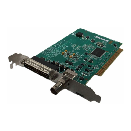
6 Chapter 1: Introduction Matrox CronosPlus Matrox CronosPlus is a standard monochrome and composite color analog frame grabber for extremely cost-sensitive imaging applications. This board is available in a PCI form factor and can acquire different types of standard video formats using its video decoder. -
Page 7: Data Transfer
4 user output TTL signals. Data transfer The Matrox CronosPlus board allows the transfer of live video to Host memory or off-board display memory. Matrox CronosPlus also features a 32-bit/33 MHz PCI bus master to reduce CPU usage. The board can also generate interrupts for the start and end of a field, frame, and sequence capture. -
Page 8: Essentials To Get Started
• Microsoft Windows if using Matrox Imaging software (consult the documentation accompanying the software for specific supported environments and computer memory/storage requirements). ❖ Matrox CronosPlus is not supported under Windows NT. • A CD drive, and a hard disk or network drive on which to install the Matrox CronosPlus software. -
Page 9: Inspecting The Matrox Cronosplus Package
5 BNCs and open-ended wires on the other end. Handling components The electronic circuits in your computer and the circuits on Matrox CronosPlus are sensitive to static electricity and surges. Improper handling can seriously damage the circuits. Be sure to follow these precautions: •... -
Page 10: Installation Overview
Appendix A. 2. Complete the software installation procedure as described in the documentation accompanying your software package. For information on using multiple Matrox CronosPlus boards, refer to Chapter 4, More information and for in-depth hardware information, refer to Chapter 5. -
Page 11: Chapter 2: Hardware Installation
Chapter Hardware installation This chapter explains how to install the Matrox CronosPlus hardware. -
Page 12: Installing Matrox Cronosplus
Matrox CronosPlus board. Five empty (32-bit) PCI slots are illustrated below: 3. If present, remove the blank metal plate located at the back of the selected slot. Keep the removed screw; you will need it to fasten the Matrox CronosPlus board. - Page 13 Installing Matrox CronosPlus 4. Carefully position Matrox CronosPlus in the selected PCI slot. 5. Once perfectly aligned with an empty slot, press the board firmly but carefully into the connector. 6. Anchor the board by replacing the screw that you removed.
-
Page 14: Connecting External Devices To Matrox Cronosplus
Connecting external devices to Matrox CronosPlus Matrox CronosPlus has the following connectors on its bracket. The pinouts of these connectors are discussed in detail in Appendix B. • BNC connector. Used to receive CVBS video input 0 or the Y component of Y/C video input. - Page 15 Connecting external devices to Matrox CronosPlus The wires of the cable for video input are listed in the following table: Wire label Signal Expected input CH-0 VID_IN0 CVBS video input 0 or Y component of Y/C video input. CH-1 VID_IN1 CVBS video input 1.
- Page 16 16 Chapter 2: Hardware installation...
-
Page 17: Chapter 3: Using Multiple Matrox Cronosplus Boards
Chapter Using multiple Matrox CronosPlus boards This chapter explains how to use multiple Matrox CronosPlus boards. -
Page 18: Multiple Board Installation
(refer to Chapter 2). In other words, place each additional board in an empty slot. Theoretically, you can have as many as 16 Matrox CronosPlus boards installed in your computer at one time; this number is, however, limited by the number of empty slots in your computer and, for simultaneous grabs, by the available bandwidth of your computer (discussed later in this chapter). - Page 19 PCI bandwidth of 35 Mbytes/sec or 42 Mbytes/sec, respectively, when transferring in RGBX (32-bit) mode. When grabbing from three or more Matrox CronosPlus boards simultaneously, you will have to reduce the image size to avoid reaching the upper limits of the...
- Page 20 20 Chapter 3: Using multiple Matrox CronosPlus boards...
-
Page 21: Chapter 4: Hardware Reference
Chapter Hardware reference This chapter explains the architecture of the Matrox CronosPlus hardware, as well as the available features and modes. -
Page 22: Matrox Cronosplus Hardware Reference
Matrox CronosPlus hardware reference This chapter provides information on the architecture, operating modes, and supported features of Matrox CronosPlus. For a summary of the information given in this chapter and detailed specifications of connectors and pinouts, refer to Appendix B of this manual. -
Page 23: Grab Features
Grab features Grab features The Matrox CronosPlus board is equipped with a video decoder chip that has an integrated PCI interface. The chip can grab RS-170 /CCIR monochrome video and composite (CVBS) and component (Y/C) video in NTSC /PAL format. -
Page 24: Low-Pass Filter
Low-pass filter The input low-pass filtering stage is used to limit high frequency noise and aliasing effects at the input of the decoder. The filters used on Matrox CronosPlus are 4th order Butterworth filters with a cut-off frequency of 8 MHz. -
Page 25: User Bits
Electrical specifications in Appendix B. PCI interface Matrox CronosPlus has a 32-bit PCI bus interface, which is capable of a peak transfer rate of 132 Mbytes/sec, and operates at 33 MHz. Matrox CronosPlus uses an internal FIFO to buffer image data while waiting to access the PCI bus. - Page 26 26 Chapter 4: Hardware reference...
-
Page 27: Appendix A: Troubleshooting
Appendix A: Troubleshooting This appendix gives suggestions to help you resolve potential problems. If your problem is not addressed here, contact your local Matrox representative, Matrox Sales Office, or the Matrox Imaging Customer Support Group. -
Page 28: Troubleshooting
Installation Problems ➘ You receive a "Board service fails to start" error upon booting your computer, or you receive a "Driver has not started" error upon allocating a MIL CronosPlus system. This could happen due to the following three reasons: - The MIL Matrox CronosPlus drivers are not installed correctly. -
Page 29: Grabbing Problems
Resources folder. Then, display the subfolder \Memory to check if any of the memory address ranges overlap. After, in the case of Me, display the subfolder \IRQs to check for devices that are sharing an IRQ with your Matrox frame grabber. In general, PCI devices can share an interrupt line (IRQ). However, sometimes this might not be possible. -
Page 30: Contacting Matrox
30 Appendix A: Troubleshooting - Re-assign a different IRQ line to the PCI slot in which the Matrox CronosPlus board is installed. Note that PCI devices cannot share interrupt lines with EISA or ISA devices. - Move the Matrox CronosPlus board to another (free) PCI slot. -
Page 31: Appendix B: Technical Information
Appendix B: Technical information This appendix contains information that might be useful when installing your Matrox CronosPlus board. -
Page 32: Technical Information
(or equivalent) or better. Some older systems use a core logic chipset (interfaces PCI with Host memory) that has limited throughput capabilities. Matrox CronosPlus might not be able to attain full functionality on such systems. We recommend systems with newer PCI chipsets, such as the Intel 440BX, 810, 815E, 820, 840, or 850. -
Page 33: Electrical Specifications
Electrical specifications Electrical specifications Operating voltage and current (typical) Voltage Current Power 5 V ± 5% 500 mA 2.5 W -5 V ± 5% 3.3 V± 5% 12 V ± 10% 25 mA 0.30 W -12 V ± 10% Total 2.80 W Signals Specifications... -
Page 34: Environmental Specifications
34 Appendix B: Technical information Environmental specifications • Min./max. ambient operating temperature: 10°C - 60° C. • Min./max. storage temperature: -45° C - 115° C. • Max. altitude for operation: 3000 meters. • Max. altitude for transport: 12000 meters. • Operating humidity: 20 - 80% relative humidity (non-condensing). -
Page 35: Board Connectors
Board connectors Board connectors The Matrox CronosPlus board has a BNC video input connector and a 25-pin video input connector on its bracket. BNC connector The BNC connector is used to receive CVBS video input 0 or the Y component of Y/C video input. -
Page 36: Video Input Connector
36 Appendix B: Technical information Video input connector The video input connector is a standard 25-pin, D-SUB male connector that is located on the module’s bracket.The connector is used receive video input, send or receive user signals, and receive a trigger input signal. Pin 1 Pin 13 Pin 14... -
Page 37: Appendix C: Glossary
Appendix C: Glossary This appendix defines some of the specialized terms used in this Matrox CronosPlus document. - Page 38 38 Appendix C: Glossary • AGC Automatic Gain control. Used to keep the output signal of a circuit constant as the input signal amplitude varies. • Bandwidth A term describing the capacity to transfer data. Greater bandwidth is needed to sustain a higher transfer rate.
- Page 39 • Horizontal sync The part of a video signal that indicates the end of a line and the start of a new one. See also vertical sync. • Host In general, Host refers to the principal CPU in one’s computer. •...
- Page 40 40 Appendix C: Glossary • Progressive scanning Describes a transfer of data in which the lines of the source input device are written sequentially into the destination buffer. Also known as non-interlaced. See also interlaced scanning. • Real-time processing The processing of an image as quickly as the next image is grabbed. Also known as live processing.
-
Page 41: Index
Index low-pass filter 24 Matrox CronosPlus package ActiveMIL 7 optional items 9 automatic gain control 24 standard package 9 Matrox Inspector 7 Matrox Intellicam 8 MIL 7 cameras MIL-Lite 7 number of cameras per board 18 multiple boards 18 conventions 10... - Page 42 – video decoder 23 video formats supported monochrome 6 NTSC 6 PAL 6 Y/C 6...
-
Page 43: Regulatory Compliance
Attention: Conformity Group Matrox Declaration The Matrox hardware products supported by this guide comply with Part 15 of the FCC Rules. Operation is subject to the following two conditions: (1) these devices may not cause harmful interference, and (2) these devices must accept any interference received, including interference that may cause undesired operation. - Page 44 (English) Industry Canada Compliance Statement Remark for the Matrox hardware products supported by this guide These digital devices do not exceed the Class B limits for radio noise emission from digital apparatus devices set out in the Radio Interference Regulation of Industry Canada.
- Page 45 (Español) Información para usuarios europeos – Declaración de conformidad Observación referente a los productos de hardware de Matrox apoyados por este manual Estos dispositivos cumplen con la directiva de la CE 89/336/EEC para dispositivos digitales de Clase B. Dichos dispositivos han sido sometidos a prueba y se ha comprobado que cumplen con las normas EN55022/CISPR22 y EN55024/CISPR24.
-
Page 46: Product Support
Product support Limited Warranty Matrox warrants this product against defects in materials and workmanship for a period of one year from the date of delivery. Matrox and its suppliers expressly disclaim any and all other warranties, express or implied. Your sole remedy shall be, repair or replacement of the product provided that the defective product be returned to the authorized dealer within a year from the date of delivery. - Page 47 Resolution: Network Card: Network Software: Other cards in system: Software Specific Information Operating system: Rev: Matrox SW used: Rev: Compiler: Rev: Fill out only if you are returning a board RMA #: Who were you talking to in customer support?
- Page 48 Describe the problem:...
Need help?
Do you have a question about the CronosPlus and is the answer not in the manual?
Questions and answers