Burkert 8746 Operating Instructions Manual
Mass flow meter (mfm) / mass flow controller (mfc)
Hide thumbs
Also See for 8746:
- Operating instructions manual (75 pages) ,
- Additional instructions (10 pages) ,
- Operating instructions manual (71 pages)
Table of Contents
Advertisement
Quick Links
Advertisement
Table of Contents

Related Manuals for Burkert 8746


Summary of Contents for Burkert 8746
- Page 1 Type 8746 Profibus Analogue Mass Flow Meter (MFM) / Mass Flow Controller (MFC) Massendurchflussmesser (MFM) / Massendurchflussregler (MFC) Débitmètre massique (MFM) / Régulateur de débit massique (MFC) Operating Instructions Bedienungsanleitung Manuel d‘utilisation...
- Page 2 We reserve the right to make technical changes without notice. Technische Änderungen vorbehalten. Sous réserve de modifications techniques. © Bürkert SAS, 2020 - 2021 Operating Instructions 2103/01_EU-ML_00573732 / Original EN...
-
Page 3: Table Of Contents
Type 8746 Profibus, 8746 Analogue Table of contents The OperaTing insTrucTiOns ..........6 Technical daTa ............... 17 1.1 Definition of the term product ........6 6.1 Conformity ..............17 1.2 About NAMUR and the NAMUR Recommen- 6.2 Standards ..............17 dation NE 107 ..............6 6.3 Operating conditions ........... 17 1.3 Symbols used ..............6 6.3.1... - Page 4 Type 8746 Profibus, 8746 Analogue 10.3 Tools for doing settings ..........41 fluid insTallaTiOn ............27 10.4 Connect the product to the Bürkert Communi- 7.1 Safety instructions ............27 cator software .............. 41 7.2 Installation steps ............28 10.5 User-defined adjustment ..........42 7.3 Product variant with G-internal-threaded fluid 10.6 Operating modes of an MFC ........42 connections ..............28 10.7 Normal operating mode (MFC) ........43 7.4 Product variant with NPT-internal-threaded con- nections ...............
- Page 5 Type 8746 Profibus, 8746 Analogue 12.1.4 Product status indicator is red (MFC non-zero mass flow rate is measured (MFC) . 54 Profibus) ............50 12.3.12 Set-point value is not reached (MFC) .... 54 12.1.5 Product status indicator is orange (MFM) ..50 13 accessOries, spare parTs ......... 55 12.1.6 Product status indicator is orange (MFC) ..51 13.1 Electrical accessories ..........55 12.1.7 Product status indicator is yellow (MFM) ..51 13.2 Compression fittings for a product variant with 12.1.8 Product status indicator is yellow (MFC) ..51 internal-threaded fluid connections ......
-
Page 6: The Operating Instructions
Type 8746 Profibus, 8746 Analogue The Operating instructions The OPerATing insTrucTiOns Symbols used The Operating Instructions describe the entire life cycle of the DANGER product. Please keep the Operating Instructions in a safe place, Warns of an immediate danger. accessible to all users and any new owners. ▶ Failure to observe the warning results in death or in serious important safety information. injuries. ▶ Read the Operating Instructions. If you do not understand the content of the Operating Instructions, then contact Bürkert. -
Page 7: Intended Use
Indicates a result. dry gases. menu Designates a text of a user interface. MFC Type 8746 Profibus or MFC Type 8746 Analogue is used exclusively to regulate the mass flow rate of clean and dry gases. ▶ Observe the data in the contract documents, in the Operating... -
Page 8: Product Variant With Atex Certification
Type 8746 Profibus, 8746 Analogue Basic safety information Product variant with ATEX BASic SAfETy iNfoRMATioN certification This safety information does not take into account any contin- gencies or occurrences that may arise during installation, use DANGER and maintenance of the product. risk of explosion that is due to improper use of the product The operating company is responsible for the respect of the local in potentially explosive areas. safety regulations including for the personnel safety. ▶ Observe the specifications of the ATEX-conformity certificate. - Page 9 Type 8746 Profibus, 8746 Analogue Basic safety information NOTICE Various dangerous situations. To avoid personal injury, obey the following instructions: components or assemblies at risk from electrostatic ▶ Do not operate the product without its mesh filter. charges. ▶ Only operate the product in the installation position that is The product contains electronic components which are suscep- given on the calibration plate. tible to electrostatic discharge (ESD). Contact with electrostati- ▶ Make sure that the operating pressure of the MFM is not cally charged persons or objects endangers these components. higher than the maximum calibration pressure that is given In the worst case, they will become defective immediately or will on the calibration plate. fail when energised. ▶ Make sure that the operating pressure of the MFC is not • To minimise or even avoid any damage caused by an elec- higher than the tight sealing pressure of the control valve.
-
Page 10: General Information
Type 8746 Profibus, 8746 Analogue General information GENERAl iNfoRMATioN contact The name of the manufacturer is displayed as inset writing on the cover and the housing of the product. To contact the manufacturer of the product, use the following address: Bürkert SAS Rue du Giessen F-67220 TRIEMBACH-AU VAL The addresses of our international sales offices are available on the internet at: country.burkert.com Warranty The warranty is conditional on compliant use of the product in observance of the operating conditions specified in the Oper- ating Instructions. information on the internet Operating Instructions and data sheets for the product can be found online at: country.burkert.com English... -
Page 11: Description
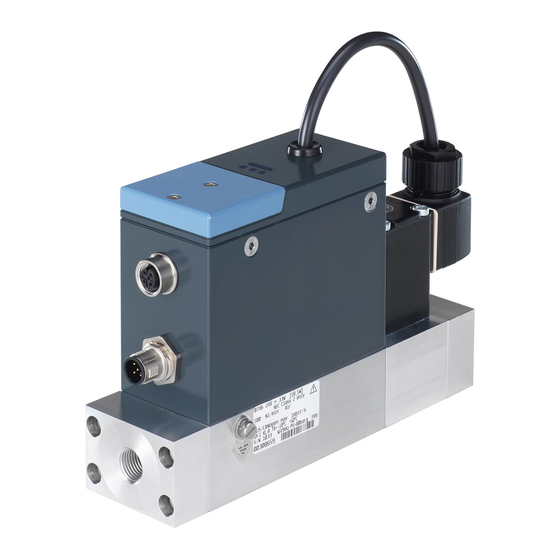
Type 8746 Profibus, 8746 Analogue Description descriPTiOn 2. Electrical connection: 5-pin M12 male connector, A coding 3. Possible fluid connections: Product variants - G-internal-threaded connections according to DIN ISO 228/1 5.1.1 Mass flow Meter (MfM) - NPT-internal-threaded connections according to ASME/ ANSI B 1.20.1 - flange connection 4. M4 screw for functional earth connection 5. Base block 6. Flow direction 7. Product status indicator. The indicator operates according to NAMUR NE 107. 8. Not used 9. Status LED for the fieldbus communication 10. Not used 11. -
Page 12: Mass Flow Controller (Mfc) With Proportional Valve
Type 8746 Profibus, 8746 Analogue Description 5.1.2 Mass flow controller (Mfc) with 3. Possible fluid connections: proportional valve - G-internal-threaded connections according to DIN ISO228/1 - NPT-internal-threaded connections according to ASME/ ANSI B 1.20.1 - flange connection 4. M4 screw for functional earth connection 5. Base block 6. Flow direction 7. Proportional valve. The proportional valve can be built inside the product. 8. Product status indicator. The indicator operates according to NAMUR NE 107. 9. Not used 10. Status LED for the fieldbus communication 11. Not used 12. -
Page 13: Mass Flow Controller (Mfc) With Motor Valve
Type 8746 Profibus, 8746 Analogue Description 5.1.3 Mass flow controller (Mfc) with 3. Possible fluid connections: motor valve - G-internal-threaded connections according to DIN ISO228/1 - NPT-internal-threaded connections according to ASME/ ANSI B 1.20.1 - flange connection 14 13 4. M4 screw for functional earth connection 5. Base block 6. Flow direction 7. Motor valve. 8. Status LED for the motor valve. 9. Product status indicator. The indicator operates according to NAMUR NE 107. 10. Not used 11. - Page 14 Type 8746 Profibus, 8746 Analogue Description • Whether product diagnostics are active or not. Diagnostics are active on the product and cannot be deactivated. • If product diagnostics are active, then the product status indicator shows whether diagnostics events have been generated or not. If several diagnostics events have been generated, then the product status indicator shows the diagnostics event with the highest priority. Refer to Tab. 1. If the product status indicator flashes, then the product is selected in a man-machine interface such as the Bürkert Communicator software. Tab. 1: Product status indicator in accordance with NAMUR NE 107, edition 2006-06-12, for active diagnostics colour colour code diagnostics event meaning for the product according to (for a plc) according to NE 107...
-
Page 15: Motor Valve Status Led
Type 8746 Profibus, 8746 Analogue Description Motor valve status lED Status lED for the fieldbus communication The colour and status of the motor valve status LED give the fol- lowing pieces of information: A product variant Profibus has an LED to show the status of the • Whether the motor valve faces a problem or not. connection to the network. • Whether the motor valve is completely open or closed. Tab. 2: Status of the motor valve depending on the colour of the status Status LED for the fieldbus communication... -
Page 16: Memory Card
Type 8746 Profibus, 8746 Analogue Description Memory card control valve of an Mfc The MFC is equipped with one of the following control valve types: NOTICE • A direct-acting and normally-closed proportional valve. If the memory card is defective or lost, then buy a new memory • A motor-driven valve that is called motor valve. If de-energised, card from your Bürkert sales office. the motor valve remains in its latest position. The product is delivered with a memory card that is inserted in The control valve provides the sealing function when the fol- the product. lowing conditions are met: When the product is energised, there are two possibilities: • The product is used within the specified pressure range. -
Page 17: Technical Data
Type 8746 Profibus, 8746 Analogue Technical data TechnicAl dATA 6.3.1 Mass flow Meter Tab. 4: Operating conditions of an MFM conformity Ambient temperature –10 °C...+50 °C The product complies with the EU directives according to the EU • –10 °C...+70 °C Fluid temperature declaration of conformity (if applicable). • –10 °C...+60 °C for oxygen Standards Ambient humidity < 95%, non-condensing Protection class IP65 The applied standards, which verify conformity with the EU direc- according to If the following conditions are met: tives, can be found on the EU type examination certificate and/or EN 60529 the EU declaration of conformity (if applicable). -
Page 18: Mass Flow Controller With Proportional Valve
Type 8746 Profibus, 8746 Analogue Technical data 6.3.2 Mass flow controller with proportional 6.3.3 Mass flow controller with Type 3280 valve motor valve Tab. 5: Operating conditions of an MFC with proportional valve Tab. 6: Operating conditions of an MFC with Type 3280 motor valve •... -
Page 19: Mass Flow Controller With Type 3285 Motor Valve
Type 8746 Profibus, 8746 Analogue Technical data Markings 6.3.4 Mass flow controller with Type 3285 motor valve WARNING Tab. 7: Operating conditions of an MFC with Type 3285 motor valve Risk of injury caused by pressure, fluid escape. • –10 °C...+50 °C... -
Page 20: Type Label
Type 8746 Profibus, 8746 Analogue Technical data 6.4.2 Type label 10. Product article number 11. Serial number 12. Category of the product 874x 24V ... 9W [5,5W] 13. Product variant Profibus: communication interface IP65/IP67 NEC Class 2 only Product variant Analogue: input and output 5,0 Nl/min Air 10,0 Nl/min Air 14. Nominal flow rate (Qnominal), units and operating gas 2 PROFIBUS DPV1 max.12Mbit/s GR:1 KL:A Ta=-10°C..+50°C 15. -
Page 21: Product Materials
Type 8746 Profibus, 8746 Analogue Technical data Product materials fluid data 6.7.1 Mass flow Meter Tab. 8: Product materials, common to all product variants product part material Tab. 12: Fluid data, MFM • Aluminium Base block Calibration fluid Operating gas or air • Stainless steel 1.4305 Mass flow-rate range 20...2500 I... -
Page 22: Mass Flow Controller With Proportional Valve
Type 8746 Profibus, 8746 Analogue Technical data 6.7.2 Mass flow controller with proportional 6.7.3 Mass flow controller with motor valve valve Tab. 14: Fluid data, MFC with motor valve Calibration fluid Operating gas or air Tab. 13: Fluid data, MFC with proportional valve Calibration fluid... -
Page 23: Quality Of The Operating Fluid
Type 8746 Profibus, 8746 Analogue Technical data 6.7.4 Quality of the operating fluid 6.7.5 Pressure loss (MfM) Use the operating fluid that is given on the product Type-label. A Mass Flow Meter has a pressure loss that depends on the fol- The operating fluid must be clean and dry. lowing parameters: • the flow-rate value The gas or gas mixture must obey the quality criteria in Tab. 15. The quality criteria are given in standard • the size of the product fluid-connections ISO 8573-1, Compressed Air - Part 1: Contaminants and • the type of the product fluid-connections purity classes. The operating gas must obey the quality • the size of the product base-block criteria to obey the following requirements: • the type of operating gas • the necessary measurement accuracy of the product → Determine the pressure-loss value depending on whether the •... - Page 24 Type 8746 Profibus, 8746 Analogue Technical data ∆p [mbar] ∆p [mbar] Example 0 100 1100 1300 1500 1000 1200 1400 Q [l /min] A: MFM with a base block for the 0...100 l /min flow-rate range B: MFM with a base block for the 100...500 l /min flow-rate range C: MFM with a base block for the 500...1500 l /min flow-rate range 1500 1700 1900 2100 2300 2500 Q [l /min]...
-
Page 25: Operating Gas Is Not Air
Type 8746 Profibus, 8746 Analogue Technical data 6.7.7 operating gas is not air Example for argon gas that flows through an MFM with 1/2" internal-threaded fluid connections: If the operating gas is not air, determine the pressure loss as 1. If the flow rate is 1400 l /min then the air pressure-loss p follows: as given in Fig. 8 is 140 mbar. 1. Read the air pressure-loss p from the diagrams in Fig. 8 or 2. The pressure loss for argon gas at a flow rate of 1400 l /min in Fig. 9. is 164.4 mbar as given by the calculation in Fig. 11. 2. Calculate the pressure loss p with the formula that is given in Fig. 10. 1.784 = 140 mbar = 164.4 mbar 1.294 ρ... -
Page 26: Electrical Data
Type 8746 Profibus, 8746 Analogue Technical data Electrical data Tab. 17: Electrical data of an MFC Operating voltage 24 V DC ±10% 6.8.1 Product variant Analogue (15 V DC ±10% on request); residual ripple < 2 % WARNING Maximum power Refer to the Type label consumption ▶ For UL-certified components, only use limited power circuits Set-point analogue input of "NEC Class 2". • 0/4...20 mA • Maximum input impedance: 200 W Tab. 16: Electrical data of an MFM Resolution: 5 µA... -
Page 27: Product Variant Profibus
Type 8746 Profibus, 8746 Analogue Fluid installation Fluid insTAllATiOn 6.8.2 Product variant Profibus WARNING Safety instructions ▶ For UL-certified components, only use limited power circuits DANGER of "NEC Class 2". risk of injury that is due to pressure in the installation or in Tab. 18: Electrical data of an MFM the product. -
Page 28: Installation Steps
Type 8746 Profibus, 8746 Analogue Fluid installation Product variant with G-internal- NOTICE threaded fluid connections Risk of breakage of a product with motor valve. • Do not use the actuator housing of the motor valve as a lever WARNING arm. risk of injury that is due to leakage. Vibrations have an unwanted effect on the control valve ▶ At a low mass flow rate and a high pressure, make sure of the MFC. - Page 29 Type 8746 Profibus, 8746 Analogue Fluid installation No inlet section is required. Tab. 21: Stainless steel compression fittings and related seals product inter- article number The connection to the pipe is explained for one side of the product. nal-threaded The same procedure applies on the other side of the product. pipe connections in stainless steel seal diameter → Remove all dirt from the pipes and from the fluid carrying accordance with compression-fitting (1 piece) components of the installation. din isO 228/1 →...
- Page 30 Type 8746 Profibus, 8746 Analogue Fluid installation → Slide the nut [a] and then the ferrule onto the pipe. See Fig. ferrule Fig. 15: Nut screwed by hand → Tighten the nut with an open-end spanner to a torque of 25...28 N·m, that is 18.44...20.65 lbf·ft. See Fig. 16. Fig. 13: Nut and ferrule on the pipe → Place the seal [C] on the product fluid-connection. → Screw the compression-fitting body [B] in the fluid con- nection. Tighten to a torque of 25...28 N·m, that is 18.44...20.65 lbf·ft. See Fig. 14. Fig. 16: Nut tightened with an open-end spanner →...
-
Page 31: Product Variant With Npt-Internal- Threaded Connections
Type 8746 Profibus, 8746 Analogue Fluid installation Product variant with NPT-internal- NOTICE threaded connections malfunction that is due to contamination. ▶ If a contaminated operating fluid is used, then install a WARNING filter upstream of the product. The filter mesh-size must be smaller than 25 µm. The filter ensures problem-free function- risk of injury that is due to leakage. ing of the product. See chpt. 6.7 Fluid data. ▶ At a low mass flow rate and a high pressure, make sure → Observe the installation position that is given on the cali- that the installation is tight. The tightness prevents incorrect measurements or the leakage of the operating fluid. -
Page 32: Product Variant With Flange Connections
Type 8746 Profibus, 8746 Analogue Electrical installation Product variant with flange elecTricAl insTAllATiOn connections Safety instructions WARNING DANGER risk of injury that is due to leakage. risk of injury from electric shocks. At a low mass flow rate and a high pressure, make sure that ▶ Before working on the installation or the product, switch off the installation is tight. The tightness prevents incorrect meas- the power supply. Make sure that nobody can switch the urements or the leakage of the operating fluid. power supply on. ▶ Observe all applicable accident protection and all applicable Vibrations have an unwanted effect on the control valve safety regulations for electrical equipment. -
Page 33: Additional Documentation
Type 8746 Profibus, 8746 Analogue Electrical installation 8.2.2 Product variant Profibus WARNING • Product-specific help in the Bürkert Communicator software Risk of injury from electromagnetic fields. • For an ATEX product variant: ATEX supplement for Type 8746 If the functional earth (FE) is not attached, then the requirements (download from country.burkert.com). of the EMC directive are not met. • Product description file and object description for the related ▶ Connect the housing to the functional earth (FE). Use a green- product Type must be downloaded from country.burkert.com and-yellow cable that is as short as possible. And the cable cross-section must be at least equal to the cross section of Wiring the product variant the power supply cable. Analogue NOTICE To wire the product, you can use mating male or female con- requirements for the proper function of the product. - Page 34 Type 8746 Profibus, 8746 Analogue Electrical installation → Screw the mating female connector to the 5-pin male connector, Pin Assignment to the torque that is given by the manufacturer of the mating GND for the ana- female connector. logue output → Wire the mating male connector according to the pin assignment Coding lug 24 V of the M12 female connector in Fig. 20. Observe the instructions that are given by the manufacturer of the mating male connector. Not connected Pin Assignment Analogue output GND for the digital for the measured input M12 thread is internally connected to FE value Digital input + Fig. 18: MFM Analogue: Pin assignment, 5-pin M12 male connector (A...
-
Page 35: Digital Input
Type 8746 Profibus, 8746 Analogue Electrical installation 8.3.1 Digital input The 5-pin M12 female connector has a digital input. A digital input is used to remotely trigger a function. The following functions are available: • MFC: Start the function autotune. • MFC: Trigger the remote control of the actuator or trigger the control of the actuator by the product. • MFM or MFC: Reset the totaliser for the active gas. • MFM or MFC: Select which gas is active among 3 gases. Tab. 23 shows the function that is assigned by default to the digital input of the 5-pin M12 female connector of an MFM or an MFC. Tab. 23: Default assignment of the digital input of the 5-pin M12 female connector product variant analogue... -
Page 36: Relay Output
Type 8746 Profibus, 8746 Analogue Electrical installation Tab. 24: Actions triggered by the switching levels Action depending on the activated switching level Level 1 Level 2 Level 3 Activation: Activation: Activation: Short-circuit the digital input 1...4 V DC 5...28 V DC Function with the digital-input ground (alternatively: not connected) MFC: start autotune Triggers the function Not used Not used Triggers the closing of the Triggers the normal operating Triggers the opening of the MFC: actuator control actuator mode... -
Page 37: Wiring The Product Variant Profibus
Type 8746 Profibus, 8746 Analogue Electrical installation → To choose the events that are assigned to the relay output, use → To wire the mating female connector, refer to the pin assignment the Bürkert Communicator software. To connect the product to of the M12 male connector in Fig. 21. Observe the instruc- the Bürkert Communicator software, refer to chpt. 10.4. Several tions that are given by the manufacturer of the mating female events can be associated to the relay output. connector. Pin Assignment Wiring the product variant Profibus Shielding To wire the product, you can use mating male or female con- 24 V Coding lug nectors from Bürkert. Refer to Tab. 26. Not Tab. -
Page 38: Connecting The Functional Earth
Type 8746 Profibus, 8746 Analogue Electrical installation Pin Assignment M4 screw 5 V RxD / TxD (line A) DGND RxD / TxD Fig. 23: Location of the M4 screw for the connection of the functional- earth cable (line B) Coding lug → Attach the functional-earth green-and-yellow cable to the M4 Not screw with a cable lug. connected M12 thread is internally connected to FE → Tighten the M4 screw to a torque of 1,8 N·m...2 N·m, that is Fig. -
Page 39: Commissioning
Type 8746 Profibus, 8746 Analogue Commissioning coMMiSSioNiNG If the inserted memory card is empty, then the product loads its own data on the memory card. Possible problems related to Safety instructions the memory card are given in chpt. 12.3.4 and chpt. 12.3.5. NOTICE WARNING If the memory card is defective or lost, then buy a new memory risk of injury from improper commissioning and operation. card from your Bürkert sales office. Improper commissioning and operation can lead to injuries and 5. If the product is an MFC, and the operating fluid is not the damage to the product and its environment. calibration fluid or the pressure conditions have changed, ▶ Before commissioning, make sure that the operating person- then run the Autotune function. See chpt. 10.8 Optimise the nel are familiar with, and fully understand the content of the closed-loop control parameters (MFC). Operating Instructions. The product operates normally. ▶ Observe the safety information and the intended use. ▶ Only properly trained personnel may commission the instal- lation and the product. -
Page 40: Setting And Operation
Type 8746 Profibus, 8746 Analogue Setting and operation seTTing And OPerATiOn WARNING risk of injury that is due to improper operation. 10.1 Safety instructions Improper operation can lead to injuries and damage to the product and its environment. DANGER ▶ The operating personnel must have read and understood the risk of injury that is due to pressure in the installation or in content of the Operating Instructions. -
Page 41: Flush Mode (Mfc Profibus)
Type 8746 Profibus, 8746 Analogue Setting and operation 10.4 connect the product to the Bürkert 10.2.2 flush mode (Mfc Profibus) communicator software NOTICE To do the settings with the Type 8920 Bürkert Communicator If the control valve is fully open, then the internal product temper- software, do the following steps: ature increases. And if the internal product temperature increases, → Buy the USB-büS-interface set with article number 00772551 then the product can be damaged. from Bürkert. • Do not let the control valve fully open for more than → Download the latest version of the Type 8920 Bürkert Com- 10 minutes. municator software from country.burkert.com To open the control valve completely, send one of the following →... -
Page 42: User-Defined Adjustment
Type 8746 Profibus, 8746 Analogue Setting and operation 10.6 operating modes of an Mfc → Energise the product. Refer to chpt. 8 Electrical installation. → Insert the micro-USB connector into the büS-interface for the When energising the product for the first time, the product enters a Bürkert Communicator software. The location of the büS-in- short initialisation phase and then switches to the normal operating terface on the product is given in chpt. 5.1. mode. The normal operating mode is described in chpt. 10.7. → Wait until the Windows pilot of the büS stick has been com- The possible operating modes are described in Tab. 27. pletely installed on the PC. Tab. 27: Names of the operating modes of an MFC in the Bürkert →... -
Page 43: Normal Operating Mode (Mfc)
Type 8746 Profibus, 8746 Analogue Setting and operation 10.7 Normal operating mode (Mfc) The sensor measures the mass flow rate and compares the measured value x with the set-point value w. Then the product The normal operating mode is active when energising the product calculates the set-point position value y of the control valve. The for the first time. Fig. 25. shows the normal operating mode of an set-point position value y determines the opening of the control MFC. valve. For example, if the set-point position value y is equal to 10%, then the opening of the control valve is 10%. NOTICE The transmission means of the set-point value w and the measured if the valve seat seal is made of a hard material such as value of the flow rate depend on the product. Refer to chpt. 10.7.1 pcTfe, then the control valve may not be tight. -
Page 44: Optimise The Closed-Loop Control Parameters (Mfc)
Type 8746 Profibus, 8746 Analogue Setting and operation analog set-point value operating mode. WARNING • The set-point value w is transmitted over the set-point ana- Risk of injury from flowing gas. logue input according to the ranges in Tab. 28. While the Autotune function is running, the gas flow can be • The measured value of the flow rate is transmitted over the higher than the nominal flow. analogue output according to the ranges in Tab. 28. ▶ Before running the Autotune function, make sure that no Tab. 28: Analogue-input ranges and analogue-output ranges danger can occur if the gas flow increases. Analogue Minimum value of the Maximum value of the →... -
Page 45: Choose The Source Giving The Set-Point Value (Mfc)
Type 8746 Profibus, 8746 Analogue Setting and operation 10.9 choose the source giving the set- overwritten by other fieldbus participants. point value (Mfc) • stored set-point value: to use a fixed set-point value (w). When the product is restarted the fixed set-point value remains The process set-point value can be set by different sources. You active. can choose which source is active at a time. The source for the • Open-loop control mode: to directly set the set-point position set-point value can be changed during operation. (y) to the control valve. The value that is given in the menu If you change the source for the set-point value, then the operating actuator parameter actuating variable is mode of the MFC is changed. -
Page 46: Maintenance
Type 8746 Profibus, 8746 Analogue Maintenance MAiNTENANcE Download the initiation files and the related documentation at country.burkert.com. If no heavily contaminated fluids are used and if the product is operated according to the Operating Instructions, then the product is maintenance-free. 11.1 Maintenance for operation with heavily contaminated fluids DANGER risk of injury that is due to pressure in the installation or in the product. -
Page 47: Inspect And Clean The Stainless Steel
Type 8746 Profibus, 8746 Analogue Maintenance chpt. 13 Accessories, Spare Parts. WARNING 11.1.1 inspect and clean the stainless steel mesh-filter Risk of injury that is due to improper maintenance work. ▶ Only trained personnel can do the maintenance work. Per- The inspection and possibly cleaning of the stainless steel mesh- sonnel must use suitable tools. filter must be done at regular intervals. The inspection frequency ▶ Secure the installation against unintentional actuation. and cleaning frequency depend on the measured fluid. ▶ Ensure a controlled restart after maintenance. Reverse side of the flange plate, WARNING with inserted O-ring if you open the housing, risk of injury from malfunction and risk of product failure. -
Page 48: Cleaning And Recalibration At The Factory
Type 8746 Profibus, 8746 Analogue Maintenance 11.2 cleaning and recalibration at the → With an hexagon key of size 3 mm, loosen the screws [1] and remove the flange plate [2]. The O-ring [3] remains in the factory groove on the rear side of the flange plate. If the product sensor is contaminated or damaged by operation, → With a pair of tweezers, remove the circlip [4] because the then the measured mass flow rate could no longer correspond to mesh filter [6] and the ring [5] will be pushed out by the com- the actual mass flow rate. pression spring [7]. → Send the product back to the manufacturer because the sensor must be replaced and recalibrated. Observe the return → Do not clean the mesh filter with tap water. procedure in chpt. 17 Returning the product. → Clean the stainless steel mesh-filter [4] with acetone, isopro- 11.3 Replace the memory card panol or compressed air. → Dry the mesh filter. -
Page 49: Troubleshooting
The product status indicator changes its colour based on the NAMUR recommendation NE 107 to show diagnostics events. If several diagnostics events have been generated, then the Inserted memory card product status indicator shows the diagnostics event with the highest priority. If the product is connected to a fieldbus, then the codes that are related to the product states are transmitted on the fieldbus. Refer Fig. 28: Cross-sectional drawing of a product Type 8746 to chpt. 5.2. → Fit the cover back. 12.1.1 Product status indicator is red (MfM → If an ATEX product is used in a potentially explosive area, Analogue) then fit the impact protection-cover back. → With a TX8 key for hexalobular-internal screw, tighten the Identify the cause to solve the problem: cover screws to a torque of 1.2 N·m, that is 0.9 lbf·ft. 1. The supply voltage is out of the error range. The product can →... -
Page 50: Product Status Indicator Is Red (Mfm Profibus)
Type 8746 Profibus, 8746 Analogue Troubleshooting 12.1.2 Product status indicator is red (MfM 3. The sensor, the internal memory or the product is defective. Profibus) → Contact the manufacturer, because maintenance is needed. Identify the cause to solve the problem: 12.1.4 Product status indicator is red (Mfc Profibus) 1. The supply voltage is out of the error range. The product can be damaged. Identify the cause to solve the problem: → Operate the product within the specifications. If the product 1. The supply voltage is out of the error range. The product can status indicator is still red, then send the product back to be damaged. Bürkert. → Operate the product within the specifications. If the product 2. -
Page 51: Product Status Indicator Is Orange (Mfc)
Type 8746 Profibus, 8746 Analogue Troubleshooting 12.1.6 Product status indicator is orange 12.1.8 Product status indicator is yellow (Mfc) (Mfc) Identify the cause: Identify the cause: 1. A calibration procedure is in progress. 1. One of the following values is out of specification. The sensor or the product can be damaged. → Wait until the calibration procedure is completed. • the fluid temperature 2. The Autotune is in progress. • the product temperature → Wait until the Autotune is completed. • the supply voltage The parameter set-point value... -
Page 52: Problems Shown By The Status Led Of The Motor Valve
Type 8746 Profibus, 8746 Analogue Troubleshooting 12.2 Problems shown by the status lED 12.3 Miscellaneous problems of the motor valve 12.3.1 Product status indicator is off 12.2.1 lED is red and flashes, lED is red and If the product status indicator is off, then the product is not ener- gised. To solve this issue, do the following: → Make sure that the product is correctly wired. -
Page 53: Replacement Product Adopts None Of The Values From The Defective Product
Type 8746 Profibus, 8746 Analogue Troubleshooting 12.3.4 Replacement product adopts none of 12.3.6 No mass flow rate (MfM) the values from the defective product The pipes are too large or not yet fully vented. Identify the cause to solve the problem: → Vent the pipes. 1. The article number of the replacement product is different → Change the pipe diameter. from the article number of the defective product. 12.3.7 No mass flow rate (Mfc) → Use a replacement product that has the same article number than the defective product. Values can only be transferred... -
Page 54: Unstable Measured Value (Mfc)
Type 8746 Profibus, 8746 Analogue Troubleshooting 12.3.9 Unstable measured value (Mfc) 12.3.11 Set-point value at 0 %, control valve is closed, no mass flow, but a non-zero Identify the cause to solve the problem: mass flow rate is measured (Mfc) 1. You have not connected the functional earth (FE) properly. Identify the cause to solve the problem: → To connect the functional earth, use a green-and-yellow cable 1. The installation position of the product is incorrect. -
Page 55: Accessories, Spare Parts
Type 8746 Profibus, 8746 Analogue Accessories, Spare Parts AccessOries, sPAre PArTs item article number Straight 5-pin M12 female connector CAUTION 918447 (B coding) Profibus* Y-piece 902098 risk of injury and risk of material damage that are due to Profibus T-piece 918531 unsuitable parts. Profibus termination resistor, male con- Incorrect accessories and unsuitable replacement parts can... -
Page 56: Mesh Filters
Type 8746 Profibus, 8746 Analogue Decommissioning DEcoMMiSSioNiNG product inter- article number nal-threaded pipe connections in 14.1 Safety instructions stainless steel seal diameter accordance with compression fitting (1 piece) DANGER din isO 228/1 G 3/8 1/4'' 901555 901580 risk of injury that is due to pressure in the installation or in G 3/8... -
Page 57: Dismantling The Product
Type 8746 Profibus, 8746 Analogue Transport TrAnsPOrT 14.2 Dismantling the product → Relieve the operating fluid pressure in the installation. NOTICE → Flush the product with a neutral fluid (for example nitrogen) Transport damage. → Relieve the flushing fluid pressure in the installation. If the product is not protected in transport, then the product can be → De-energise the product. damaged. → Remove the electrical wiring. • Remove cables, connectors, product-external filters and installation equipment. → Disconnect the fluid connections. • Protect the electrical interfaces with protective plugs. → Remove the product. • Clean and vent contaminated products. • Close the fluid connections with protective caps. Protective caps ensure protection and sealing. -
Page 58: Storage, Disposal
Type 8746 Profibus, 8746 Analogue Storage, disposal sTOrAge, disPOsAl NOTICE incorrect storage can cause damage to the product. • Close fluid connections with protective caps. • Store the product dry and dust-free in sealed zip-lock bags. • Storage temperature: –10...+70 °C. environmental damage that is due to parts contaminated by fluids. • Dispose of the product and its packaging in an environmen- tally-friendly manner. • Comply with applicable environmental and disposal regulations. - Page 60 www.burkert.com...
Need help?
Do you have a question about the 8746 and is the answer not in the manual?
Questions and answers