Burkert 8756 Series Operating Instructions Manual
Mass flow meter for liquids
Hide thumbs
Also See for 8756 Series:
- Operating instructions manual (88 pages) ,
- Operating instructions manual (64 pages) ,
- Operating instructions manual (80 pages)
Table of Contents
Troubleshooting

Related Manuals for Burkert 8756 Series


Summary of Contents for Burkert 8756 Series
- Page 1 Type 8756 büS / CANopen, Analogue Mass Flow Meter (MFM) for liquids Massendurchflussmesser (MFM) für Flüssigkeiten Débitmètre massique (MFM) pour liquides Operating Instructions Bedienungsanleitung Manuel d‘utilisation...
- Page 2 We reserve the right to make technical changes without notice. Technische Änderungen vorbehalten. Sous réserve de modifications techniques. © Bürkert SAS, 2020 Operating Instructions 2005/00_EU-ML_00573797 / Original EN...
-
Page 3: Table Of Contents
Type 8756 Table of contents 6.7 Electrical data .............. 16 The OperaTing insTrucTiOns ..........5 6.7.1 büS /CANopen variant ........16 1.1 Definition of the term product ........5 6.7.2 Analogue variant ..........17 1.2 Definition of the term büS ..........5 6.8 Markings ..............17 1.3 About Namur and the Namur Recommendation NE107 5 6.8.1 Calibration plate ..........18 1.4 Symbols used .............. - Page 4 Type 8756 sTarT-up ................28 14 TranspOrT ............... 39 9.1 Safety instructions ............28 15 sTOrage, dispOsal ............40 9.2 Start-up steps .............. 29 16 reTurning The prOducT ..........40 10 OperaTiOn ................ 29 10.1 Safety instructions ............29 10.2 Operation of the büS /CANopen variant ...... 30 10.2.1 Setting CANopen communication or büS communication ......... 30 10.2.2 Empty-pipe detection ........
-
Page 5: The Operating Instructions
Type 8756 The Operating instructions The OperaTing insTrucTiOns About Namur and the Namur Recommendation NE107 The Operating Instructions describe the entire life cycle of the product. Please keep the Operating Instructions in a safe place, Standards committee for measurement and control technology accessible to all users and any new owners. (NAMUR) is an international association of users of automation systems for the process industry. important safety information. NAMUR recommendation (NE) 107: self-monitoring and diag- Please carefully read the Operating Instructions Pay particular nosis of field devices. attention to the chpt. "Basic safety information" and "Intended use". Symbols used ▶ Read the Operating Instructions. If you do not understand the content of the Operating Instructions, contact Bürkert. -
Page 6: Intended Use
Type 8756 Intended use inTended use NOTICE The symbol warns of damage to property. improper use of the product may be a hazard to people, ▶ Failure to observe the warning may result in damage to the nearby equipment and the environment. product or system. Type 8756 MFM is used exclusively to measure the mass flow rate of liquids. -
Page 7: Basic Safety Information
▶ Only operate the product with a filtered fluid. ▶ Before working on the installation or product, switch off the ▶ Make sure the MFM operating-pressure is not higher than power. Make sure that nobody can switch the power on. the operating pressure value on the product data-sheet. Find the data sheet on our homepage: ▶ Observe all applicable accident protection and all applicable www.burkert.com safety regulations for electrical equipment. ▶ Only use the product for fluids that are compatible with the Burn hazard and fire hazard that are due to hot surface of the product materials. product. ▶ Only use agents that are stable with the product materials for ▶ Do not touch the hot surface with bare hands. -
Page 8: General Information
Germany ▶ After an interruption in the electrical supply or in the fluid Bürkert Fluid Control Systems supply, ensure a controlled restart of the process. Sales Center ▶ Observe best industry practice. Christian-Bürkert-Str. 13-17 D-74653 Ingelfingen Germany NOTICE Tel. + 49 (0) 7940 - 10 91 111 components / assemblies at risk from electrostatic charges. Fax + 49 (0) 7940 - 10 91 448 The product contains electronic components which are suscep- Email: info@burkert.com tible to electrostatic discharge (ESD). Contact with electrostati- The addresses of our international sales offices are available on cally charged persons or objects endangers these components. the internet at: www.burkert.com In the worst case, they will become defective immediately or will fail when energized. Warranty • To minimise or even avoid any damage caused by an elec- The warranty is conditional on compliant use of the product in trostatic discharge, take all the precautions described in the observance of the operating conditions specified in the Oper- EN 61340-5-1. ating Instructions. • Do not touch any of the live electrical components. -
Page 9: Description
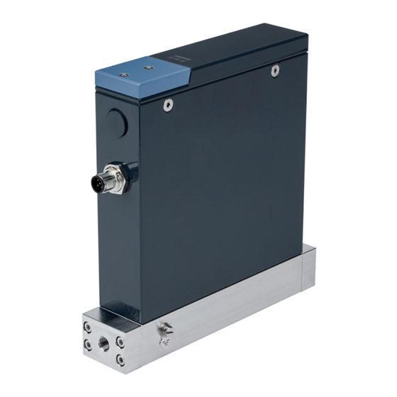
Type 8756 Description descripTiOn 3. Possible fluid connections: • G-threaded connections according to DIN ISO228/1 Product variants • NPT-threaded connections according to ASME/ ANSI B 1.20.1 • male vacuum-fitting connections • male compression-fitting connections 4. M4 screw for functional earth connection 5. Base block 6. Product status-indicator. The indicator operates according to Namur NE 107. 7. Status indicator of the connection to the Ethernet port 1 8. Status indicator of the fieldbus communication 9. Status indicator of the connection to the Ethernet port 2 10. M3 screw 11. Cover 12. büS-interface for Bürkert-Communicator software 13. Slot for the memory card Fig. 1: Mass Flow Meter variants 1. -
Page 10: Product Status-Indicator
Type 8756 Description Product status-indicator The product has an indicator to display the product status. If more than one product status exist simultaneously, then the product status with the highest priority is displayed. Tab. 1: Description of the product status-indicator indicator colour code description meaning according to for a plc NE 107 Failure, error or fault Due to a malfunction of the product or its periphery, the measured values are not valid. Orange Function check Work is done on the product. The output signal is temporarily invalid. Yellow Out of specification The ambient conditions or process conditions for the product are outside the specified ranges. Product internal diagnostics point to problems in the product or with the process properties. → Blue Maintenance required Do the required maintenance operation. The product continues to measure. Green Diagnostic active No event has been generated. Status changes are shown in colour. -
Page 11: Memory Card
The product is delivered with a memory card that is inserted in the product. The Type 8920 Bürkert-Communicator is a PC-software and At product start-up, there are two possibilities: enables the following actions, for example: • If product-specific data is stored on the inserted memory card, • Setting the parameters of the product, for example the basic the product adopts the data. At product delivery, the memory settings for the product start-up card contains product-specific data. To get a list of the stored • Running the diagnostics, and read the error memories for data, refer to the Help for the Initiation file that can be down- example loaded from www.burkert.com. • Updating the product software • If the inserted memory card is empty, the product loads its • Adjusting the user-defined calibration curve own data on the memory card. A new memory card is empty. The data on the memory card can be transferred to another product To use the Type 8920 Bürkert-Communicator software, refer to with the same article number. For example, the data can be trans- the chapter that is related to the product variant: ferred from a defective product to a new product. • büS /CANopen variant, refer to chpt. 5.4.1. • Analogue variant, refer to chpt. 5.4.2. 5.4.1 büS /CANopen variant... - Page 12 5-pin M12 female connector connector büS stick with termina- jack tion-resistance switch AC/DC adapter female-connector Fig. 2: USB-büS-interface set with article number 00772426 → Download the latest version of the Type 8920 Bürkert-Com- municator software from www.burkert.com → During installation, the büS stick must not be inserted at the PC. Install the Bürkert-Communicator software on a PC. jack male-connector Obey the installation recommendations given in the USB- büS-interface set. Fig. 3: Electrical connection parts of the USB-büS-interface set with Fig. 3 shows the electrical connection parts that are used from article number 00772426 the USB-büS-interface set.
-
Page 13: Analogue Variant
→ Start the Bürkert-Communicator software. 5.4.2 Analogue variant → Click on in the Bürkert-Communicator software to → Buy the USB-büS-interface set with article number 00772551 establish the communication between the Bürkert-Communi- from Bürkert. cator software and the product. A window opens. → Download the latest version of the Type 8920 Bürkert-Com- → Select büs-stick. municator software from www.burkert.com → Choose the port Bürkert büs stick, click on finish and wait → Install the Bürkert-Communicator software on a PC. During until the product symbol appears in the list of devices. installation, the büS stick must not be inserted at the PC. → In the list of devices, click on the symbol related to the → Assemble the parts of the USB-büS-interface set. Refer to product: the menu structure for the product is displayed. Fig. 4. Fig. 4: Assembled parts of the USB-büS-interface set with article... -
Page 14: Technical Data
Type 8756 Technical data Technical daTa Tab. 2: Operating conditions of the product Ambient temperature 0 °C...+50 °C Conformity Fluid temperature • MFM • –10 °C...+60 °C, only in liquid state The product complies with the EU directives according to the EU Ambient humidity < 95%, non-condensing declaration of conformity (if applicable). IP-Code according to The cables must be connected and the Standards EN 60529 mating connectors must be plugged in and tightened. The applied standards, which verify conformity with the EU direc- • MFM • IP65 , IP67 tives, can be found on the EU type examination certificate and/or the EU declaration of conformity (if applicable). Operating pressure • MFM •... -
Page 15: Fluid Data
Type 8756 Technical data Fluid data Density measurement • Density range • 0...5 kg/l Tab. 4: Fluid data • Measurement accuracy • ±0.02 kg/l Calibration conditions for mass flow rate values • Calibration fluid • Water higher than 1.5 kg/h • Repeat accuracy for mass • ±0.005 kg/l • Temperature of the cali- • 25 °C flow rate values higher than bration fluid 1.5 kg/h • Calibration pressure • 4 bar Temperature measurement Mass flow rate measurement •... -
Page 16: Pressure Loss
Type 8756 Technical data ∆p [bar] 7.5 10 12.5 15 17.5 20 22.5 [kg/h] Nominal flow rate Q [kg/h] Fig. 6: Pressure loss diagram, MFM, for water, in the measurement Fig. 5: Measurement range depending on nominal flow rate range 0...25 kg/h Pressure loss Electrical data A Mass Flow Meter (MFM) has a pressure loss that depends on the 6.7.1 büS /CANopen variant... -
Page 17: Analogue Variant
Type 8756 Technical data • Change-over relay with 1 Communication büS and CANopen. The communication Relay output interface type can be chosen with the Bürk- normally closed contact ert-Communicator software. (break contact) and 1 nor- mally open contact (make 6.7.2 Analogue variant contact). Both contacts are free of potential WARNING • Maximum ratings: 1 A, 30 V, ▶ For UL-certified components, only use limited power circuits 30 VA of "NEC Class 2". Markings Tab. 6: Electrical data of an MFM WARNING Operating voltage 24 V DC ±10 % Maximum power consumption 4 W Risk of injury that is due to escape of the fluid. Digital input You can be injured through contact with the operating fluid, its •... -
Page 18: Calibration Plate
Type 8756 Technical data 6.8.1 Calibration plate 1. Type of the product 2. Supply voltage, direct current Mass Flow Meter 3. Consumption according to UL 61010-1 [typical consumption Flow Direction Id: 00****** Conditions: ambient temperature 23 °C, nominal flow rate 100% QC passed: __ . __ . ____ 4. For UL-certified products, only use limited power circuits of "NEC Class 2". 5. Warning symbol: observe the Operating Instructions delivered with the product. 6. Calibration fluid 1. Product variant 7. Sealing material 2. -
Page 19: Additional Markings
Type 8756 Installation insTallaTiOn 6.8.3 Additional markings Conformity marking Safety instructions risk of injury that is due to pressure in the installation or in the product. ▶ Before working on the installation or product, cut the pres- sure. Vent and drain the pipes. Fig. 9: CE marking risk of injury from electric shocks. ▶ Before working on the installation or product, switch off the power. Make sure that nobody can switch the power on. ▶... -
Page 20: Installation Steps
3. Start-up the product. Refer to chpt. 9 Start-up. DANGER Additional documentation risk of injury that is due to pressure in the installation and in • For more information on büS, read the cabling guide that is the product. available in English and German at www.buerkert.com search ▶ Before working on the installation or product, cut the pres- for "Guide for planning büS networks". sure. Vent and drain the pipes. • For more information on CANopen that is related to the product, refer to the Operating Instructions "CANopen Network configuration" at www.buerkert.com. • Product description file and object description for the related product Type (download from www.burkert.com). • Product-specific help in the Bürkert-Communicator software. • büS-driver for LabVIEW on request. English... - Page 21 Type 8756 Installation → We recommend that you install the product in a horizontal pipe WARNING as shown in Fig. 10 or in a vertical pipe as shown in Fig. 11. risk of injury that is due to leakage. Flow direction ▶ At a low mass flow rate and a high pressure, make sure the installation is tight. The tightness prevents incorrect meas- urements or the leakage of the operating fluid. To make sure the installation is tight, observe the following instructions: ▶ Use pipes with a diameter that is adapted to the fluid con- nection of the product, and with a smooth surface. Risk of product mal- function due to bubble NOTICE collection malfunction that is due to contamination. ▶ If a contaminated operating fluid is used, then install a filter upstream of the product. The filter ensures problem-free functioning of the product. See chpt. 6.5 Fluid data. Cavitation of gas in the liquid and degassing must be avoided.
-
Page 22: G1/8'' Threaded Connections
Type 8756 Installation 7.4.1 G1/8'' threaded connections → Do the fluid connection on the other side of the product in the same way. → Remove the protective cap that closes the threaded connection. 7.4.4 Connections with double-ferrule → Do the fluid connection on one side of the product. fittings → Obey the instructions that are given by the manufacturer of → Do the fluid connection on one side of the product. the fitting used. → Obey the instructions that are given by the manufacturer of → Obey the torques that are given by the manufacturer of the the fitting used. fitting used. → Obey the torques that are given by the manufacturer of the → Do the fluid connection on the other side of the product in the fitting used. same way. → Do the fluid connection on the other side of the product in the 7.4.2 NPT1/8'' threaded connections same way. -
Page 23: Electrical Installation
Type 8756 Electrical installation elecTrical insTallaTiOn WARNING Risk of injury from electromagnetic fields. Safety instructions If the functional earth (FE) is not attached, then the requirements DANGER of the EMC directive are not met. ▶ Connect the housing to the functional earth (FE). Use a green- risk of injury from electric shocks. and-yellow cable that is as short as possible. And the cable ▶ Before working on the installation or the product, switch off cross-section must be at least equal to the cross section of the power. Ensure that nobody can reactivate the power. the power-supply cable. ▶ Observe all applicable accident protection and all applicable safety regulations for electrical equipment. NOTICE WARNING requirements for the proper function of the product. ▶... -
Page 24: With Büs Cables From Bürkert
Type 8756 Electrical installation Tab. 7: Accessories: büS extension cables Tab. 8: Accessories: büS cables and female connectors Item Article number Item Article number büS extension cable with 5-pin M12 con- 772492 büS cable, 50 m 772413 nectors, 0.1 m büS cable, 100 m 772414 büS extension cable with 5-pin M12 con- 772402 Straight 5-pin M12 female connector 772416 nectors, 0.2 m Bent 5-pin M12 female connector 772418 büS extension cable with 5-pin M12 con- 772403 If you use a büS cable from Bürkert, then observe the signals of nectors, 0.5 m the conductors as given in Tab. 9. büS extension cable with 5-pin M12 con- 772404 nectors, 1 m... -
Page 25: With Canopen Cables
Type 8756 Electrical installation Tab. 10: Accessories: female connectors Pin Assignment Item Article number Shielding Straight 5-pin M12 female connector 772416 24 V Bent 5-pin M12 female connector 772418 DGND CAN_H Coding lug requirements for the correct operation of the product. • Use a mating female connector with shield connection. CAN_L M12 thread is internally connected to FE • Observe the specifications for the cable and con- Fig. 12: büS /CANopen MFM:Pin assignment, 5-pin M12 male ductors, that are given by the manufacturer of the connector (A coding) mating female connector. -
Page 26: Wiring The Analogue Variant
Type 8756 Electrical installation → Screw the mating female connector to the 5-pin male con- Pin Assignment nector, to the torque given by the manufacturer of the mating Not connected female connector. 24 V Coding lug → Do the functional earthing of the product. Refer to chpt 8.4. Not connected Wiring the Analogue variant NOTICE Measured value analogue output requirements for the correct operation of the product. M12 thread is internally connected ▶ Use shielded cables. The cable shielding can be either a to FE braid shielding or a foil shielding. Fig. 14: Analogue MFM: Pin assignment, 5-pin M12 male connector (A coding) requirements for the correct operation of the product. -
Page 27: Digital Input
Type 8756 Electrical installation → By default, to trigger the totalizer reset, short-circuit the digital Pin Assignment input with the digital input ground. Digital input, GND 8.3.2 Relay output Digital input + Relay - Reference The 5-pin M12 female connector has a relay output. The contact Coding lug switching of the relay can show one of the following event: Relay - Normally • MFM: A warning message has been generated. For example closed contact if the supply voltage is too high, then a warning message is (Break contact) generated. Relay - Normally M12 thread is internally connected • MFM: A failure message has been generated. For example if a open contact to FE sensor failure is detected, then a failure message is generated. (Make contact) Tab. 11 gives the events that are assigned by default to the relay Fig. 15: Analogue MFM: Pin assignment, 5-pin M12 female connector output of the 5-pin M12 female connector of an MFM. -
Page 28: Connecting The Functional Earth
→ Use a green-and-yellow cable that is as short as possible. DANGER And the cable cross-section must be at least equal to the cross section of the power-supply cable. To avoid personal injury: → With a flat screwdriver of size 6.5 mm, loosen the M4 screw. ▶ Make sure the MFM operating-pressure is not higher than See Fig. 16. the operating pressure value on the product data-sheet. Find the data sheet on our homepage: www.burkert.com WARNING M4 screw risk of injury from improper operation. Fig. 16: Location of the M4 screw for the connection of the functional- Improper operation can lead to injuries and damage to the earth cable product and its environment. → Attach the functional-earth green-and-yellow cable to the M4 ▶... -
Page 29: Start-Up Steps
▶ Before working on the installation or product, cut the pres- 3. Energize the product. sure. Vent and drain the pipes. If product-specific data is stored on the inserted memory risk of injury from electric shocks. card, then the product adopts the data. To get a list of the stored ▶ Before working on the installation or product, switch off the data at product delivery, refer to the Help for the Initiation file that power. Make sure that nobody can switch the power on. can be downloaded from www.burkert.com. ▶ Observe all applicable accident protection and all applicable If the inserted memory card is empty, then the product loads safety regulations for electrical equipment. its own data on the memory card. Possible problems related to Burn hazard and fire hazard that are due to hot surface of the the memory card are given in Tab. 14 on page 36. product. NOTICE ▶ Do not touch the hot surface with bare hands. -
Page 30: Operation Of The Büs /Canopen Variant
Type 8756 Operation WARNING If the operating mode of the fieldbus is büS, then the canopen status is set to Operational and the PDOs are sent risk of injury that is due to improper operation. to büS. Improper operation can lead to injuries and damage to the If the operating mode of the fieldbus is CANopen, then the product and its environment. canopen status is set to pre-op until the CANopen network ▶ The operating personnel must have read and understood the master switches the product to Operational. content of the Operating Instructions. ▶ Observe the safety information and the intended use. 10.2.2 Empty-pipe detection ▶ Only properly trained personnel may operate the installation To detect if the pipe is empty, the product monitors the density and the product. value of the liquid. ▶ Only properly trained personnel may change parameters with If the density value is lower than 0.2 kg/l, then the pipe is empty. the help of the Bürkert-Communicator software. The product status-indicator turns yellow. 10.2 Operation of the büS /CANopen An out-of-specification event is generated. -
Page 31: Increasing The Data Transmission Speed
Type 8756 Operation 10.2.4 Increasing the data transmission To increase the data transmission-speed, click set dia- gnostic mode. The function inhibit time switches to set to speed default values. If the data transmission-speed is increased, then the product The data transmission-speed is increased. provides more cyclic process-data. → To go back to the default data transmission-speed, click set For example, the actual value of the mass flow rate is available to default values. The function inhibit time switches to set once every 100 ms by default. If the data transmission-speed is diagnostic mode. increased, then the actual value of the mass flow rate is available once every 10 ms. 10.3 Operation of the Analogue variant → If the data transmission-speed is active simultaneously on several products in the network, then make sure that the bus 10.3.1 Cut-off load does not exceed 50%. -
Page 32: Maintenance
Type 8756 Maintenance mainTenance DANGER If no heavily contaminated fluids are used and if the product is Risk of injury that is due to escape of the fluid. operated according to the Operating instructions, then the product You can be injured through contact with the operating fluid, its is maintenance-free. reaction products, and vapours. 11.1 Maintenance for operation with You can be injured through inhalation of vapours. heavily contaminated fluids ▶... -
Page 33: Replacing The Memory Card
Type 8756 Maintenance 11.2 Replacing the memory card To replace the memory card on the product, do the following: Inserted memory card → De-energize the product. → With a TX8 screwdriver loosen the screws of the cover. Remove the cover. Fig. 18: Cross-sectional drawing Screws → With a TX8 screwdriver, screw the cover to a torque of 1.2 N·m, that is 0.9 lbf·ft. Cover → Restart the product to write the product data on the new memory card. Possible problems related to the memory card are given in Tab. 14 on page 36. Memory card: Make sure the insertion direction is correct. Fig. 17: Insertion direction of the memory card → Remove the old memory card from its slot. → Pay attention to the insertion direction of the memory card. Fig. 18 shows the final position of the memory card in the product. -
Page 34: Troubleshooting If The Product Status-Indicator Shows A Problem
Type 8756 Maintenance 11.3 Troubleshooting if the product status-indicator shows a problem The product has an indicator to show the product status. The colour and status of the indicator change according to Namur NE 107. If more than one product status exist simultaneously, then the product status with the highest priority is displayed. Tab. 12: Troubleshooting if the product status-indicator shows a problem indicator description What to do? according to NE 107 The product is not energised. Energise the product. Flashing (any Product is selected in the Bürkert-Communicator software. After 10 seconds, the product automatically returns to the pre- colour) vious status. Green The product is energised. Defective sensor. - Page 35 Type 8756 Maintenance indicator description What to do? according to NE 107 Yellow One of the following values is out of specification: Operate the product within the specifications. • the fluid temperature • the product temperature • the supply voltage The sensor or the product can be damaged. The product has detected that the pipe is empty. Vent the pipe. Fill the pipe completely with fluid. The product has detected bubbles in the liquid. Increase the fluid pressure. Do not use a fluid that is saturated with air. Observe the installation procedure. BüS /CANopen variant: Other fieldbus participants use the same Assign an individual node ID to each fieldbus participant. node ID. Blue Memory error. Maintenance is needed – Contact the manufacturer. English...
-
Page 36: Troubleshooting Of Other Problems
Type 8756 Maintenance 11.4 Troubleshooting of other problems Tab. 13: Troubleshooting of other problems problem possible cause What to do? The product sta- The power supply is intermittently dropping. The Use a power supply with sufficient power output. tus-indicator goes out product restarts. periodically The voltage drop in the connection cable is too large. Increase the cross-section of the cable. Reduce the cable length. No mass flow rate The pipes are too large or not yet fully vented. Vent the pipes. Change the pipe diameter. Unstable measured You have not connected the functional earth (FE) To connect the functional earth, use a green-and-yellow cable that value properly. is as short as possible. And the cable cross-section must be at least equal to the cross section of the power-supply cable. Tab. 14: Troubleshooting, memory card problem possible cause... -
Page 37: Accessories /Spare Parts
Incorrect accessories and unsuitable replacement parts can cause injuries and damage to the product and its environment. Cable assemblies can be made on request. ▶ Only use the original accessories and the original spare parts 12.2 Additional software from Bürkert. Tab. 17: Documentation and software 12.1 Electrical accessories Download from büS /CANopen variant: EDS file www.burkert.com Tab. 15: Electrical accessories, BüS /CANopen variant Download from item article number Bürkert-Communicator software www.burkert.com büS cable, 50 m 772413 Download from büS cable, 100 m 772414 büS LabView-driver... -
Page 38: Decommissioning
Type 8756 Decommissioning decOmmissiOning DANGER 13.1 Safety instructions Risk of injury from dangerous fluids. You can be injured through contact with the operating fluid, its DANGER reaction products, and vapours. You can be injured through inhalation of vapours. risk of injury that is due to pressure in the installation and in ▶ Before you disconnect pipes or valves, flush out dangerous the product. fluids, release pressure in the pipes and drain. ▶ Before working on the installation or product, cut the pres- ▶ Observe all applicable accident protection and all applicable sure. Vent and drain the pipes. safety regulations relating to the operating fluid used. -
Page 39: Transport
Type 8756 Transport TranspOrT NOTICE Transport damage. Fluid If the product is not protected in transport, the product can be connections damaged. Fig. 19: Fluid connections, for example threaded connections • Remove cables, connectors, product-external filters and installation → Remove the product. equipment. • Protect the electrical interfaces with protective plugs. • Clean and vent contaminated products. • Close the fluid connections with protective caps. Protective caps ensure protection and sealing. • Pack the product in two suitable zip lock bags, to avoid any contamination during the transport. •... -
Page 40: Storage, Disposal
Type 8756 Storage, disposal sTOrage, dispOsal reTurning The prOducT NOTICE no work or tests will be carried out on the product until a valid contamination declaration has been received. incorrect storage can cause damage to the product. • Close fluid connections with protective caps. • Store the product dry and dust-free in sealed zip lock bags. To return a used product, a returns number is required. - Page 42 www.burkert.com...
Need help?
Do you have a question about the 8756 Series and is the answer not in the manual?
Questions and answers