Table of Contents
Advertisement
Quick Links
Advertisement
Table of Contents

Related Manuals for Burkert 8743


Summary of Contents for Burkert 8743
- Page 1 Type 8743 Mass flow meter / Mass flow controller Operating Instructions...
- Page 2 We reserve the right to make technical changes without notice. © Bürkert Werke GmbH & Co. KG, 2023 Operating Instructions 2304/00_EUen 00572427 / Original EN...
-
Page 3: Table Of Contents
Type 8743 Table of contents TABLE OF CONTENTS 1 About this document.......................... 6 Manufacturer ............................ 6 Used symbols ........................... 6 Terms and abbreviations ........................ 7 2 Safety instructions............................ 8 Intended use ............................. 8 Safety.............................. 8 3 Product description.......................... 11 Product overview.......................... 11 Product identification ........................ 13 3.2.1... - Page 4 Type 8743 Table of contents 6.2.2 Relay output........................ 30 Wire the variant Analogue with a 6-pin terminal strip.............. 31 Wire the variant Industrial Ethernet .................... 32 Connect the functional earth ...................... 33 7 Commissioning ............................ 35 Commissioning procedure ...................... 35 8 Configuration with Bürkert Communicator ..................... 36 Setting tools............................
- Page 5 Type 8743 Table of contents 10.12 Set-point value at 0 %, no mass flow, but a non-zero mass flow rate is measured...... 50 10.13 Set-point value at 0 %, mass flows, and a mass flow rate is measured........ 50 10.14 Set-point value is not reached...................... 50 10.15 Network status indicator ........................
-
Page 6: About This Document
Before starting any work on the product, read and observe the respective sections of the document. Keep the document available for reference and give it to the next user. Contact the Bürkert sales office for any questions. Further information concerning the product at country.burkert.com. Manufacturer Bürkert Fluid Control Systems Christian-Bürkert-Str. -
Page 7: Terms And Abbreviations
Type 8743 About this document Terms and abbreviations The terms and abbreviations are used in this document to refer to following definitions. Device Type 8743 Mass flow meter Mass flow controller Unit for relative pressure... -
Page 8: Safety Instructions
Type 8743 Safety instructions SAFETY INSTRUCTIONS Intended use The device MFM is designed to measure the mass flow rate of clean and dry gases. The device MFC is designed to measure and regulate the mass flow rate of clean and dry gases. - Page 9 Type 8743 Safety instructions Changes and other modifications, spare parts and accessories Changes to the device, incorrect installation or use of non-approved devices or components create hazards that can lead to accidents and injuries. Do not make any changes to the device.
- Page 10 Type 8743 Safety instructions Only start the process in a controlled manner following disruptions. Observe sequence: 1. Apply supply voltage or pneumatic supply. 2. Charge the device with medium. Hot surfaces and fire hazard The surface of the device can become hot with fast-switching actuators or with hot media.
-
Page 11: Product Description
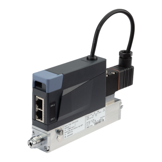
Type 8743 Product description PRODUCT DESCRIPTION The device is used for ultimate precision in the feedback control of medium. This document describes following variant: MFM Analogue MFM Industrial Ethernet MFC Analogue with proportional valve MFC Industrial Ethernet with proportional valve... - Page 12 Type 8743 Product description MFM Industrial Ethernet Fig. 2: Example of a MFM Industrial Ethernet 1 Status indicator (LED) 2 Flow direction 3 Base block 4 Functional earth connection 5 Medium connection 6 Electrical connection 7 3-pin removable terminal strip 8 büS interface...
-
Page 13: Product Identification
10,0 Nl/min N2 IN/OUT 0-5 V Ta=-10°C .. +50°C S/N 1000 W41ME PS=100barg 00****** Fig. 5: Example of type label Type 8743 1 Type 2 Operating voltage 3 Power consumption 4 Note: Observe the operating instructions 5 Medium 1 6 Medium 2... -
Page 14: Calibration Label
Type 8743 Product description 3.2.2 Calibration label Mass Flow Controller Medium 1 Medium 2 P1: 1,00 barg P1: 1,00 barg Mounting: horizontal upright Id: 00****** QC passed: __ . __ . ____ Fig. 6: Description of the calibration label 1 Variant... -
Page 15: Namur Mode
Type 8743 Product description Whether device diagnostics are active or not. Diagnostics are active on the device and cannot be deactiv- ated. If diagnostics are active, then the status indicator shows whether diagnostics events have been generated or not. If several diagnostics events have been generated, then the status indicator shows the diagnostics event with the highest priority. -
Page 16: Network Status Indicator
Type 8743 Product description 3.3.3 Network status indicator Industrial Ethernet variant Fig. 8: Location and description of the LED's of an RJ45 socket 1 Link/Act LED (green) 2 Link LED (yellow) 3.3.4 Communication indicator Industrial Ethernet variant This LED shows the status of the communication between the device and the PLC (Programmable Logical Controller). -
Page 17: Actuator Is A Control Valve
To get a list of the stored data, refer to the file Device Description File that can be downloaded from country.burkert.com. If the inserted memory card is empty, then the device loads its own data on the memory card. A new memory card is empty. -
Page 18: Technical Data
Type 8743 Technical data TECHNICAL DATA Standards and Directives The device complies with the relevant EU harmonisation legislation. In addition, the device also complies with the requirements of the laws of the United Kingdom. The harmonised standards that have been applied for the conformity assessment procedure are listed in the current version of the EU Declaration of Conformity/UK Declaration of Conformity. -
Page 19: Quality Of The Medium
Type 8743 Technical data Turn-down ratio 1:20 (Q < 0,025 l /min) 1:50 (Q ≥ 0,025 l /min) others on request Repeatability ±0.1% of the full scale Measurement accuracy, after ± 0.8% of the measured value 30 minutes warm-up time ± 0.3% of the full scale... -
Page 20: Pressure Loss
Type 8743 Technical data Criteria Quality class Value Maximum dew point under pressure 3 °C Maximum oil concentration 0.01 mg/m Tab. 3: Quality criteria of the medium 4.3.2 Pressure loss A mass flow meter has a pressure loss that depends on the following parameters:... -
Page 21: Electrical Data
Type 8743 Technical data Fig. 11: Formula to calculate the pressure loss in an MFM Pressure loss of the medium Pressure loss of air Density of the medium at the standard conditions according to DIN 1343 (P 1013.25 mbar, T = 273.15 K) Density of air at the standard conditions according to DIN 1343 (P = 1013.25 mbar,... - Page 22 Type 8743 Technical data Electrical connections 6-pin terminal strip, pitch 5.08 m D-sub DE-9 plug büS interface D-sub DE-9 plug Digital input to activate level 1 0...0.2 V Digital input to activate level 2 1...4 V or open Digital input to activate level 3 5...28 V...
-
Page 23: Communication
Type 8743 Technical data Electrical connections 6-pin terminal strip, pitch 5.08 m D-sub DE-9 plug büS interface D-sub DE-9 plug Digital input to activate level 1 0...0.2 V Digital input to activate level 2 1...4 V or open Digital input to activate level 3 5...28 V... -
Page 24: Medium Connection
Type 8743 Medium connection MEDIUM CONNECTION Possible medium connections G-internal-threaded connections according to DIN ISO228/1 NPT-internal-threaded connections according to ASME/ ANSI B 1.20.1 flange connection Installation procedure WARNING! Risk of injury that is due to leakage. At a low mass flow rate and a high pressure, make sure that the installation is tight. The tightness prevents incorrect measurements or leakage of the medium. - Page 25 Type 8743 Medium connection Fig. 13: Pipe cut and deburred Remove the protective cap that closes the threaded connection. ferule Fig. 14: Nut and ferrule on the pipe Slide the nut [A] and then the ferrule onto the pipe. Place the seal [C] on the medium connection.
-
Page 26: Npt-Internal-Threaded Connections
Type 8743 Medium connection 5.2.2 NPT-internal-threaded connections The pipe fittings must be adapted to the medium connection of the device. Compression fittings are available as accessories. Refer to Spare parts and accessories [} 52]. Always complete with a seal for each medium connection. - Page 27 Type 8743 Medium connection Tighten the screws to a torque of 2,7...2,9 N·m (1,99...2,14 lbf·ft).
-
Page 28: Electrical Connection
Type 8743 Electrical connection ELECTRICAL CONNECTION Additional documentation Device specific help in the Bürkert Communicator. Wire the variant Analogue with D-sub DE-9 male connector NOTICE! Requirements for the correct operation of the device. Use a power supply unit with sufficient power. -
Page 29: Digital Input
Type 8743 Electrical connection D-sub DE-9 male connector Assignment Digital input GND for the digital input and the power supply +24 V DC Relay: normally closed contact (Break contact) Relay: reference contact Not used Not used Analogue output for the measured value... -
Page 30: Relay Output
Type 8743 Electrical connection Available functions on MFM Reset the totaliser for the active gas. Select which gas is active among 3 gases. Available functions on MFC Start the function autotune. Trigger the remote control of the actuator or trigger the control of the actuator by the device. -
Page 31: Wire The Variant Analogue With A 6-Pin Terminal Strip
Type 8743 Electrical connection The relay switching can show the following events: A warning message has been generated. For example if the supply voltage is too high, then a warning message is generated. A failure message has been generated. For example if a sensor failure is detected, then a failure message is generated. -
Page 32: Wire The Variant Industrial Ethernet
Type 8743 Electrical connection 6-pin terminal strip Assignment +24 V DC Set-point analogue input + Set-point analogue input GND Actual value analogue output + Actual value analogue output GND Tab. 9: Pin assignment of the 6-pin terminal strip Connect the conductors. Tighten the screws at a torque between 0,5...0,6 N·m (0,37...0,44 lbf·ft). -
Page 33: Connect The Functional Earth
Type 8743 Electrical connection Connect the conductors according to the figure. Earth the device. Refer to Connect the functional earth [} 33] Tighten the conductors at a torque between 0.22...0.25 N (0.16...0.18 lbf·ft.) Connecting the Industrial Ethernet The cable shield is connected by the housing of the cable plug. - Page 34 Type 8743 Electrical connection Industrial Ethernet variant Fig. 20: Connection option on Industrial Ethernet variant Use a green-and-yellow cable that is as short as possible. And the cable cross-section must be at least equal to the cross section of the power-supply cable.
-
Page 35: Commissioning
Type 8743 Commissioning COMMISSIONING Commissioning procedure Pressurise the pipes with medium. Flush the pipes with medium at the calibration pressure. Vent the pipes completely. Check if the memory card is inserted. Energise the device. If the device is an MFC, and the medium is not the calibration medium or the pressure conditions have changed, then run the Autotune function. -
Page 36: Configuration With Bürkert Communicator
Analogue variant + Industrial Ethernet variant Use the USB-büS-Interface set with article number 00772551. Download the latest version of the Type 8920 Bürkert Communicator from country.burkert.com. Install the Bürkert Communicator on a PC. During installation, the büS stick must not be inserted at the Assemble the parts of the USB-büS-Interface set. -
Page 37: Setting The Industrial Ethernet Address
Type 8743 Configuration with Bürkert Communicator Choose the port Bürkert USB büS stick, click on Finish and wait until the device symbol appears in the list of devices. In the navigation area, click on the symbol related to the device: The device menu appears. -
Page 38: Change Of Medium
Type 8743 Configuration with Bürkert Communicator Change of medium At delivery the device is calibrated by the manufacturer with Nitrogen and a conversion factor to the me- dium. With the Bürkert Communicator, it is possible to change the medium by using a LUA-Script which can be downloaded at country.burkert.com. -
Page 39: Operation Modes Of An Mfc
Type 8743 Configuration with Bürkert Communicator Set-point value source is kept after a restart, except when the chosen set-point source is Manual set-point value Analyze system. Set-point value source Description Operation mode Analog set-point value source The set-point value is set through Normal operation mode (Closed- the analogue input. -
Page 40: Normal Operation Mode
Type 8743 Configuration with Bürkert Communicator Operating mode Refer to chapter Variant Analogue: Normal operating mode (MFC) Analog set-point value Manual set-point value Choose the source that gives the set-point value [} 42] Stored set-point value Choose the source that gives the set-point value [} 42] Open-loop control mode Choose the source that gives the set-point value [} 42]... -
Page 41: Analogue Variant
Type 8743 Configuration with Bürkert Communicator If the operating conditions have changed, then optimise the closed-loop control parameters. Refer to Optimise the closed-loop control parameters [} 41] To change the operation mode, change the source for the set-point value. Refer to Choose the source that gives the set-point value [} 42]... -
Page 42: Choose The Source That Gives The Set-Point Value
On a Industrial Ethernet variant it is possible to alternatively change the related object. Refer to the related procedure in the product-specific help in the documentation of the initiation files. Download the initiation files and the related documentation at country.burkert.com. The setting of the parameter... -
Page 43: Set-Point Values Without Communication
Type 8743 Configuration with Bürkert Communicator Analyze system: the device operates in the normal operation mode, but according to a predefined chro- nological sequence with set-point values. Use the resulting diagram in combination with the graphical representation of process values to analyse the system with the Bürkert Communicator. -
Page 44: Maintenance
Type 8743 Maintenance MAINTENANCE If the device is operated according to the Operating instructions, then the device is maintenance-free. Inspect and clean the stainless steel mesh-filter The inspection and possibly cleaning of the stainless steel meshfilter must be done at regular intervals. The inspection frequency and cleaning frequency depend on the measured medium. -
Page 45: Replace The Memory Card
Type 8743 Maintenance Replace the memory card De-energise the device. With tweezers slightly push the memory card to the stop in the device and release. The old memory card comes out. Pay attention to the insertion direction of the memory card. -
Page 46: Troubleshooting
Type 8743 Troubleshooting TROUBLESHOOTING 10.1 Status indicator is red Cause Solution The supply voltage is out of the error Operate the device within the specifications. If the status in- range. The device can be damaged. dicator is still red, then send the device back to Bürkert. -
Page 47: Status Indicator Is Yellow
Type 8743 Troubleshooting Cause Solution A calibration procedure is in progress. Wait until the calibration procedure is completed. The Autotune is in progress. Wait until the Autotune is completed. The operation mode of the device is set Refer to Choose the source that gives the set-point value... -
Page 48: Status Indicator Is Off
Type 8743 Troubleshooting 10.5 Status indicator is off Cause Solution The device is not energised. Make sure that the device is correctly wired. Make sure that the voltage supply is 24 V DC. Make sure that the power supply source is working prop- erly. -
Page 49: No Mass Flow Rate
Type 8743 Troubleshooting 10.10 No mass flow rate Cause Solution The pipes are too large or not yet fully Vent the pipes. vented. Change the pipe diameter. Cause Solution The device is not in the normal operation If the device is not running one of the functions described in... -
Page 50: Set-Point Value At 0 %, No Mass Flow, But A Non-Zero Mass Flow Rate Is Measured
Type 8743 Troubleshooting 10.12 Set-point value at 0 %, no mass flow, but a non-zero mass flow rate is measured Cause Solution The installation position of the device is Install the device as recommended in Medium connection incorrect. [} 24] Run the Autotune function to adapt to the operating condi- tions. - Page 51 Type 8743 Troubleshooting LED indicator Meaning Action Link/Act-LED (green) is OFF. No connection to the network. Check the cable. Link-LED (yellow) is ON Connection to the network is es- tablished. Link LED (yellow) is not lit Not connected to network.
-
Page 52: Spare Parts And Accessories
Type 8743 Spare parts and accessories SPARE PARTS AND ACCESSORIES CAUTION! Risk of injury, property damage due to incorrect parts. Incorrect options and unsuitable spare parts can cause injuries to people and damage to the appliance and its surroundings. Only use original options and original spare parts from Bürkert. -
Page 53: Additional Software
Type 8743 Spare parts and accessories Item Article number Stainless steel mesh filter, mesh size 250 µm, for MFC with flow rate 689 851 measurement range > 20...100 Nl/min Tab. 19: Mesh filters 11.4 Additional software Bürkert Communicator Download from country.burkert.com Tab. 20: Documentation and software... -
Page 54: Uninstallation
Type 8743 Uninstallation UNINSTALLATION 12.1 Dismantling Relieve the medium pressure in the installation. Flush the device with a neutral medium (for example nitrogen) Relieve the flushing medium pressure in the installation. De-energise the device. Remove the electrical wiring. Disconnect the medium connections. -
Page 55: Logistic
Type 8743 Logistic LOGISTIC 13.1 Transport NOTICE! Transport damage. If the device is not protected in transport, then the device can be damaged. Remove cables, connectors, external filters and installation equipment. Protect the electrical interfaces with protective plugs. Clean and vent contaminated devices.
Need help?
Do you have a question about the 8743 and is the answer not in the manual?
Questions and answers