Table of Contents
Advertisement
Quick Links
Advertisement
Table of Contents

Related Manuals for Palfinger INTERLIFT CITYFIX 1100


Summary of Contents for Palfinger INTERLIFT CITYFIX 1100
- Page 1 INSTALLATION MANUAL CITYFIX, 1100 lbs. Capacity 01/24...
- Page 2 Copyright © 2023 Palfinger Interlift, LLC. All rights reserved. Information in this document is subject to change without notice. Visit www.palfinger.com for up to date information and notifications. If you received this product with damaged or missing parts, contact INTERLIFT Liftgates at (888)-774-5844 Parts Order/Inquiries liftgateparts@palfinger.com...
-
Page 3: Table Of Contents
CITYFIX 1100 Installation Manual Table of Contents LIFT LOCATION ........................4 LIFT INSTALLATION GUIDELINES ..................4 LIFT MECHANICAL INSTALLATION ..................5 ELECTRICAL INSTALLATION ....................6 INSTALL MAIN CIRCUIT BREAKER ................7 ROUTE AND CONNECT MAIN POWER CABLE ............7 GROUND CONNECTIONS ................... 9 INTERLOCK INSTALLATION .................. -
Page 4: Lift Location
CITYFIX 1100 Installation Manual LIFT LOCATION The installation surface must be flat and level. It is recommended that lift be installed on a 12mm, minimum, high grade plywood sub-floor. However, this additional installation height may not be acceptable in cases where overhead clearance is limited. NOTE: Check for proper travel clearance through doorway. -
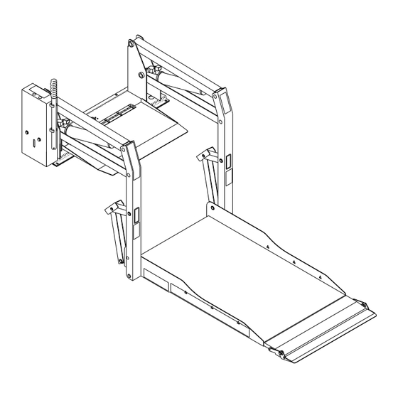
Page 5: Lift Mechanical Installation
CITYFIX 1100 Installation Manual LIFT MECHANICAL INSTALLATION Refer to Diagrams no. 2 and 3. Clamping bars are used to help distribute floor loading and should only be shortened if necessary to clear a subframe member. A subframe member should be used to support forward end of clamping bar. WARNING! Lift weight is approximately 160-170 kgs. -
Page 6: Electrical Installation
CITYFIX 1100 Installation Manual CLAMPING BAR BASEPLATE Diagram No. 3 e. Verify that lift baseplate is as level as possible. Tightening carriage bolts requires special care to prevent the baseplate warping when it is secured to vehicle floor. If baseplate warps, the vertical arms will not be parallel. Corrections can be made by shimming at appropriate locations. -
Page 7: Install Main Circuit Breaker
CITYFIX 1100 Installation Manual BATTERY 4 AWG POWER CABLE: SHORT CABLE, NOT TO EXCEED 12", CONNECTED BETWEEN BATTERY (OR MAIN POWER SOURCE) MAIN CIRCUIT BREAKER 4 AWG POWER CABLE: LONG CABLE CONNECTED BETWEEN MAIN CIRCUIT BREAKER AND POSITIVE TERMINAL OF SOLENOID PUMP SOLENOID BUS BAR... - Page 8 CITYFIX 1100 Installation Manual NOTE: For applications where power cable is to pass through sheet metal, drill a 20mm hole and use a wire clamp. For applications where cable is to pass through plywood, drill a 25mm hole and use black plastic grommet provided. 1.
-
Page 9: Ground Connections
CITYFIX 1100 Installation Manual Diagram No. 6 Diagram No. 7 C. GROUND CONNECTIONS 12VDC powered lifts are chassis grounded and do not require a separate ground cable connection to battery. However, if lift electrical system is connected to chassis with a cable, the cable must be attached in a manner that provides a reliable electrical connection. -
Page 10: Interlock Installation
CITYFIX 1100 Installation Manual D. INTERLOCK INSTALLATION An interlock device can be installed to prevent unsafe operation of the lift. This interlock device consists of a switch mounted near the driver seat that interrupts power to the lift control circuitry. The installer must verify that none of the original equipment circuit breakers, fuses, or solenoids are bypassed, removed, or altered. - Page 11 CITYFIX 1100 Installation Manual Diagram No. 8 Rev. 1.2...
-
Page 12: Limit Switch Adjustment
CITYFIX 1100 Installation Manual E. LIMIT SWITCH ADJUSTMENT For lift limit switch adjustment, refer to Diagram no. 9, and the following procedure. NOTE: To avoid operational “dead-spots”, always adjust DEPLOY CUTOFF SWITCH before RAISE CUTOFF SWITCH. NOTE: When loosening adjustment screws, apply enough pressure to screw to move block instead of screw. - Page 13 CITYFIX 1100 Installation Manual Diagram No. 10 TABLE 2-1: LIMIT SWITCH ADJUSTMENT CHART CORRECTIVE COMPONENT SYMPTOM ADJUSTMENT PROCEDURE ACTION Fold cutoff Lift does not Rotate collar With lift fully folded (handrails actuator fold tightly. counter-clockwise. should be folded tight against vertical arms), rotate actuator so that fold cutoff leg barely trips fold cutoff switch.
-
Page 14: Verify Installation
CITYFIX 1100 Installation Manual VERIFY INSTALLATION Be certain that no vehicle components interfere with operation of CityFix. • The CityFix is designed to handle 500kgs. The vehicle structure must be capable of • supporting all loads produced during lift operation, as well as those forces caused by motion of vehicle when it is driven. - Page 15 CITYFIX 1100 Installation Manual Rev. 1.2...
Need help?
Do you have a question about the INTERLIFT CITYFIX 1100 and is the answer not in the manual?
Questions and answers