
Subscribe to Our Youtube Channel
Related Manuals for Palfinger INTERLIFT ILK 18


Summary of Contents for Palfinger INTERLIFT ILK 18
- Page 1 OWNER’S MANUAL ILK 18, 1800 lbs. Capacity ILK 22, 2200 lbs. Capacity ILK 33, 3300 lbs. Capacity ILK 44, 4400 lbs. Capacity ILK 55, 5500 lbs. Capacity ILK 66, 6600 lbs. Capacity 12/23...
- Page 2 Copyright © 2023 Palfinger Interlift, LLC. All rights reserved. Information in this document is subject to change without notice. Visit www.palfinger.com for up to date information and notifications. If you received this product with damaged or missing parts, contact INTERLIFT Liftgates at (888)-774-5844 Parts Order/Inquiries liftgateparts@palfinger.com...
-
Page 3: Table Of Contents
Owner’s Manual ILK 18/22/33/44/55/66 Table of Contents Table of Figures ........................4 Manual Updates ...................... 6 Important Notes ...................... 7 Attention ..................... 7 Important Notes ..................7 General Information ..................8 Safety Information ....................10 Basic Parts in Detail ..................... 12 General View of Liftgate ................ -
Page 4: Table Of Figures
Owner’s Manual ILK 18/22/33/44/55/66 8.3.2 Electrical Schematic ..............37 8.3.3 Connector Overview ..............38 8.3.4 Hydraulic Schematic ..............39 Needed Information for Ordering Spare Parts and Repairs ....... 40 Ordering Spare Parts ................40 Repairs ..................... 40 Warranty ........................ 40 Contact Address .................... - Page 5 Owner’s Manual ILK 18/22/33/44/55/66 Company Information: Company Name: Advisor Name: Vehicle Year Make & Model: Liftgate Information: Liftgate Serial Number: Liftgate Model Number: Date of Purchase: Date of Installation: Thank you for choosing INTERLIFT Liftgates. Rev. 1.5...
-
Page 6: Manual Updates
Owner’s Manual ILK 18/22/33/44/55/66 Manual Updates Revision Description • Changed the logos, from Palfinger to Interlift v1.5 Rev. 1.5... -
Page 7: Important Notes
Owner’s Manual ILK 18/22/33/44/55/66 Important Notes Attention Before starting any operations of the liftgate, please read and understand this OWNER’S MANUAL. Its intention is to act as a guide for the operation personal as well as to give help with preventive maintenance but does not take place of unauthorized usage or repair by unqualified personnel. -
Page 8: General Information
Owner’s Manual ILK 18/22/33/44/55/66 The valves do not prevent overloading of the platform when lowering or tilting down. The electric supply is taken from the vehicle battery. If the vehicle battery is not sufficient, an auxiliary battery kit needs to be installed. The electric control power is secured via a 20 Amp fuse and an on-off switch located inside the cab. - Page 9 Owner’s Manual ILK 18/22/33/44/55/66 3. Always maintain the liftgate and inspect it for damage before usage. If there are signs of improper maintenance, damage to vital parts or slippery platform surface, do not use the liftgate. Do not attempt your own repairs unless you are specifically trained. 4.
-
Page 10: Safety Information
Owner’s Manual ILK 18/22/33/44/55/66 Safety Information This manual follows the Guidelines set forth in “ANSI Z535.4-2007” for alerting you to possible hazards and their potential severity. ! DANGER indicates an imminently hazardous situation which, if not avoided, will result in death or serious injury. - Page 11 Authorized Service Center in your area. 5) Maintain this manual in the vehicles cab at all times. Replacement manuals are available, just call us & order your manuals for FREE or download from www.palfinger.com. Rev. 1.5...
-
Page 12: Basic Parts In Detail
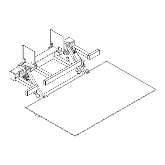
Owner’s Manual ILK 18/22/33/44/55/66 Basic Parts in Detail General View of Liftgate 3 Button Hand control Mount frame Tilt Cylinder Serial Tag Lift Arm Lift Cylinder Control box Rear bumper Circuit Board Center of Gravity of (behind cover) maximum load Platform Hydraulic Power Unit on slide tray... -
Page 13: Circuit Board Connector Cables
Owner’s Manual ILK 18/22/33/44/55/66 Circuit Board Connector Cables Description Part No. PC- board P-200 7193K Cover for control system P-200 7474 Clamp for cover P-201 0169 Wire harness for control box (J30) P-200 7295 Wire harness for hand control (J31) P-200 8921 Wire harness for power pack (J1) P-200 7298... -
Page 14: Control Panel
Owner’s Manual ILK 18/22/33/44/55/66 Control Panel Description Part number CONTROL PANEL OUTER BOX P-2009205 CONTROL BOX LID P-2007476 LABEL P-2007278 CONTACT BLOCK P-2007457 MOMENTARY TURN SWITCH P-2007456 Rev. 1.5... -
Page 15: Maximum Load And Placing Of Load On Platform
Owner’s Manual ILK 18/22/33/44/55/66 Maximum Load and Placing of Load on Platform Every INTERLIFT Liftgate is rated up to a maximum load. The point of maximum load is rated at a defined distance. The center point of maximum load is at 24” (1800 to 3300 lbs) or at 30” (4400 to 6600 lbs) from start of Truck or Trailer Body, as shown in Figure 2. -
Page 16: Figure 4: Load Diagram (Ilk Plus 44 To 66)
Owner’s Manual ILK 18/22/33/44/55/66 Figure 4: Load Diagram (ILK Plus 44 to 66) Rev. 1.5... -
Page 17: Operation Of Liftgate
Owner’s Manual ILK 18/22/33/44/55/66 Operation of Liftgate Turn Control switch to “ON”, the L.E.D.’s will light up inside the cab. All liftgate functions Before use: can be controlled by the 2-switch control box, which is mounted on the curb side of the truck or trailer. -
Page 18: Operation By Hand Held Remote Control
Owner’s Manual ILK 18/22/33/44/55/66 Operation by Hand Held Remote Control 1. LOWERING DOWN: Push button number 3 2. LIFTING UP: Push button number 1 Tilt functions: Push button number 2 while lifting or lowering 1. TILT DOWN: Push button 2 and 3 at the same time 2. -
Page 19: Operation By Foot Control (Optional)
Owner’s Manual ILK 18/22/33/44/55/66 Operation by Foot Control (optional) DOWN: Step on switch 1 and hold – wait between one and three seconds before you step on switch 2. → For auto tilt, stay on the switches till platform starts tilting. Step on switch 2 and hold –... -
Page 20: Application Of The Liftgate For Dock Loading
Owner’s Manual ILK 18/22/33/44/55/66 Application of the Liftgate for Dock Loading → Move platform under the ramp and apply a cantilever drive-over dock plate (Fig. 4). Always chock the wheels using Dock Loading If not possible, there are other ways of loading: •... -
Page 21: Preventive Maintenance And Quick Check
Owner’s Manual ILK 18/22/33/44/55/66 Preventive Maintenance and Quick Check The ILK Plus needs preventive maintenance to perform at its fullest capability. Lubricate and inspect regularly. Also, check that all details are not damaged: Hoses, cables, controls, etc. REPAIR OR REPLACE IMMEDIATELY FAULTY PARTS Maintenance and Care The following inspection and maintenance should be performed at the recommended intervals depending on operation and amount of cycles or at the time when the unit shows any signs of damage or abuse. -
Page 22: Lubrication
Owner’s Manual ILK 18/22/33/44/55/66 Lubrication Properly lubricated, the ILK Plus INTERLIFT Liftgate will ensure longevity. Therefore, lubricate the liftgate at the same time as the truck/trailer. Grease more frequently if the liftgate is heavily used. The liftgate should be greased every 1200 cycles (depending on use – estimated every 3 month). Check the oil level in the tank. -
Page 23: Checking And Changing The Oil
Owner’s Manual ILK 18/22/33/44/55/66 7.2.2 Checking and Changing the Oil Check the quality of hydraulic fluid. If bad, take the following steps to change the oil. To begin, lower gate to ground and tilt platform down, remove lock bolt. Pull the power pack out till you can reach the oil filler cap. Unscrew the oil drainage bolt (bottom of tray) and let the fluid drain out of the reservoir into an approved container. -
Page 24: Decal Placement And Inspection
Owner’s Manual ILK 18/22/33/44/55/66 Decal Placement and Inspection For operator’s safety, all decals appearing in “Decal Kit” must be in a conspicuous place on control side of liftgate to be read by operator. This is typically a combination of decals on the liftgate and truck body. -
Page 25: Figure 7: Decal Placement Guideline
Owner’s Manual ILK 18/22/33/44/55/66 Decal K Decal J Decal C Decal A Decal H Decal F Decal B Aluminum operation plate for foot control 3”x4”, P-1341966 Decal G (on the back of the platform; visible Decal D - in the cab or at from outside when... -
Page 26: Quick Check List
Owner’s Manual ILK 18/22/33/44/55/66 Quick Check List 1. Operate the liftgate throughout its entire operation and check for noise and damage such as bent parts or cracked welds. 2. Inspect all welds and fasteners that attach the mount frame to the truck. All pins and bolts that connect the lift arm to the mount frame and to the platform. -
Page 27: Troubleshooting
Owner’s Manual ILK 18/22/33/44/55/66 Troubleshooting ATTENTION: Please check the following points before looking for faults: Dangerous injuries possible from tools short circuiting main battery connections. Every time you are finished troubleshooting, close the rubber cover on the curbside of the mount frame. - Page 28 Owner’s Manual ILK 18/22/33/44/55/66 2. Check the circuit breaker at the main batteries. Every truck has a circuit breaker on top of the main battery. If you have a studio unit, or a trailer, you will also find an auxiliary battery kit as shown in the pictures below (“Truck Battery” and “Auxiliary Battery”). If circuit breaker reset arm is popped out, push it back in as shown on the decal ATG-BKR next to your breaker or on battery box lid.
-
Page 29: On-Off L.e.d.s Are On But All Functions Are Dead
Owner’s Manual ILK 18/22/33/44/55/66 4. Check the fuse at the power pack and battery. The control board has two 15 Amp fuses and at the battery there should be a 20 Amp fuse. Check all fuse holders for blown fuse(s) and replace each blown fuse with the same amperage. DO NOT use higher amperage fuse. -
Page 30: Continue To Stay On, After Switch Is Turned Off
Owner’s Manual ILK 18/22/33/44/55/66 8.1.3 L.E.D.s continue to stay on, after switch is turned off • Make sure platform is closed and stored vertically. • Adjust the B-15 switch. • B-15 is not working → unplug J-41 (gate operates without sensor but looses auto-tilt). Make sure, the wire B-15 adjustment: strain relief is always... -
Page 31: Possible Cause & Remedy Of Liftgate Malfunction
Owner’s Manual ILK 18/22/33/44/55/66 Possible cause & remedy of liftgate malfunction OPENING Turn on on-off switch in cab Flashes fast light on Is off Platform sensor b15 defective 1. On-off switch defective 1. Fuses e1, e2 on line “2” and “27” at circuit board defective Tilt open tail lift 3. - Page 32 Owner’s Manual ILK 18/22/33/44/55/66 LOWERING Operate auxiliary and down switch or foot switch Platform does Tail lift lowers Platform does not lower not lower 1. Both foot switches not activated 1. Auxiliary switch or down switch 2. Foot switch defective defective 3.
- Page 33 Owner’s Manual ILK 18/22/33/44/55/66 Tilt up to pre-set level Platform does Operate auxiliary Platform does not lift up and up switches not tilt up to or foot switches pre-set position 1. Both foot switches not activated 1. Platform sensor B15 defective 2.
- Page 34 Owner’s Manual ILK 18/22/33/44/55/66 CLOSING Operate auxiliary and tilt up Tail lift closing Platform does not close 1. Aux. switch or tilt up switch defective 2. PC board does not activate J1 #12 And J1 #3 3. Motor solenoid or shift valve S5 not activated 1.
-
Page 35: Electrical And Hydraulic Schematic
Owner’s Manual ILK 18/22/33/44/55/66 Electrical and Hydraulic Schematic 8.3.1 Wiring Diagram - Truck Wires #2 and #4 go to postitive (+) *In-Line Fuse Wires #1 and Gr/Yl go to ground (-) *Resetable Circuit Breaker Main Batteries Ground 2GA. Liftgate Power Cable *In-Line ATC Fuse: 20 Amp. - Page 36 Owner’s Manual ILK 18/22/33/44/55/66 Wires #2 and #4 go to postitive (+) *In-Line Fuse Wires #1 and Gr/Yl go to ground (-) Aux. Batteries Resetable Circuit Breaker Ground 2GA. Liftgate Power Cable 4-Conductor Control Power Cable from Control Board *In-Line ATC Fuse: 20 Amp. Replace with same amperage fuse when necessary. **Resetable Circuit Breaker: 150 Amp Min.
-
Page 37: Electrical Schematic
Owner’s Manual ILK 18/22/33/44/55/66 8.3.2 Electrical Schematic Figure 8: Electrical Schematic Rev. 1.5... -
Page 38: Connector Overview
Owner’s Manual ILK 18/22/33/44/55/66 8.3.3 Connector Overview B15 PLATFORM WARNING FOOT B13 LIFT ARM GROUND for PC BOARD LIGHTS CONTROL (green/yellow and black # 1) CAB CUT OFF SWITCH CONTROL POWER PACK POSITIVE for PC BOARD HAND (black #2 to 2 REMOTE and black # 4 to 27) CYLINDERS... -
Page 39: Hydraulic Schematic
Owner’s Manual ILK 18/22/33/44/55/66 8.3.4 Hydraulic Schematic Functions: S1 and S2 = Release Valve for lowering function S3 and S4 = Release Valve for tilt down function R1 and R2 = Flow Restrictor located inside hose adaptor on lift cylinder R3 and R4 = Flow Restrictor located inside hose adaptor on tilt cylinder S5 = Shift Valve is activated on tilt up and lowering function R5 = Restrictor Valve located in power pack... -
Page 40: Needed Information For Ordering Spare Parts And Repairs
In order to assure quick delivery of spare parts, please always state the following information when making orders: Liftgate model & serial number. Parts manuals are available at www.palfinger.com if necessary. Designation and number of the spare part in accordance with the spare parts list. -
Page 41: Contact Address
Owner’s Manual ILK 18/22/33/44/55/66 Contact Address 15939 Piuma Ave Cerritos, CA 90703 Phone: (562)-924-8218 Fax: (562)-924-8318 E-mail (parts order): liftgateparts@palfinger.com E-mail (technical support): technicalapplications@palfinger.com 572 Whitehead Road Trenton, NJ 08619 Phone: (609)-587-4200 Fax: (609)-587-4201 E-mail (parts order): liftgateparts@palfinger.com E-mail (technical support): technicalapplications@palfinger.com...
Need help?
Do you have a question about the INTERLIFT ILK 18 and is the answer not in the manual?
Questions and answers