Advertisement
Quick Links
Advertisement

Related Manuals for Palfinger ILU


Summary of Contents for Palfinger ILU
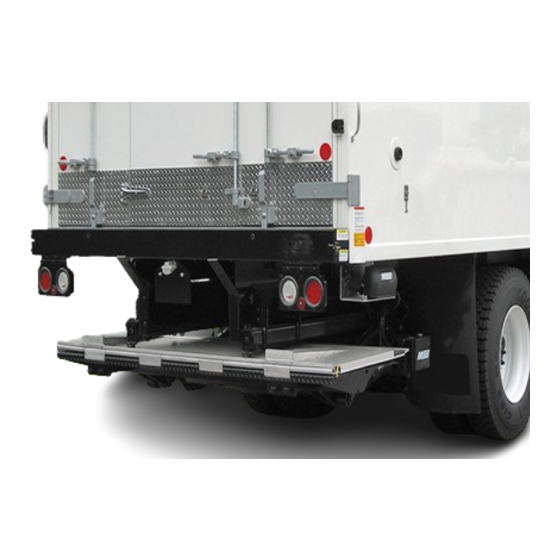
- Page 1 Model ILU Underslider Liftgate Maintenance and Troubleshooting...
- Page 2 ALL MODELS OF PALFINGER LIFTGATES Installation, Operator(Owner) and Parts Manuals,troubleshooting guides, hydraulic and electrical schematics are available for download or viewing on our website at https://www.palfinger.com/en-US/usa/products/lift-gates. Diagrams of decal placement are in the Installation and Operator Manuals. Decals are furnished at no cost to our customers.
- Page 3 Slider Rails Push-Pull Cylinders Tilt Cylinder Tilt, Lift and On/Off switch Lift Cylinders Slide Controls Folding Tilt Platform Cylinder Foot Controls Raise or Lower Warning Lights Platform...
- Page 4 Pins, Bushings and Restrictor Valves Restrictor Valve Number on valve describes the fluid flow (liters per minute) Pin diameter determines lifting capacity...
-
Page 5: Lift Cylinder
Restrictor Solenoid Valve Hose Connection “A” Lift Cylinder Hose connection “A” Solenoid Valve Hose connection “B” Tilt Cylinder Restrictor Restrictor Adjusting head – tilt only... - Page 6 Lift Cylinder Tilt Cylinder...
- Page 7 Power Pack System Components 1. Motor 12 V 2. Plastic Tank 3. Hydraulic Pump 4. Valve plug 5. S5 Shift Valve 6. Pressure Relief Valve 7. Shuttle Valve 8. Restrictor Valve R5 9. Pressure Gauge...
- Page 8 S5 shift valve Ground post Positive post A & B port for hydraulic hoses Pressure gauge connector Motor solenoid with positive post from battery...
- Page 9 Hydraulic Symbols in Schematics Shift valve S5 Motor with Pump Pressure gauge Pressure relief valve Single locking valve Shuttle valve / (Flow divider) Restrictor valve...
- Page 11 S-7 and S-8 Valves To Plug J-42 with Ground Wires...
- Page 12 ILU Electrical Control Overview of Circuit Board, Connectors and Electrical Schematic K plus Circuit Board M Control Circuit Board 2005 to August 2013 August 2013 and newer M Control Circuit Board with L.E.D. Digital Fault Code Display...
- Page 13 New Style Circuit Board – M Control Protective Cover LED flashes green when OK Slots sized for specific plugs LED flashes red when a fault exists Prevent plugs from being LED in lower left corner shows plugged in wrong code for fault...
- Page 14 Circuit Board – M Control Fault Codes Digital Fault Code Display located in lower left corner of M Control Circuit Board...
- Page 15 Two middle Slots Empty...
- Page 16 Circuit Board – K-Plus 2005 to August 2013 Schematic Two middle slots Empty ILU +...
- Page 17 Circuit Board – M Control Schematic...
- Page 18 Basic Flooded Battery Conditions and Testing BEFORE YOU START TROUBLESHOOTING 10-10 TEST CHECK BATTERY VOLTAGE Using a multimeter set on DC Voltage: Place Negative lead on Negative Post on Motor. Place Positive lead on Positive Post on Motor. Using the Lift Switch raise the platform to bed level. Keeping the switch activated.
- Page 19 FLOODED LEAD ACID BATTERY INFORMATION • A flooded lead acid battery reading 12.0V is at less than half charged • Flooded lead acid batteries work best at 90 degrees F. Performance is reduced as temperatures increase or decrease above or below 90 degrees F •...
- Page 20 First Steps Troubleshooting: Low Voltage is a common cause of liftgates not functioning properly. Check all connections making sure they are tight, free of corrosion and properly grounded. 1) Check circuit breaker at batteries and fuses on J1 plug at PC board 2) Unplug unnecessary equipment to eliminate possible problem ...
- Page 21 First Steps Troubleshooting: Continued With ILU gates that have broke down on the road, someone went out and stored liftgate, and now gate is in the shop for repair. Test the gate by jumping large posts on the motor solenoid, gate will dead head and nothing should move.
- Page 22 HYDRAULIC HOSE SET UP CURB SIDE HOSE SET UP ROAD SIDE HOSE SET UP...
- Page 23 B-13 Sensor Located on curb side lift arm. Curb Side Purple epoxy side 12”-14” outwards and wire leads View from Curb Side towards the front of the vehicle. To set the sensor correctly: 1.) Lift unfolded platform up about 12” to 14” above ground. Center slot EMPTY on 2.) Adjust the B-13 sensor in a way that it is level with the M Control Board...
- Page 24 B-15 Sensor Located on underneath platform. B-15 is set correct, when cable restrainer is parallel with platform surface and platform Is horizontal. A reading of 4.0V at the J-41 should be achieved in this position.[ Blue and Brown Wire, see below] NOTE: Voltage reading at Blue wire will increase if platform is tilted Down, voltage will decrease if platform is tilted Up.
- Page 25 FOOT CONTROLS TROUBLESHOOTING When checking voltage on the circuit board, ALWAYS Ground to the circuit board. Circuit Board Ground Points J-3 Plug Pin Functions 5 Pin – UP Orange Wire J-2 Plug, K Plus Board 4 Pin – Hot Grey and Green Wires Green/Yellow or Black #1 6 Pin –...
- Page 26 Make sure King Pin Plate is grounded to side rail. Does Fifth Wheel have a ground strap to the tractor chassis?
-
Page 27: Maintenance Checklist
6. Check for oil leakage around the power pack and Use only original spare parts. If in doubt contact your inside mount tube. Tighten or replace components if PALFINGER Liftgates distributor or call PALFINGER needed. If you perform work on any hydraulic Liftgates directly. - Page 28 Power Cable to Solenoid Coil Test Check for broken power wire in solenoid cable: • Unplug connector at valve. • Set multimeter to read DC voltage. • Put positive lead of multimeter in plug. • Put negative lead of multimeter in other hole of plug.
- Page 29 Solenoid Coil Test If one or both release valves on lift cylinders are not opening up, low voltage may be the cause. A minimum of 9V is necessary to properly energize each of the solenoid coils. If the minimum voltage is present at both coils, the coil may not be generating the magnetism needed to open the solenoid valve.
- Page 30 ILU+ with dual motor...
- Page 31 MBB ILK+ Board connections 2/3 ILU+ Board connections with dual motor WARNING FOOT LIGHTS CONTROL Cab Switch J11 Sensor J41 Platform cable J3 - 2 Permanent Hot - 7 Signal f. Lights - B13 -> Blue, Black, Brown - 4 Control Power - 5 lift - B15 ->...
- Page 32 ILU+ Board connections with dual motor Curb side motor connects to J1 plug on board Road side motor connects to J43 plug on board...
- Page 36 Monday thru Friday Jorge Gallardo – Asst. Tech Support Joe Tabella – Technical Support/Branch Manager, NJ and Warranty Manager 609-587-4200 ext 126 888-774-5844 ext 19 j.tabella@palfinger.com Bob Hennessee – Parts Manager j.gallardo@palfinger.com JD Rodriguez – Parts Manager, West 609-587-4200 ext 128 Coast r.hennessee@palfinger.com...
Need help?
Do you have a question about the ILU and is the answer not in the manual?
Questions and answers