
Related Manuals for Palfinger ILP 25


Summary of Contents for Palfinger ILP 25
- Page 1 INSTALLATION MANUAL & CHECK OFF SHEET ILP 25, 2500 lbs. Capacity ILP 33, 3300 lbs. Capacity 02/19...
- Page 2 Copyright © 2019 Palfinger Liftgates LLC. All rights reserved. Information in this document is subject to change without notice. Visit www.palfinger.com for up to date information and notifications. If you received this product with damaged or missing parts, contact Palfinger Liftgates at (888)-774-5844 15939 Piuma Ave.
-
Page 3: Table Of Contents
ILP 25/33 Installation Manual Table of Contents Manual Updates ........................5 Safety Information ........................6 Important Information ......................7 Tools For Installation ....................... 9 Boxed Items ........................9 General View of Liftgate(s) ....................... 10 ILP General Overview ....................10 Important Dimensions ....................11 Installation Dimensions ...................... - Page 4 ILP 25/33 Installation Manual 13.10 Electrical Schematic (Power Down ) ................57 Hydraulic Schematic (Gravity Down) ..................58 14.1 Hydraulic Schematic (Power Down) ................59 14.2 Hydraulic Fluid ......................60 Decal Placement and Inspection ..................... 61 Lubrication ..........................63 Final Inspection Check List ..................... 64...
-
Page 5: Manual Updates
ILP 25/33 Installation Manual Manual Updates Revision Description Changed product name from PLP to ILP. v1.1 Updated F-Dimensions on Section 8. Added walkramp Section 12.7. v1.2 Revised Sections 13.9, 13-10: Toggle switch wire colors updated. Section 6: Dimension Sheets v1.3... -
Page 6: Safety Information
ILP 25/33 Installation Manual Safety Information This manual follows the Guidelines set forth in “ANSI Z535.4-2007” for alerting you to possible hazards and their potential severity. ! DANGER indicates an imminently hazardous situation which, if not avoided, will result in death or serious injury. -
Page 7: Important Information
Do not paint cylinder shafts or nylon bearings (Use non-chlorinated brake cleaner to remove over spray) Final Check-Off-Sheet at rear of this manual MUST be filled out and sent to Palfinger Liftgates for warranty activation. Refer to Owner’s Manual for Operation and maintenance information. - Page 8 2) Ask your employer or lessor; 3) Call your Palfinger Liftgates Authorized Service Center for assistance. 4) Call Palfinger Liftgates for assistance in the USA at 888-774-5844. You can also contact Palfinger Liftgates by fax (562) 924-8318 or on the internet at www.palfinger.com...
-
Page 9: Tools For Installation
ILP 25/33 Installation Manual Tools For Installation Metric Wrench Set Basic Screwdrivers Assorted Pliers Wire Crimp Pliers Digital Multi-Meter Snap Ring Pliers Hammer SAE & Metric Allen key Set ½” Impact & Sockets SAE & Metric Socket Assorted Drill Floor Jack or Equiv. -
Page 10: General View Of Liftgate(S)
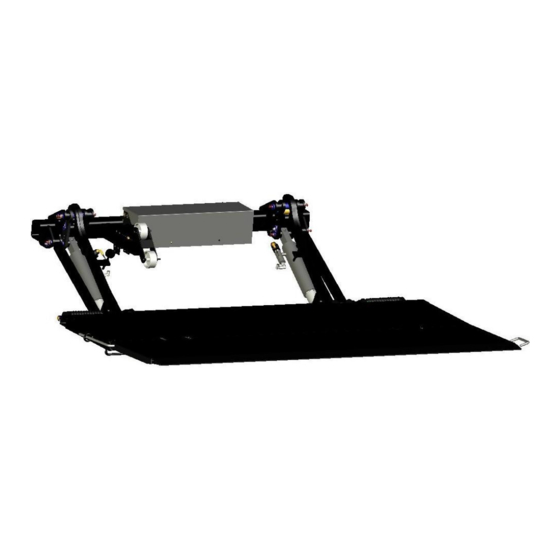
ILP 25/33 Installation Manual General View of Liftgate(s) ILP General Overview Available Options: Lift Capacities: 2500 lbs. or 3300 lbs. Power Down (Electrical) – Power (motor) assisted operation for lowering platform. Power Down (Mechanical) – Spring assisted operation for lowering platform. -
Page 11: Important Dimensions
ILP 25/33 Installation Manual Important Dimensions Minimum Bed Height dimensions are ALWAYS MAXIMUM LOADED TRUCK. Maximum Bed Height dimensions are ALWAYS DRY UNLOADED TRUCK. Installing a gate at or close to minimum bed height normally results in a gate that will NOT open and close from stored position if the minimum floor height is exceeded when truck is loaded. -
Page 12: Installation Dimensions
ILP 25/33 Installation Manual Installation Dimensions Trailer Chassis Dimension Sheet Customer Information Liftgates Information: Quote#/SO#:____________________________________________________ Model: Company:______________________________________________________ Capacity: Phone:_________________________________________________________ Platform Size: Email: _________________________@______________________________ Platform Material: Trailer Information Trailer Specifications: Type of Body Type of Rear Door (check applicable) (check applicable) - Page 13 ILP 25/33 Installation Manual Truck Chassis Dimension Sheet Customer Information Liftgates Information: Quote#/SO#:____________________________________________________ Model Company:______________________________________________________ Capacity Phone:_________________________________________________________ Platform Size Email: _________________________@______________________________ Platform Material Truck Information Truck Specifications: Type of Body Type of Rear Door (check applicable) (check applicable) Manufacturer: Flip-Up (ex.
-
Page 14: Platform Compatibility
ILP 25/33 Installation Manual Platform Compatibility Vehicle bed heights are absolute minimum for the corresponding platform sizes when the vehicle is fully loaded and gassed. 800mm [31.50”] Liftarm Vehicle Platform Sizes 48”x80” 54”x80” Height ... -
Page 15: Chassis And Body Preparation - 800Mm [31.50"] Liftarm
ILP 25/33 Installation Manual 800mm [31.50“] Liftarm Chassis and Body Preparation - -Decrease ground clearance only to clear obstructions (i.e. fuel tanks, cross members, hitches, etc.) WITHOUT EXCEEDING MAXIMUM “F” dimension of 26”. - Minimum bed height is when truck/trailer is loaded to Maximum GVW (Gross Vehicle Weight). -
Page 16: Chassis And Body Preparation - 900Mm [35.40"] Liftarm
ILP 25/33 Installation Manual 900mm [35.40“] Liftarm Chassis and Body Preparation - -Decrease ground clearance only to clear obstructions (i.e. fuel tanks, cross members, hitches, etc.) WITHOUT EXCEEDING MAXIMUM “F” dimension of 28”. - Minimum bed height is when truck/trailer is loaded to Maximum GVW (Gross Vehicle Weight). -
Page 17: Gate Installation
ILP 25/33 Installation Manual Gate Installation 10.1 Sill Cutouts To prevent interference with the platform the vehicles sill could require notching. Options Sill Height Action 4” No sill notching required. 5” If not notched, platform will be offset down approximately 1”-2” from bed extension. -
Page 18: Bed Extension Installation
ILP 25/33 Installation Manual Bed Extension Installation 11.1 Bed Extension (Weld-On) 1. Mark the center of the vehicle body and the bed extension. Clamp the bed extension to the forklift forks, Fig.9. Maintain the bed extension centered and flush to the sill vertically and horizontally. Check for squareness before continuing. - Page 19 ILP 25/33 Installation Manual If using a hoist, make a hole on the edge of a 3” standard channel, Fig.10. Clamp the channels to the bed extension and attached the hoist to the 3” channels. Maintain the bed extension centered and flush to the sill vertically and horizontally.
- Page 20 ILP 25/33 Installation Manual 2. Weld 3/16” x 5” welds on each end on the bed extension. Keep 1” gap clearance on corner post seam line, Fig.11. All other welds shall be 3/16” x 2” centered on each rib, top and bottom of bed extension, Fig.12.
- Page 21 ILP 25/33 Installation Manual Bottom of Bed Extension Sill Welding Areas Extension 2" 3/16" Ribs Fig.12 3/16" 2" Centered on Ribs Bed Extension Bed Extension Ground Ground Fig.13 Rev. 1.4 - 21 -...
-
Page 22: Bed Extension (Bolt-On)
ILP 25/33 Installation Manual 11.2 Bed Extension (Bolt-On) 1. Determine the vehicle width, 96” wide or 102” wide. Pre-drill 19, 5/8” holes on the rear of the sill. Follow the dimensions below. 96.00" Wide 46.50" 46.50" 41.50" 41.50" 34.00" 34.00"... - Page 23 ILP 25/33 Installation Manual 2. Use a forklift, hoist or equivalent to support the bed extension and align the bed extension with the pre-drilled hole pattern on the sill. Verify the bed extension is squared. Secure the bed extension to the sill with the provided 9/16 x1.75”...
-
Page 24: Liftgate Installation (Truck)
ILP 25/33 Installation Manual Liftgate Installation (Truck) 12.1 Liftgate Installation Never work under platform without safety supports High heat from welding can damage components within the heated area. Steps: 1. Hoist Platform: Unfold platform manually and clamp forklift forks, overhead crane or equivalent to platform. - Page 25 ILP 25/33 Installation Manual 1a. Maneuver the liftgate under the vehicle and position both liftarms flush to both the bed extension upstops and the underside of the bed extension. Measure the gap between the bed extension and platform to confirm the gap is within the acceptable range, Fig.16.
- Page 26 ILP 25/33 Installation Manual 1c. Verification: After clamping platform, verify and confirm the following before proceeding: Fig.18. Bed extension and Platform are even. Both liftarms are flush with bottom of bed extension. Both liftarms are flush with bed extension upstops.
- Page 27 ILP 25/33 Installation Manual 2. Set “F” Dimension: “F” Dimension should be determined from Sections 8 and 9 of this manual. Use a floor jack or equivalent to set the mount frame to the required “F” dimension, Fig.19. Use a second jack to level out roll off wheel hitch, if necessary, Fig.20.
- Page 28 ILP 25/33 Installation Manual 3. Bolt-On Mount Plates: Determine the width of the chassis. Orient the mount plates as indicated for that specific chassis width. Assemble the bolt-on mount plate to the mount frame collar with the 5/8-16 hardware. Torque bolts to 180 ft./lbs, Fig. 21.
- Page 29 ILP 25/33 Installation Manual Weld on Mount Plates (Tack): Make sure the mount plate is squared to the mount frame tube vertically and horizontally. Install the mount plate to the chassis and tack weld using three fillet welds, 2” long on each side and on top of the mount plate. Connect the body long rail to the mount plate by adding an extension plate, when necessary, Fig.22.
- Page 30 ILP 25/33 Installation Manual Weld on Mount Plates (Verify): Verify the following: One, F dimension has not changed. Two, bed extension and platform are still squared prior to tack welding the mount plates, Fig.23. Three, gate is operating as intended. Do not power gate hard against bed extension while gate is only tack welded in position.
- Page 31 ILP 25/33 Installation Manual 4. Platform Adjustments (if necessary): Adjustments of the liftgate are not required when the installation procedure has been followed per this manual. In some cases, platform adjustments could be required as not every vehicle is identical and installation variables differ from install to install.
-
Page 32: Adjusting The Platform
ILP 25/33 Installation Manual 12.2 Adjusting the Platform Platform is heavy, use caution while handling. Adjustment of the torsion cam applies to all platforms (steel, aluminum, or steel/alum). Steps: 1. Torsion Cam Installation: To change the amount of platform spring assist, position the gate as shown below with the platform resting on the platform roll-off wheels and shackles contact the ground, Fig.25. - Page 33 ILP 25/33 Installation Manual To add tension to the torsion spring, remove the adjustment cam from its shipping position, Fig.27. Next, install the cam on the inside part of the plate on the engaged position hole. The short leg of the spring should be in contact with the cam, Fig.28.
- Page 34 ILP 25/33 Installation Manual 2. Adjust Sliding Wheel: Loosen the nuts on the wheel bracket assembly. Adjust the wheel in or out along the wheel hitch until the platform is 5° inward. Once the wheel assembly is in set position, secure the wheels by torqueing the six bolts to 16-20 ft/lbs.
- Page 35 Install the 2” side of the angle on the outside of the frame. Weld components to the chassis and the body long rail. Flatbar may not be required if the frame cut out does not have a step. Note: Palfinger Liftgates does not supply cap materials. All material must be supplied by end users.
-
Page 36: Final Steps Of Installation
ILP 25/33 Installation Manual 12.3 Final Steps of Installation 1. Battery Connect: Connect battery cable to batteries, aux batteries to power the liftgate. Refer to electrical installation on Section 13. 2. Cycle Gate: Cycle gate several times to assure proper alignment. -
Page 37: Sub-Frame Installation (Optional)
ILP 25/33 Installation Manual 12.4 Sub-frame Installation (Optional) Trailer installations require a sub-frame to be installed prior to installing the liftgate. Never work under platform without safety supports. Steps: 1. Sub-Frame: Position the sub-frame channels up against the trailers crossmembers in the orientation shown below. -
Page 38: Dock Bumper Installation - Weld-On (Optional)
ILP 25/33 Installation Manual 12.5 Dock Bumper Installation - Weld-On (Optional) Dock Bumper Strut Brace 1pc Curb Side 1pc Street Side Support Channel Dock Bumper 2 pcs 1pc Curb Side 1pc Street Side Steps: 1. Dock Bumpers: Clamp dock bumpers to the bed extension as shown, Fig.32. Check for squareness.Tack weld the dock bumper. -
Page 39: Dock Bumper Installation - Bolt On (Optional)
ILP 25/33 Installation Manual 12.6 Dock Bumper Installation - Bolt On (Optional) Dock Bumper 1pc Curb Side 1pc Street Side Support Channel 2 pcs Dock Bumper Strut Brace 1pc Curb Side 1pc Street Side Washer Clamp Washer 9/16 8 pcs... - Page 40 ILP 25/33 Installation Manual 2. Dock Bumper Support: Each strut brace has a marking for easy identification, the curb side strut has a “C” and the drive side strut has a “D”, Fig.36. Join the support channel to the strut using a set of bolts, clamp washers and flange nuts, Fig.37.
-
Page 41: Walkramp Cradle Installation (Optional)
ILP 25/33 Installation Manual 12.7 Walkramp Cradle Installation (Optional) Hex Head Cap Screw 1/2"-13x1.5" Walk Ramp Upstops 1/2"-13 Nylock 1/2" Washer Walk Ramp Cradle Walk Ramp Extension Walk Ramp Caps Extensions Walk ramp installations apply to the vehicle bed heights and platform sizes below, based on 4”... - Page 42 ILP 25/33 Installation Manual Steps: 1. Walk Ramp: Measure the walk ramp width. The walk ramp cradle has adjustable Slide Guards and Slide Pads to accommodate different widths of walk ramps. Adjust the slide guard and pad by removing the nut and sliding the guard/pad on both side of the cradle to the next available slot.
- Page 43 ILP 25/33 Installation Manual 2. Cradle Position: Position cradle in the orientation shown below with the retainer hook pointing out. Slide the walk ramp cradle assembly between the two bed extension ribs and weld 100%. 4" Sill highly recommended for walk ramp application, especially on lower range of loaded (laden) dimension.
- Page 44 ILP 25/33 Installation Manual 3. Upstops: Position the two upstops 7-3/4” from each side of the walk ramp cradle. Position the upstops up against the back side of the bed extension and weld 100%. IMPORTANT! If the walk ramp cradle has been mounted lower, the upstops need to be lowered equally.
- Page 45 NOTE: The Walkramp Extensions are required to be installed. On vehicles where dock bumpers have not been installed, custom dock bumper structures will need to be installed to Walkramp mount the Walk Ramp Extensions. Palfinger Liftgates does not Extension supply material for these custom dock bumper structures. Caps...
-
Page 46: Electrical Installation
Electrical Installation Any deviation from Palfinger Liftgates’s recommended power setup will void warranty and product liability unless you have a written confirmation by Palfinger Liftgates that allows you to do specific changes. It is the liftgate installer or incomplete vehicle builder responsibility to be certain all chassis ground systems are adequate for the job. -
Page 47: Electrical Wiring - Batteries - Truck/Trailer
ILP 25/33 Installation Manual Electrical Wiring – Batteries – Truck/Trailer 13.1 *Resettable Circuit Breaker: 150 Amp Min. Replace with same amperage breaker when necessary. Ground: For optimal grounding, ground all batteries and power units to the body side rails of the vehicle. -
Page 48: Cable Routing
ILP 25/33 Installation Manual 13.2 Cable Routing 1. The use of wire loom is highly recommended to protect and facilitate cable routing. Wire loom not supplied. 2. Route all cables along the wooden spacer and through the outside of the U-bolts or on the inside part of the channel. -
Page 49: Wire Crimping
ILP 25/33 Installation Manual 13.4 Wire Crimping All grounding surfaces MUST be cleaned, prepped, and sealed per this manual. “Cut to size” cables MUST be properly crimped and sealed as factory supplied. All connections MUST be dressed with dielectric grease or equivalent sealer Battery Cable Crimping 1. -
Page 50: Toggle Switch Installation
ILP 25/33 Installation Manual 13.6 Toggle Switch Installation The Toggle Switch is weatherproof from factory, do no substitute or tamper with the switch. Determine location for fixed toggle switch on corner post in a way that the operator can view the platform and surrounding areas while operating the liftgate. - Page 51 ILP 25/33 Installation Manual Stake Bed Vehicles 1. Mount Switch: Mount toggle switch to dock bumper strut using two #10x1-1/2” self-tapping screws. Dock Bumper Strut Dock Bumper 2. Route Wire: Route the toggle switch harness along the vehicle body down to the pump and motor.
-
Page 52: Liftgate Shut-Off Switch
ILP 25/33 Installation Manual 13.7 Liftgate Shut-Off Switch Liftgate Cab ON/OFF Switch MUST be installed and in clear view of driver. Steps: 1. Mounting Switch: Truck Application: Install the liftgates shut off switch on the vehicles dashboard in clear view of the driver and within reach from the ground, Fig.43. - Page 53 ILP 25/33 Installation Manual Routing Switch Harnesses to Pump and Motor 1. Route each harness to the hydraulic power unit enclosure and secure harnesses with the supplied cable ties. Keep harnesses away from sharp corners and moving parts. 2. Feed the harnesses through the cable entry slots on the enclosure as shown, Fig.45.
-
Page 54: 2-Button Hand Held Remote Control (Optional)
ILP 25/33 Installation Manual 13.8 2-Button Hand Held Remote Control (Optional) 2-Button Hand Held Remote Mounting Screws Hand Held Remote Holster 1. Mount the holster approximately 40”- 48” from the floor, or determine the best location as preferred by end user, Fig.46. - Page 55 ILP 25/33 Installation Manual 4. Use a plug and socket when the vehicle is a refrigerated body. Remove the set screw to access the wire terminals. Never store remote inside refrigerated vehicles, control will be damaged. Set Screw Plug Plug to Control Wiring Table...
-
Page 56: Electrical Schematic (Gravity Down)
ILP 25/33 Installation Manual 13.9 Electrical Schematic (Gravity Down) Rev. 1.4 - 56 -... -
Page 57: Electrical Schematic (Power Down )
ILP 25/33 Installation Manual 13.10 Electrical Schematic (Power Down ) Rev. 1.4 - 57 -... -
Page 58: Hydraulic Schematic (Gravity Down)
ILP 25/33 Installation Manual Hydraulic Schematic (Gravity Down) Insure that all hydraulic hoses are secured and away from heat sources, sharp corners/edges, and abrasion from moving components during the operation of the liftgate and vehicle. S1 & S2 - Release Valve for Lowering R1 &... -
Page 59: Hydraulic Schematic (Power Down)
ILP 25/33 Installation Manual 14.1 Hydraulic Schematic (Power Down) S1 & S2 - Release Valve for Lowering R1 & R2 - Flow Restrictor for limiting lower speed. S5 - Shift Valve is activated upon LOWER function only. Pilot to close check valve is NOT used on Power Down. -
Page 60: Hydraulic Fluid
ILP 25/33 Installation Manual 14.2 Hydraulic Fluid All ILP liftgates are equipped with Hydrex MV Arctic 15 hydraulic fluid from factory. Hydraulic Fluid Installed From Factory Property HYDREX MV ARCTIC 15 Start Up Temperature <50°C / -58°F Operating Temperature -45°C to +23°C / -49°F to 73°F Pour Point -57°C / -71°F... -
Page 61: Decal Placement And Inspection
Make sure to place the maximum capacity decal (D) on driver and curb side of the vehicle. Important: Never remove or paint over any decal. If any decals below require replacement contact Palfinger Liftgates for replacements. Decal Kit Decal Qty. - Page 62 ILP 25/33 Installation Manual Decal - A Decal - B Decal - C Decal - E Decal - F Decal - D Decal – I Decal - G Decal - H Decal – J Driver Side Curb Side Rev. 1.4...
-
Page 63: Lubrication
ILP 25/33 Installation Manual Lubrication 1. Lower the platform to the ground. 2. Remove red protector caps from each component. Lubricate, grease, and oil per diagram below. 3. Cycle platform up and down several times. Lubricate and grease all points again. -
Page 64: Final Inspection Check List
Installation is NOT complete and all WARRANTIES are VOID if you have not checked and verified all items listed on this inspection sheet. Inspection sheet is to be filled out at the facility where liftgate was installed and MUST be sent to Palfinger Liftgates for warranty activation. Structural Inspection ... - Page 65 ILP 25/33 Installation Manual Rev. 1.4 - 65 -...
Need help?
Do you have a question about the ILP 25 and is the answer not in the manual?
Questions and answers