
Related Manuals for Palfinger INTERLIFT ILM+ 16


Summary of Contents for Palfinger INTERLIFT ILM+ 16
- Page 1 OWNER’S MANUAL ILM+ 16, 1600 lbs. Capacity ILM+ 20, 2000 lbs. Capacity ILM+ 25, 2500 lbs. Capacity ILM+ 30, 3000 lbs. Capacity 12/23...
- Page 2 Copyright © 2023 Palfinger Interlift, LLC. All rights reserved. Information in this document is subject to change without notice. Visit www.palfinger.com for up to date information and notifications. If you received this product with damaged or missing parts, contact INTERLIFT Liftgates at (888)-774-5844 Parts Order/Inquiries liftgateparts@palfinger.com...
- Page 3 You can call the customer service department Monday to Friday 7 am to 5 pm Pacific Time or reach INTERLIFT Liftgates 24 hours a day, 7 days a week through the internet home page www.palfinger.com or voice message system. Providing quality, value and service to the customers is what our business is all about.
-
Page 4: Table Of Contents
Owner‘s Manual ILM+ 16/20/25/30 Table of Contents Manual Updates ........................5 Safety Information ........................6 Important Information ....................... 7 Important notes ......................7 General Information ........................10 Before Operation ......................10 Liftgate Function and Usage Information ............... 10 Improper Usage ......................11 General View of Liftgate ...................... -
Page 5: Manual Updates
Owner‘s Manual ILM+ 16/20/25/30 Manual Updates Revision Description v1.7 Updated Section 7.1-7.4. Revised hydraulic and electrical schematics Updated line art v1.8 Changed the logos, from Palfinger to Interlift Rev. 1.8... -
Page 6: Safety Information
Owner’s Manual ILM+ 16/20/25/30 Safety Information This manual follows the Guidelines set forth in “ANSI Z535.4-2007” for alerting you to possible hazards and their potential severity. This is the safety alert symbol. It is used to alert you to potential personal injury hazards. Obey all safety messages that follow this symbol to avoid possible injury or death. -
Page 7: Important Information
Owner‘s Manual ILM+ 16/20/25/30 Important Information Before Getting Started “READ FIRST” Before starting any operations of the liftgate, please read and understand this Owner’s Manual. The intention of this manual is to provide the user a guide for the operation as well as preventive mainte- nance. - Page 8 Owner‘s Manual ILM+ 16/20/25/30 The ILM plus series liftgate is a 100% level-ride, rail style vertical lift liftgate. • Rail style liftgates have two rails mounted to the rear of your vehicle, either by welding or bolting. These rails support a platform which raises and lowers cargo. Lifting actions are carried out by a hydraulic cyl- inder which is equipped with a solenoid operated valve located at the port of the cylinder and prevents the platform from lowering accidentally unless the operator is activating the controls.
- Page 9 4) Call INTERLIFT Liftgates for assistance in the USA at 888-774-5844. You can also contact INTERLIFT Lift- gates by fax (562) 924-8318 or on the internet- www.palfinger.com For technical support, contact INTERLIFT Liftgates or an authorized INTERLIFT service center. www.palfinger.com Replacement manuals are available at no charge by contacting Customer service at 888-774-5844 Rev.
-
Page 10: General Information
Owner‘s Manual ILM+ 16/20/2530 General Information Before Operation REMEMBER: It is the fleet manager’s responsibility to educate the operator on the liftgate and its intended use. The opera- tor’s attention should be drawn to the permitted load limits and an understanding of the operation to ensure the safety throughout the operation. -
Page 11: Improper Usage
Owner‘s Manual ILM+ 16/20/2530 Improper Usage Some examples of improper use of the liftgate may include, but are not limited to: • Using the liftgate as an elevating work platform • Using the liftgate to push, pull, or low loads or other objects. •... -
Page 12: General View Of Liftgate
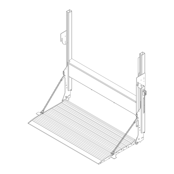
Owner‘s Manual ILM+ 16/20/25/30 General View of Liftgate Rail Platform Rail Storage Latch Runners Platform Storage Safety Latch Storage Latch Side Chain Operating Controls Lift Cylinder (Inside) Hydraulic Power Unit (Inside) Power Open/Close Cylinder (if applicable) Load Center of Gracity Rev. -
Page 13: Maximum Load And Placing Of Load On Platform
Owner‘s Manual ILM+ 16/20/25/30 Maximum Load and Placing of Load on Platform Every Palifinger Liftgate is rated up to a maximum load. The point of maximum load is rated at a defined distance. The center point of maximum load is 24” from the front of the platform. 24"... -
Page 14: Loading And Unloading
Owner‘s Manual ILM+ 16/20/25/30 Loading and Unloading When backing up vehicle to loading dock DO NOT hit the dock. Have a second person outside the truck directing you. Hitting the dock may cause hidden damage to liftgate components. Be sure to inspect the liftgate thoroughly for damage. Make sure to operate liftgate on a level surface. -
Page 15: Liftgate Operation - Manual Close
Owner‘s Manual ILM+ 16/20/25/30 Liftgate Operation – Manual Close Steps: 1. Turn Power Switch On (If applicable): To activate power to the liftgate, turn the cab shutoff switch, Fig.2. Fig. 2 ON/OFF Switch Rocker Switch Location for Trucks 2. Clear the platform sliding path by moving the storage safety latch manually. Hold the safetly latch down manually with one hand and press the Down button on the control with the other hand until the platform locking ears clear the safety latch, Fig. - Page 16 Owner‘s Manual ILM+ 16/20/25/30 4. Center the load 24“ from the front of the platform outward, Fig. 6. Use the Up button to raise the platform to bed level and the Down button to lower the platform down to ground level. Fig.
-
Page 17: Liftgate Operation - Power Close
Owner‘s Manual ILM+ 16/20/25/30 Liftgate Operation – Power Close Steps: 1. Turn Power Switch On (If applicable): To activate power to the liftgate, turn the cab shutoff switch, Fig.8. Fig. 8 ON/OFF Switch Rocker Switch Location for Trucks 2. Clear the platform sliding path by moving the storage safety latch manually. Hold the safetly latch down manually with one hand and press the Down button on the control with the other hand until the platform locking ears clear the storage safety latch, Fig. - Page 18 Owner‘s Manual ILM+ 16/20/25/30 4. Center the load 24“ from the front of the platform outward, Fig. 12. Use the Up button to raise the platform to bed level and the Down button to lower the platform down to ground. Fig.
-
Page 19: Pad Lock (Optional)
Owner‘s Manual ILM+ 16/20/25/30 Pad Lock (Optional) The safety storage latch has an optional hole for the use a pad lock to prevent any unauthorized usage of the liftage. Make sure the the liftgate platform is stored away properly and the safety storage latch is engaged prior to applying the pad lock. -
Page 20: Cart Stops (Optional)
Owner‘s Manual ILM+ 16/20/25/30 Cart Stops (Optional) Aluminum Platform Cart Stops 1. Push the cart stop latch out toward the curb side, Fig. 14. The cart stop will spring open automatically once the latch has been moved from its original position, Fig. 15. 2. - Page 21 Owner‘s Manual ILM+ 16/20/25/30 Steel Platform Cart Stops 1. Each cart stop is equipped with a retaining latch. Push each latch inward to open the cart stop, Fig. 17. The cart stop will automatically spring open once the latch has been pushed, Fig. 18. 2.
-
Page 22: Preventative Maintenance And Quick Check
Owner‘s Manual ILM+ 16/20/25/30 Preventative Maintenance and Quick Check The ILM needs preventive maintenance in order to achieve maximum performance. Lubricate and inspect regularly. Also, check that there are no damaged components such as hoses, cables, controls, etc. Quick Check List Operate the liftgate throughout its entire operation and check for noise and damage such as bent parts, scratches, or cracked welds. -
Page 23: Maintenance And Care
Owner‘s Manual ILM+ 16/20/25/30 IMMEDIATELY REPAIR OR REPLACE FAULTY PARTS Maintenance and Care The following “inspection and maintenance” should be performed at the recommended intervals depending on operation and amount of cycles or at the time when the unit shows any signs of damage or abuse. Remember that the secret to a long life of your INTERLIFT Liftgate is to maintain it through preventive care. -
Page 24: Lubrication
Owner‘s Manual ILM+ 16/20/25/30 Lubrication When kept properly lubricated, the INTERLIFT ILM liftgate will ensure long lasting usage. Therefore, the lift- gate should be lubricated once every 3-months. Average ILM plus use is considered 15 cycles per day or 1200 cycles/3-months. Lubricate more frequently if the lift gate is heavily used or whenever the pivot points appear to be dry. - Page 25 Owner‘s Manual ILM+ 16/20/25/30 Lubrication Locations: All bearing points must be lubricated in accordance with the maintenance schedule. Oil: - Columns Hydraulic Oil: - Resevoir 1 Zerks: - 1 Platform 2 Zerks: - 1 Platform - 1 Cylinder Grease fitting, 2 for deck, 2 for power closing. Hydraulic oil level in the power pack tank 2”...
-
Page 26: Checking And Changing The Oil
Owner‘s Manual ILM+ 16/20/25/30 Checking and Changing the Oil Step 1: To begin, lower the platform to the ground. Step 2: Remove the four screws on the cover. Cover Screws Step 3: Check Oil quality. If bad, follow next steps. Step 4: Force the lift cylinder all the way in to fill up the Oil Reservoir with the oil left over in the cylinder. - Page 27 Owner‘s Manual ILM+ 16/20/25/30 Step 6: Push up-button to start the pump and make sure to catch all the used oil in the container. Fill up the Oil Reservoir with approved oil (approximately up to a level which is about 1” below its Step 7: top (2.2 Liter or 0.58 Gallons), Fig.
-
Page 28: Decal Placement And Inspection
Owner‘s Manual ILM+ 16/20/25/30 Decal Placement and inspection For operator’s safety, all decals appearing in “Decal Kit” must be placed visibly on control side of liftgate to be read by operator. This is typically a combination of decals on the liftgate and vehicle body. - Page 29 Owner‘s Manual ILM+ 16/20/25/30 Decal - C Decal – B Decal– BB Decal – A Decal– AA Decal - F Decal - G Decal - E Decal - I Decal - K Decal - D Decal - H Decal - J Decal - N Decal - M Decal - L...
-
Page 30: Troubleshooting
Owner‘s Manual ILM+ 16/20/25/30 Troubleshooting Dangerous injuries are possible from objects such as tools short circuiting main battery connections. Be sure that you are working in a safe environment. Change oil after working on hydraulic unit (removal of valves, opening of cylinder etc). There is a possibility of injury if somebody other than an authorized technician works on the electrical system. - Page 31 Owner‘s Manual ILM+ 16/20/25/30 3. Are the vehicle batteries charged? Check batteries and the truck/trailer charging system. Start truck and run engine in fast idle for charging the batteries. If the liftgate starts working, recharge and load test batteries. Measure battery voltages: Flooded Batteries: 12.6V, AMG Batteries = 12.8V.
-
Page 32: Wiring Diagram (Main Battery Wiring)
Owner‘s Manual ILM+ 16/20/25/30 Wiring Diagram (Main battery wiring) *Resettable Circuit Breaker Single Pole Socket *Resettable *Resettable Circuit Auxiliary Circuit Breaker Batteries Ground Breaker Truck Batteries Ground 4GA. Liftgate 4GA. Liftgate Power Cable (+) Power Cable (+) Battery Wiring - Truck Battery Wiring - Single Pole - Trailer *Resettable Circuit... -
Page 33: Cross Test On Single Pole Plug Charge System
Owner‘s Manual ILM+ 16/20/25/30 Cross Test on Single Pole Plug Charge System Testing of full system using a battery load tester. Start with testing each individual battery on both tractor and trailer before proceeding to check the system: A. 12V lead from tractor coil cord B. -
Page 34: Wiring Diagram (Manual Closing)
Owner‘s Manual ILM+ 16/20/25/30 Wiring Diagram (Manual Closing) Rev. 1.8... -
Page 35: Wiring Diagram (Power Down )
Owner‘s Manual ILM+ 16/20/25/30 Wiring Diagram (Power down ) Rev. 1.8... -
Page 36: Hydraulic Schematic (Manual Closing)
Owner‘s Manual ILM+ 16/20/25/30 Hydraulic Schematic (Manual Closing) Cylinder Valve Body Lift Cylinder Cap Port Port Pump Unit Port Flow Control Press-Comp 1.0 gpm Shuttle Valve Pump Relief Valve 2900 psi Filter Reservoir Tank ILM Wiring Schematic - Manual Closing 15939 Piuma Ave. -
Page 37: Hydraulic Schematic (Power Closing)
Owner‘s Manual ILM+ 16/20/25/30 Hydraulic Schematic (Power Closing) Cylinder Valve Body Lift Cylinder Port Flow Control Fixed #035 Port Pump Unit Port Flow Control Press-Comp 1.0 gpm Shuttle Valve Pump Relief Valve 2900 psi Filter Reservoir Tank ILM Wiring Schematic - Power Closing 15939 Piuma Ave. -
Page 38: Spare/Replacement Parts And Repairs
Owner‘s Manual ILM+ 16/20/25/30 Spare/Replacement Parts and Repairs Ordering Spare/Replacement Parts 10.1 In order to assure quick delivery of replacement parts, always state the following information when making orders: Liftgate model & serial number. Designation and number of the spare part in accordance with the spare parts list. Designation and number marked on the individual component (if available). -
Page 39: Contact Address
Owner‘s Manual ILM+ 16/20/25/30 Contact Address 15939 Piuma Ave Cerritos, CA 90703 Phone: (562)-924-8218 Fax: (562)-924-8318 E-mail (parts order): liftgateparts@palfinger.com E-mail (technical support): technicalapplications@palfinger.com 572 Whitehead Road Trenton, NJ 08619 Phone: (609)-587-4200 Fax: (609)-587-4201 E-mail (parts order): liftgateparts@palfinger.com E-mail (technical support): technicalapplications@palfinger.com...
Need help?
Do you have a question about the INTERLIFT ILM+ 16 and is the answer not in the manual?
Questions and answers