Table of Contents
Advertisement
Quick Links
Advertisement
Table of Contents

Related Manuals for Palfinger INTERLIFT ILSL 30


Summary of Contents for Palfinger INTERLIFT ILSL 30
- Page 1 OWNER’S MANUAL ILSL 30, 3000 lbs. Capacity ILSL 40, 4000 lbs. Capacity 01/24...
- Page 2 Copyright © 2023 Palfinger Interlift, LLC. All rights reserved. Information in this document is subject to change without notice. Visit www.palfinger.com for up to date information and notifications. If you received this product with damaged or missing parts, contact INTERLIFT Liftgates at (888)-774-5844 Parts Order/Inquiries liftgateparts@palfinger.com...
-
Page 3: Table Of Contents
Owner‘s Manual ILSL 30/40 Table of Contents Manual Updates ........................5 Important Notes ........................6 Attention ........................6 Important Notes ......................6 General Information ...................... 7 Safety Information ........................9 General View of Liftgate ......................11 Maximum Load and Placing of Load on Platform ..............12 Operation of Liftgate ........................ - Page 4 Owner‘s Manual ILSL 30/40 Lower Down ........................40 Lift Up Function ......................40 Slide In Function ......................40 Needed Information for Ordering Spare Parts and Repairs ........... 41 12.1 Ordering Spare Parts ....................41 12.2 Repairs ......................... 41 Warranty ............................ 41 Contact Address ........................
-
Page 5: Manual Updates
Owner‘s Manual ILSL 30/40 Manual Updates Revision Description • Changed the logos, from Palfinger to Interlift v1.3 Rev. 1.3... -
Page 6: Important Notes
Owner‘s Manual ILSL 30/40 Important Notes Attention Before starting any operations of the liftgate, please read and understand this OWNER’S MANUAL. It is intended to act as a guide for the operation personal as well as to give help with preventive maintenance but does not take place of unauthorized usage or repair by unqualified personnel. -
Page 7: General Information
Owner‘s Manual ILSL 30/40 General Information REMEMBER! It is the fleet manager’s responsibility to educate the operator on the liftgate and its intended use. The operator’s attention should be drawn to the permitted load limits and an understanding of the operation to ensure the safety throughout the operation. - Page 8 Owner‘s Manual ILSL 30/40 The maximum loads must be observed and followed! IMPROPER USE It is not permitted to use the liftgate: • As an elevating work platform. • To push loads. • To carry people (Only the operator may travel on the platform). •...
-
Page 9: Safety Information
Owner‘s Manual ILSL 30/40 Safety Information This manual follows the Guidelines set forth in ANSI X535.4-2007 for alerting you to possible hazards and their potential severity. DANGER indicates an imminently hazardous situation which, if not avoided, will result in death or serious injury. - Page 10 3) Call your INTERLIFT Liftgates Authorized Service Center for assistance. 4) Call INTERLIFT Liftgates for assistance in the USA at 888-774-5844. You can also contact INTERLIFT Liftgates by fax (562) 924-8318 or on the internet at www.palfinger.com For technical support, contact INTERLIFT Liftgates or an authorized INTERLIFT service center.
-
Page 11: General View Of Liftgate
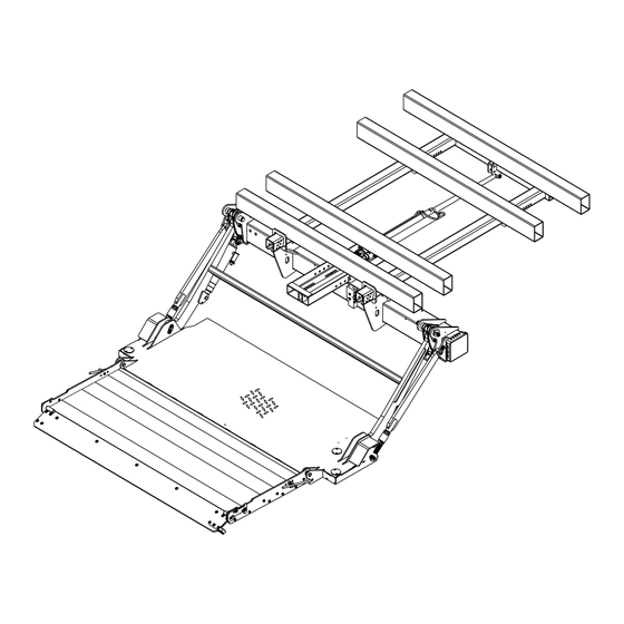
Owner‘s Manual ILSL 30/40 General View of Liftgate Sub-Frame Mount Assembly w/ Rails Liftarm Hyrdraulic Pump/Motor (Inside) 24" Parallel Aluminum Retention Ramp Steel Main Aluminum Tip Platform Center of Gravity Rev. 1.3... -
Page 12: Maximum Load And Placing Of Load On Platform
Owner‘s Manual ILSL 30/40 Maximum Load and Placing of Load on Platform Every INTERLIFT Liftgate is rated up to a maximum load. The point of maximum load is rated at a defined distance. The center point of maximum load is at 24” from the outside of the trailer body to center of load. Trailer Body 24"... -
Page 13: Operation Of Liftgate
Owner‘s Manual ILSL 30/40 Operation of Liftgate Operation by Control Box/Hand Control NOTE: Never slide platform in or out with a load on the platform. 1. Power the liftgate by turning the ON/OFF switch down. ILSL • To operate this liftgate read and understand the operating decals and manuals. - Page 14 Owner‘s Manual ILSL 30/40 4. Use the Lift switch Down to lower the platform to approximately 3“ off the ground. Unfold the platform tip manually by using the straps. Use Lift switch Down again to lower platform to the floor. Slide 3"...
- Page 15 Owner‘s Manual ILSL 30/40 To Store Liftgate 1. When platform is on the ground, use the Lift switch Up to get the platform 3“ off from the ground. Manually fold the tip of the platform. Slide Lift 3" Down 2. Use the Slide switch In until the sliding plates hit the stop bolt in the rear of the sliding rail. Slide Stop Bolt Lift...
-
Page 16: Operation By Foot Control (Optional)
Owner‘s Manual ILSL 30/40 Operation by Foot Control (Optional) Lower Platform: Step on the front foot control and hold, wait three seconds before stepping on the rear foot control. Raise Platform: Step on the rear foot control and hold, wait three seconds before stepping on the front foot control. If the platform is not responding to the controls within three seconds, repeat steps above. -
Page 17: 3-Button Flush Mount Control, Vertical Mount (Optional)
Owner‘s Manual ILSL 30/40 3-Button Flush Mount Control, Vertical Mount (Optional) Raise Platform Lower Platform Push and hold Top button Push and hold the Bottom button Slide In Platform Slide Out Platform Push and hold the Top and Middle Push and hold the Botton and Middle buttons simultaneouly buttons simultaneouly 3-Button Flush Mount Control, Horizontal Mount (Optional) -
Page 18: 6-Way Wireless Remote (Optional)
Owner‘s Manual ILSL 30/40 6-Way Wireless Remote (Optional) 1. Power the remote control unit using the ON/OFF switch located on the rear side of the control 2. Reference illustration below for liftgate operation(s). Slide Out (A) Slide In (B) Slide platform Slide platform in to out from stored position... -
Page 19: Platform Cart Stop
Owner‘s Manual ILSL 30/40 Platform Cart Stop Aluminum Platform Cart Stops 1. Push the cart stop latch out toward the curb side. The cart stop will spring open automatically once the latch has been moved from its original position. 2. To close the cart stops, push the cart stop latch inward towards the street side. After the latch is in place, close each cart stop by pushing/stepping on each stop. -
Page 20: Steel Platform Cart Stops
Owner‘s Manual ILSL 30/40 Steel Platform Cart Stops 1. Each cart stop is equipped with a retaining latch. Push each latch inward to open the cart stop. The cart stop will automatically spring open once the latch has been pushed. 2. -
Page 21: Aluminum Retention Ramp (Arr)
Owner‘s Manual ILSL 30/40 Aluminum Retention Ramp (ARR) Platform Tip Section Aluminum Retention Ramp (ARR) Slide Latch Slide Latch Square Slot Circular Slot 1. To open the ARR, strike the slide latch on the front to slide it back so the square pin ends up in the round slot of the slide latch. - Page 22 Owner‘s Manual ILSL 30/40 2. Use the ARR to load cargo on to the platform. To secure the cargo from sliding off the platform, use the handle to rotate the ARR to a 90 degree position. Once the ARR is standing at 90 degrees, slide the latch forward so the square pin of the ARR is in the square slot of the sliding latch, locking the ARR in place.
-
Page 23: Preventive Maintenance And Quick Check
Owner‘s Manual ILSL 30/40 Preventive Maintenance and Quick Check The ILSL needs preventive maintenance to perform at its fullest capability. Lubricate and inspect regularly. Also, check on hoses, cables, controls, etc. and make sure these components are not damaged. REPAIR OR REPLACE IMMEDIATELY FAULTY PARTS Maintenance and Care The following “inspection and maintenance”... -
Page 24: Lubrication
Owner‘s Manual ILSL 30/40 Lubrication Properly lubricated, the ILSL series INTERLIFT Liftgates will ensure longevity. Lubricate the liftgate at the same time as the trailer. Grease more frequently if the liftgate is heavily used. The liftgate should be greased every 500 cycles (depending on use – estimated every 3 month). All bearing points must be lubricated in accordance with the maintenance intervals. -
Page 25: Checking And Changing The Oil
Owner‘s Manual ILSL 30/40 Checking and Changing the Oil From the manufacturer, the ILSL liftgates include Hydrex MV Arctic 15 hydraulic fluid. The hydraulic reservoir will be filled to maximum level by the manufacture (2“ from the top of the reservoir). 2"... - Page 26 Owner‘s Manual ILSL 30/40 NOTES Rev. 1.3...
-
Page 27: Decal Placement And Inspection
Max. Circuit Breaker Reset (must be located at the circuit breaker) ATG-WLH Warning: Liftgate can crush ATG-CTN Caution: Always stand clear of platform area ATG-RESET Circuit Breaker Protection ATG-FT Notice for Foot Control (if applicable) ATG-WNG Warning: Use handle to open P-2032626 Palfinger Logo Rev. 1.3... - Page 28 Owner‘s Manual ILSL 30/40 ILFP / ILSL BEFORE OPERATING LIFT, BE SURE YOU UNDERSTAND: • To operate this liftgate read and understand the MAXIMUM LOAD CAPACITY operating decals and manuals. 1. Improper operation of this lift gate can result in serious personal injury. Do 3000 LBS not operate unless you have been properly instructed, have read, and are •...
-
Page 29: Quick Check List
Owner‘s Manual ILSL 30/40 Quick Check List 1. Operate the liftgate throughout its entire operation and check for noise and damage such as bent parts or cracked welds. 2. Inspect all welds and fasteners that attach the mount frame to the truck. All pins and bolts that connect the liftarm to the mount frame and to the platform. -
Page 30: Troubleshooting
Owner‘s Manual ILSL 30/40 Troubleshooting ATTENTION: Please check the following points before identifying any faults. Serious injuries are possible from tools short circuiting main battery connections. Do not leave tools or other equipment that may cause shorts around the battery. •... - Page 31 Owner‘s Manual ILSL 30/40 2. Check the circuit breaker at the main batteries. Every truck has a circuit breaker on top of the main battery or if you have a studio unit, or a trailer, you will also find an auxiliary battery kit as shown in the illustration below. If the circuit breaker reset tab is exposed, push it back in as shown on the decal ATG-BKR next to the circuit breaker or on battery box lid.
- Page 32 Owner‘s Manual ILSL 30/40 3. Are the vehicle batteries charged? Check batteries and the truck/trailer charging system. Start truck and run engine in fast idle for charging the batteries. If liftgate starts working, recharge and load test batteries. 4. Check the fuse(s) at the control board and battery. The control board inside the hydraulic power unit box has two 15 Amp fuses and at the batteries there should be a 20 Amp fuse.
-
Page 33: On/Off Switch Is On But All Functions Are Dead
Owner‘s Manual ILSL 30/40 ON/OFF switch is ON but all functions are dead. Possible malfunctions: 1. Short in hand held remote or its wire, unplug hand held control at J31. Remove J1 plug for 5 seconds. Reinstall J1, try main control board switches. If gate operates the problem is in the hand held control or its wiring. -
Page 34: Electrical Wiring
Owner‘s Manual ILSL 30/40 Electrical Wiring Wires #2 and #4 go to postitive (+) *In-Line Fuse Wires #1 and Gr/Yl go to ground (-) Aux. Batteries **Resetable Circuit Breaker 2Ga Power Cable From Liftgate (+) ***Ground Ground Cable From Liftgate (-) 4-Conductor Power Cable from Control Board... -
Page 35: Cross Test On Single Pole Plug Charge System
Owner‘s Manual ILSL 30/40 10.1 Cross Test on Single Pole Plug Charge System A. 12V lead from tractor coil cord B. Center (+) plug on front of trailer C. Trailer Ground D. Tractor chassis ground + - + - + - + - Testing of full system using a battery load tester. -
Page 36: Electrical Schematic
Owner‘s Manual ILSL 30/40 10.2 Electrical Schematic Rev. 1.3... -
Page 37: Electrical System Codes
Owner‘s Manual ILSL 30/40 10.3 Electrical System Codes Solution 1: Code: Description: Reason: Solution 2: Solution 3: Solution 4: System OK / System OK / Control System: OFF System OK / Control System: OFF Control System: OFF System OK / System OK / Control System: ON System OK / Control System: ON Control System: ON... - Page 38 Owner‘s Manual ILSL 30/40 NOTES Rev. 1.3...
-
Page 39: Hydraulic Schematic
Owner‘s Manual ILSL 30/40 Hydraulic Schematic Functions: Lift: S4 + Motor Lower: S1 + S2 Slide Out: S8 + Motor Slide In: S7 + Motor Rev. 1.3... -
Page 40: Slide Out Function
Owner‘s Manual ILSL 30/40 Functional Description of Hydraulics Schematic Slide Out Function • As soon as the Motor starts to run, valve S8 is energized. • Oil pressure exits pump and motor under pressure to A + B ports on push pull cylinder. •... -
Page 41: Needed Information For Ordering Spare Parts And Repairs
Owner‘s Manual ILSL 30/40 Needed Information for Ordering Spare Parts and Repairs 12.1 Ordering Spare Parts In order to assure quick delivery of spare parts, please always state the following information when making orders: Liftgate model & serial number. Designation and number of the spare part in accordance with the spare parts list. Designation and number marked on the individual component (if available). -
Page 42: Contact Address
Owner‘s Manual ILSL 30/40 Contact Address 15939 Piuma Ave Cerritos, CA 90703 Phone: (562)-924-8218 Fax: (562)-924-8318 E-mail (parts order): liftgateparts@palfinger.com E-mail (technical support): technicalapplications@palfinger.com 572 Whitehead Road Trenton, NJ 08619 Phone: (609)-587-4200 Fax: (609)-587-4201 E-mail (parts order): liftgateparts@palfinger.com E-mail (technical support): technicalapplications@palfinger.com...
Need help?
Do you have a question about the INTERLIFT ILSL 30 and is the answer not in the manual?
Questions and answers