Table of Contents
Advertisement
Quick Links
Advertisement
Table of Contents

Related Manuals for Palfinger INTERLIFT ILT 35/40


Summary of Contents for Palfinger INTERLIFT ILT 35/40
- Page 1 OWNER’S MANUAL ILT 35/40 ILT-PD 35/40 ILT-WR 35/40 ILT-WR-PD 35/40 12/23...
- Page 2 Copyright © 2023 Palfinger Interlift, LLC. All rights reserved. Information in this document is subject to change without notice. Visit www.palfinger.com for up to date information and notifications. If you received this product with damaged or missing parts, contact INTERLIFT Liftgates at (888)-774-5844 Parts Order/Inquiries liftgateparts@palfinger.com...
-
Page 3: Table Of Contents
Owner‘s Manual ILT 35/40 Table of Contents Manual Updates........................5 Important Notes........................6 Attention ........................6 Important Notes ......................6 General Information ...................... 7 Improper Useage ......................8 Safety Information ........................9 Important Information ......................10 General Information ......................... 11 Before Operation ...................... - Page 4 Owner‘s Manual ILT 35/40 11.8 Hydraulic Schematic (Gravity Down) ................35 11.9 Hydraulic Schematics (Power Down) ................37 Needed Information for Ordering Spare Parts and Repairs ..........38 12.1 Ordering Spare Parts ....................38 12.2 Repairs ......................... 38 Warranty ........................... 38 Contact Address ........................
-
Page 5: Manual Updates
ILT 35/40 Manual Updates Revision Description v1.6 Updated operating instructions in Section 8.1. Added platform strap location. Added cart stop operating instructions, Section 9. Updated decal G part number, Section 10.5. v1.7 Changed the logos, from Palfinger to Interlift Rev. 1.7... -
Page 6: Important Notes
Owner‘s Manual ILT 35/40 Important Notes Attention Before starting any operations of the liftgate, please read and understand this OWNER’S MANUAL. It is intended to act as a guide for the operation personal as well as to give help with preventive maintenance but does not take place of unauthorized usage or repair by unqualified personnel. -
Page 7: General Information
Owner‘s Manual ILT 35/40 General Information REMEMBER! It is the fleet manager’s responsibility to educate the operator on the liftgate and its intended use. The operator’s attention should be drawn to the permitted load limits and an understanding of the operation to ensure the safety throughout the operation. -
Page 8: Improper Useage
Owner‘s Manual ILT 35/40 Improper Usage Some examples of improper use of the liftgate may include, but are not limited to: • Using the liftgate as an elevating work platform • Using the liftgate to push, pull, or low loads or other objects. •... -
Page 9: Safety Information
Owner‘s Manual ILT 35/40 Safety Information This manual follows the Guidelines set forth in ANSI X535.4-2007 for alerting you to possible hazards and their potential severity. ! DANGER indicates an imminently hazardous situation which, if not avoided, will result in death or serious injury. -
Page 10: Important Information
Owner‘s Manual ILT 35/40 Important Information Before Getting Started “READ FIRST” Before starting any operations of the liftgate, please read and understand this Owner’s Manual. The intention of this manual is to provide the user a guide for the operation as well as preventive maintenance. -
Page 11: General Information
3) Call your INTERLIFT Liftgates Authorized Service Center for assistance. 4) Call INTERLIFT Liftgates for assistance in the USA at 888-774-5844. You can also contact INTERLIFT Liftgates by fax (562) 924-8318 or on the internet- www.palfinger.com For technical support, contact INTERLIFT Liftgates or an authorized INTERLIFT service center. www.palfinger.com... -
Page 12: Liftgate Function And Useage Information
Owner‘s Manual ILT 35/40 Liftgate Function and Usage Information Before the operator uses the liftgate, they should be thoroughly familiar with the liftgate functions and usage according to the following: 1. Improper operation of this lift can result in serious personal injury. Do not operate unless you have been properly instructed, have read and are familiar with the operation instructions. -
Page 13: General View Of Liftgate
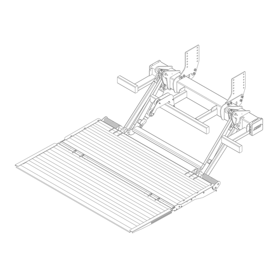
Owner‘s Manual ILT 35/40 General View of Liftgate ILT Liftgate Overview Walk Ramp Bed Extension Extension Latch Walk Ramp Up Stops Mount Frame Hydraulic Power Unit Bumper Single Action Double Action Lift Cylinders Parallel Arm Lift Arm Platform Cart Stops (Optional) Load Center of Gravity ILT Liftgate Overview... -
Page 14: Maximum Load And Placing Of Load On Platform
Owner‘s Manual ILT 35/40 Maximum Load and Placing of Load on Platform Every INTERLIFT liftgate is rated up to a maximum load. The point of maximum load is rated at a defined distance. The center point of maximum load is at 24” from the rear of the bed extension out to the platform, Fig.2. -
Page 15: Operation Of Liftgate
Owner‘s Manual ILT 35/40 Operation of Liftgate Operation by Toggle Switch/Hand Held Remote Control To Open Liftgate 1. Power on the liftgate by switching the ON/OFF switch ON. ON/OFF switch location for a truck is located in the cab, Fig.3, for a trailer it will be located on the dock bumper strut, Fig.4. Decal Strut Rocker Switch... - Page 16 Owner‘s Manual ILT 35/40 4. Use the handle on the main section to manually pull the platform away from the wheels down to the ground, Fig.8. Unhook the strap on the side of the platform and use the strap to open the tip manually, Fig.9.
-
Page 17: Hand Held Remote Control (Optional)
Owner‘s Manual ILT 35/40 Hand Held Remote Control (Optional) 1. Lowering Down Press and hold the black button to lower platform. 2. Lifting Up Press and hold the white button to raise platform. 3. Tilt Down (at Ground Level) Press and hold the button until the platform starts tilting down. 4. -
Page 18: Platform Cart Stops (Optional)
Owner‘s Manual ILT 35/40 Platform Cart Stops (Optional) 1. Push the cart stop latch out toward the curb side, Fig.15. The cart stop will spring open automatically once the latch has been moved from its original position, Fig.16. 2. To close the cart stops, push the cart stop latch inward towards the street side, Fig.17. After the latch is in place close each cart stop by pushing each stop. -
Page 19: Preventive Maintenance And Quick Check
Owner‘s Manual ILT 35/40 Preventive Maintenance and Quick Check The ILT needs preventive maintenance to perform at its fullest capability. Lubricate and inspect regularly. Also, check on hoses, cables, controls, etc. and make sure these components are not damaged. REPAIR OR REPLACE FAULTY PARTS IMMEDIATELY 10.1 Hydraulic Power Unit Access To access the Hydraulic Power Unit, open the cover on the curb side of the mount tube. -
Page 20: Maintenance And Care
Owner‘s Manual ILT 35/40 10.2 Maintenance and Care The following “inspection and maintenance” should be performed at the recommended intervals depending on operation and amount of cycles or at the time when the unit shows any signs of damage or abuse. In order to prolong the liftgates longevity it is important to maintain and perform preventive care as indicated below. -
Page 21: Lubrication
Owner‘s Manual ILT 35/40 10.3 Lubrication Properly lubricated, the ILT series INTERLIFT Liftgates will ensure longevity. Lubricate the liftgate at the same time as the truck/trailer. Grease more frequently if the liftgate is heavily used. The liftgate should be greased every 500 cycles (depending on use – estimated every 3 month). All bearing points must be lubricated in accordance with the maintenance intervals. -
Page 22: Checking And Changing The Oil (Ilt/ Ilt-Wr/Ilt-Pd)
Owner‘s Manual ILT 35/40 10.4 Checking and Changing the Oil (ILT/ ILT-WR/ILT-PD) To check fluid: To begin, lower gate to ground and tilt platform down. Open the rubber cover on the curb side of the mount tube and remove the lock bolt on the power pack tray. -
Page 23: Decal Placement And Inspection
Owner‘s Manual ILT 35/40 10.5 Decal Placement and Inspection For operator’s safety, all decals appearing in the “Decal Kit” must be placed visibly on control side of liftgate to be read by operator. This is typically a combination of decals on the liftgate and truck/trailer body. - Page 24 Owner‘s Manual ILT 35/40 Decal - A Decal - C Decal - E Decal - D Decal - B Decal - G Decal - F Decal - L Decal - H Decal – I Decal - K Decal – J Driver Side Platform Main...
-
Page 25: Quick Check List
Owner‘s Manual ILT 35/40 10.6 Quick Check List Operate the lift gate throughout its entire operation and check for noise and damage such as bent parts or cracked welds. Inspect all welds and fasteners that attach the mount frame to the truck. All pins and bolts that connect the lift arm to the mount frame and to the platform. -
Page 26: Troubleshooting
Owner‘s Manual ILT 35/40 Troubleshooting ATTENTION: Please check the following points before identifying any faults. Serious injuries are possible from tools short circuiting main battery connections. Do not leave tools or other equipment that may cause shorts around the battery. •... -
Page 27: Liftgate Will Not Power On
Owner‘s Manual ILT 35/40 11.1 Liftgate will not power on 1. Check the shut off switch. Turn ON the ON/OFF switch located inside the vehicles cab (Truck) or on the dock bumper strut (Trailer). 2. Check the circuit breaker at the main batteries. Every truck has a circuit breaker on top of the main batteries or if you have an auxiliary battery kit as shown in the illustration below. - Page 28 Owner‘s Manual ILT 35/40 3. Are the vehicle batteries charged? Check batteries and the truck/trailer charging system. Start truck and run engine in fast idle for charging the batteries. If liftgate starts working, recharge and load test batteries. Measure battery voltages: Flooded Batteries = 12.6V;...
-
Page 29: Liftgate Does No Lower Down
Owner‘s Manual ILT 35/40 11.2 Liftgate does not lower down Visually check the valves at cylinders for mechanical damage such as bent or broken valves. Open up the lid at the power pack unit and unplug the black cable (#2) with the inline fuse. Unplug cable #6 from toggle switch to both the two wire release valve harnesses. -
Page 30: Liftgate Does Not Lift Up
Owner‘s Manual ILT 35/40 11.3 Liftgate does not lift up Visually check the valves at cylinders for mechanical damage such as bent or broken valves. 2. Jump female end of cable #2 to small positive connector on motor solenoid Do NOT stay between platform and truck body, gate will raise up 3. -
Page 31: Electrical Wiring - Batteries - Truck/Trailer
Owner‘s Manual ILT 35/40 Electrical Wiring – Batteries – Truck/Trailer 11.4 *Resettable Circuit Breaker: 150 Amp Min. Replace with same amperage breaker when necessary. Ground: For optimal grounding, ground all batteries and power units to the body side rails of the vehicle. NOTICE: DO NOT attempt to jump in-line fuses with other objects other than the specified fuse. -
Page 32: Cross Test On Single Pole Plug Charge System
Owner‘s Manual ILT 35/40 11.5 Cross Test on Single Pole Plug Charge System Testing of full system using a battery load tester. Start with testing each individual battery on both tractor and trailer before proceeding to check the system: A. 12V lead from tractor coil cord B. -
Page 33: Wiring Diagram (Gravity Down)
Owner‘s Manual ILT 35/40 11.6 Wiring Diagram (Gravity Down) Rev. 1.7... -
Page 34: Wiring Diagram (Power Down)
Owner‘s Manual ILT 35/40 11.7 Wiring Diagram (Power Down) Rev. 1.7... -
Page 35: Hydraulic Schematic (Gravity Down)
Owner‘s Manual ILT 35/40 11.8 Hydraulic Schematic (Gravity Down) Rev. 1.7... - Page 36 Owner‘s Manual ILT 35/40 S1 & S2 - Release Valve for Lowering R1 & R2 - Flow Restrictor for limiting lower speed. Raise = M Lower = S1+S2 Lift Cylinder Lift Cylinder Pump Unit "A" "A" Pump Unit M-3441-0104 Pilot to Close Check Valve Pump Motor...
-
Page 37: Hydraulic Schematics (Power Down)
Owner‘s Manual ILT 35/40 11.9 Hydraulic Schematics (Power Down) S1 & S2 - Release Valve for Lowering R1 & R2 - Flow Restrictor for limiting lower speed. S5 - Shift Valve is activated upon LOWER function only. Pilot to close check valve is NOT used on Power Down. Raise = M Power Down = M + S1&2 + S5 Lift Cylinder... -
Page 38: Needed Information For Ordering Spare Parts And Repairs
Owner‘s Manual ILT 35/40 Needed Information for Ordering Spare Parts and Repairs 12.1 Ordering Spare Parts In order to assure quick delivery of spare parts, please always state the following information when making orders: Liftgate model & serial number. Designation and number of the spare part in accordance with the spare parts list. Designation and number marked on the individual component (if available). -
Page 39: Contact Address
Owner‘s Manual ILT 35/40 Contact Address 15939 Piuma Ave Cerritos, CA 90703 Phone: (562)-924-8218 Fax: (562)-924-8318 E-mail (parts order): liftgateparts@palfinger.com E-mail (technical support): technicalapplications@palfinger.com 572 Whitehead Road Trenton, NJ 08619 Phone: (609)-587-4200 Fax: (609)-587-4201 E-mail (parts order): liftgateparts@palfinger.com E-mail (technical support): technicalapplications@palfinger.com...
Need help?
Do you have a question about the INTERLIFT ILT 35/40 and is the answer not in the manual?
Questions and answers