Advertisement
Quick Links
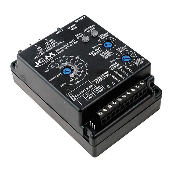
INSTALLATION, OPERATION & APPLICATION GUIDE
For more information on our complete range of American-made products –
plus wiring diagrams, troubleshooting tips and more, visit us at www.icmcontrols.com
CONNECTIONS FOR ICM333 AT 120/208/240/277 VAC
1. Remove power from system.
2. Field install a wire from Line 1
wire to Line 1 terminal.
3. Cut Line 2 wire; affix motor side
to Motor 2 terminal and line
side to Line 2 terminal.
120/208/240/277
4. Make 24 VAC and
Field
Installed
temperature probe
Wire
connections.
5. Verify wiring is correct.
6. Power up system and
check operation.
CONNECTIONS FOR ICM333 AT 480/600 VAC
1. Remove power from system.
2. Field install a wire from Line 1
wire to Line 1 terminal.
3. Cut Line 2 wire; affix motor side
to Motor 2 terminal and line
side to Line 2 terminal.
Field
4. Make 24 VAC and
Installed
Wire
temperature probe
connections.
5. Verify wiring is correct.
6. Power up system and
check operation.
CONNECTIONS FOR HEAT PUMP SYSTEM AT 120/208/240/277 VAC
1. Remove power from
120/208/240/277
system.
Field
Installed
Wire
2. Field install a wire from
Line 1 wire to Line 1
terminal.
3. Cut Line 2 wire; affix
the common from the
defrost board's fan relay
to the Motor 2 terminal
and the Line from the
contactor to the Line 2 terminal.
4. Make 24 VAC, probe and HP
connections.
Head Pressure Control with Optional Heat Pump Override
120/208/240/277
VAC
Typical
condenser fan
VAC
Capacitor
Line
Line
Motor
1
2
2
120/277
VAC
480/600
VAC
Typical
condenser fan
480/600
VAC
Capacitor
Line
Line
Motor
1
2
2
480/600
VAC
VAC
COM
Defrost Board
Capacitor
Line
Line
Motor
1
2
2
120/240/277
VAC
5. Verify wiring is correct.
6. Power up system and check
operation.
Regulates head pressure via temperature or pressure input
CAUTION!
Installation of the ICM333 shall be performed by trained technicians only. Adhere to
all local and national electric codes.
DISCONNECT ALL POWER TO THE SYSTEM BEFORE MAKING ANY CONNECTIONS.
SPECIFICATIONS
• Line Voltage: 120, 208, 240, 277, 480 and 600 VAC
• Control Voltage: 18 - 30 VAC
• Frequency: 50-60 Hz
• Operating Temperature: -40ºF to +176ºF (-40°C to +75°C)
• Probes:
– Temperature: Thermistor, 10K ohm at 77°F (25°C)
– Pressure: ICM380 (ordered separately)
• Heat Pump Override: 24 VAC N.C. or N.O.
• Weight: 12 ounces (341 grams)
Note: The ICM333 should be applied to motors and equipment that have been designated
by their respective manufacturers as capable of being speed controlled.
• Mounting:
– Surface mount using (2) #8 screws
– The ICM333 should be surface mounted to a clean metal or other thermally
Run
conductive surface for maximum heat dissipation
Capacitor
– It is recommended that the ICM333 be mounted away from the condenser exhaust
PSC Fan
air in order to maintain lower operating temperatures
Motor
INSTALLING AND CONNECTING THE PROBE
1. Only one probe type can be used at a time, temperature or pressure. Up to two
probes of a kind can be used in which case the control will respond to the probe that
senses the highest temperature or pressure.
2. A typical installation is shown in Appendix. The temperature probe can be attached
to the U-bend. Use the provided thermo-tape to secure the probe to the place of
Run
attachment.
PSC
3. W hen using a pressure probe, install it on the discharge line transducer fitting.
Fan
Motor
4. Temperature and Pressure probes are connected to ICM333 as shown in respective
wiring diagrams below.
Run
Capacitor
PSC
Fan
Motor
TEMPERATURE
PROBE 1
TEMPERATURE
PROBE 2
Run
PSC
Fan
Motor
CONNECTIONS FOR HEAT PUMP SYSTEM AT 480/600 VAC
1. Remove power from
system.
Fan
2. Field install a wire from
Relay
NC
Line 1 wire to Line 1
terminal.
Run
3. Cut Line 2 wire; affix
PSC
the common from the
Fan
Motor
defrost board's fan relay
to the Motor 2 terminal
and the Line from the
contactor to the Line 2 terminal.
4. Make 24 VAC, probe and HP
connections.
PRESSURE TRANSDUCER
PRESSURE TRANSDUCER
Example
480/600
Field
VAC
Installed
Wire
Line
Line
Motor
1
2
2
480/600
VAC
5. Verify wiring is correct.
6. Power up system and check
operation.
ICM333
2
1
Fan
Relay
COM
NC
Defrost Board
Run
Capacitor
PSC
Fan
Motor
Advertisement

Related Manuals for ICM Controls ICM333


Summary of Contents for ICM Controls ICM333
- Page 1 • Heat Pump Override: 24 VAC N.C. or N.O. • Weight: 12 ounces (341 grams) Note: The ICM333 should be applied to motors and equipment that have been designated by their respective manufacturers as capable of being speed controlled. • Mounting: CONNECTIONS FOR ICM333 AT 120/208/240/277 VAC –...
- Page 2 Upon reaching the 50° 122° cutout speed setting, the output voltage goes to zero volts. The yellow light turns off. SETTING THE CUTOUT SPEED ICM333 TYPICAL INSTALLATION The cutout speed dial adjusts the motor voltage range. Set the Ball Bearing Condenser Line 1...
Need help?
Do you have a question about the ICM333 and is the answer not in the manual?
Questions and answers