
Related Manuals for ITW SIMCO-ION IQ EASY MODULAR SENSOR


Summary of Contents for ITW SIMCO-ION IQ EASY MODULAR SENSOR
- Page 1 IQ EASY MODULAR SENSOR INSTALLATION AND OPERATING INSTRUCTIONS 5201337 REV A IQ EASY MODULAR SENSOR...
-
Page 2: Table Of Contents
TABLE OF CONTENTS 1. SAFETY WARNINGS ..............................1 DESCRIPTION ................................2 3. SPECIFICATIONS ............................... 4 4. INSTALLATION ................................5 ............................5 Unpacking Mechanical Installation ..............................5 Electrical Connections ..............................9 Set-Up ..................................17 Changing the Sensor’s Number ..........................19 Changing the Sensor’s Address ...........................19 5. -
Page 3: Safety Warnings
1. SAFETY WARNINGS Simco-Ion recommends that these instructions be read completely before the installation or operation is attempted. Failure to do so could result in personal injury and/or damage to the equipment. NOTE! – Statements identified with NOTE indicate precautions necessary to avoid potential equipment failure. CAUTION! –... -
Page 4: Description
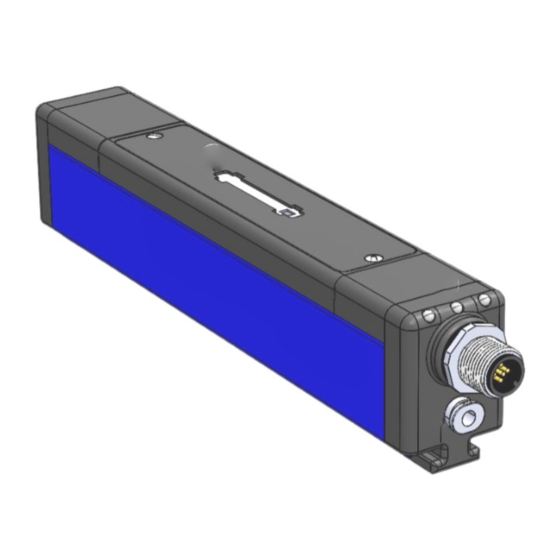
DESCRIPTION The IQ Easy Modular Sensor is an electrostatic field measuring. There are two versions of this modular sensor; one contains a single M12 input, while the other contains two RJ-45-style connectors (one on each end of the sensor). The dual-input RJ-45 sensor is designed to work in a daisy-chained (pass-through) fashion, while the M12 sensor is designed to work as a standalone device. - Page 5 1. Sensor 2. Sensor Module Retention Screws (2) 3. Indicator Lights (3) 4. Power Supply Connector 5. Purge Gas Connector Figure 1: IQ Easy Modular Sensor (M12-Style Connector) 1. Sensor 2. Sensor Module Retention Screws (2) 3. Indicator Lights (3) 4.
-
Page 6: Specifications
3. SPECIFICATIONS Power Supply IQ Power Control Station Input Voltage 24 VDC, 0.075 mA Input Connection 5-pin M12 (A-coded) Connector; RJ-45 Connector 1-2.5 psi (7-17 kPa) operating pressure 5 psi (35 kPa) max operating pressure Input Purge Gas 0.14 scfm (4 NL/min) @ 1 psi (5 kPa) 0.22 scfm (6 NL/min) @ 2.5 psi (20 kPa) Clean, dry, filtered, oil-free compressed air or nitrogen Gas Input... -
Page 7: Installation
4. INSTALLATION Unpacking Carefully remove all equipment from its carton and inspect the contents: • Check that the details on the packing slip correspond to the details of the product received. • Check that the equipment is free from damage. •... - Page 8 Figure 3: IQ Easy Modular Sensor Dimensions (M12 Connector) 5201337 REV A IQ EASY MODULAR SENSOR...
- Page 9 Figure 4: IQ Easy Modular Sensor Dimensions (RJ-45 Connector) NOTE! – SENSITIVE ELECTRONICS, RISK OF EQUIPMENT DAMAGE Do not install a sensor with charged materials present. Modular Sensor must already be connected to the power supply in the presence of charged materials. Avoid sharp blows to a Sensor Module. Dropping a Modular Sensor may cause damage to the sensor element.
- Page 10 1. Mounting Bracket 2. Sensor Bar 3. Hex Key 4. Set Screws (2) Figure 5: IQ Easy Modular Sensor Mounting Figure 6: IQ Easy Modular Sensor Positioning 12” (recommended downstream of neutralizing bar) 5201337 REV A IQ EASY MODULAR SENSOR...
-
Page 11: Electrical Connections
6. Attach the sensor using the mounting bracket and hardware supplied. See Figures 5 and 6. 7. Lock the sensor in the mounting bracket by manually tightening the set screws in the brackets. 8. Connect either the M12 or RJ-45 connector of the power cable to the Modular Sensor (depending on the connection style chosen) and route the power cable to the power supply safely. - Page 12 RJ-45-Style Connector 1. Insert the RJ-45 cable into the RJ-45 connector on the input side (the input side is the same side as the LEDs). 2. Route the other end of the lead cable to the Control Station. Remove one of the RJ-45 connector dust covers and connect the RJ-45 cable to the control station.
- Page 13 Figure 10: IQ Easy Modular Sensor Connectors (RJ-45) Figure 9: IQ Easy Modular Sensor Connector (M12) The IQ Easy Modular Sensor is available in two styles: one M12 electrical connector or two RJ-45 connectors. Both styles also have a connection at each electrical connector for purge gas. The Modular Sensor with RJ-45 connectors may be daisy-chained with up to four (4) units.
- Page 14 Figure 11: Modular Sensor to Control Station 5201337 REV A IQ EASY MODULAR SENSOR...
- Page 15 Figure 12: Modular Sensor to Control Station through BPS Power Supply 5201337 REV A IQ EASY MODULAR SENSOR...
- Page 16 Figure 13: Modular Sensor and IQ Easy Static Bar to Control Station 5201337 REV A IQ EASY MODULAR SENSOR...
- Page 17 Figure 14: Multiple Modular Sensors and IQ Easy Static Bar to Control Station 5201337 REV A IQ EASY MODULAR SENSOR...
- Page 18 Figure 15: Modular Sensor and Fantom Blower to Control Station 5201337 REV A IQ EASY MODULAR SENSOR...
-
Page 19: Set-Up
Purge Gas Connection (recommended) NOTE! – Purge gas or compressed air used with this device MUST be clean, dry, and filtered. Dirt, water, or oil in the purge gas will damage the sensors. In dirty or dusty environments low pressure purge gas may be used to prevent the sensors from becoming fouled with debris. - Page 20 NOTE! – This information (Mounting Distance) MUST be correct. It is used by the sensor for calibration. If this information is not correct, the sensor calibration will be incorrect. Overall Average: The numeric average of voltages from all sensor modules on the given sensor Device Address. Feedback Average: The numeric average of voltages from Sensors for Feedback.
-
Page 21: Changing The Sensor's Number
NOTE! – CLFB with a neutralizer is not possible when the modular sensor is configured in the charging mode. Ensure Sensor Mode is set to “Neutralizing” for CLFB applications. System Priority will automatically be set to “Neutralizer” for CLFB applications. Changing the Sensor’s Number Each Modular Sensor includes a sensor number switch located under the sensor’s rear (longer) cover. - Page 22 Figure 19: Control Station Home Page of a New Sensor Startup Step 2: Once the sensor appears on the Control Station (at Address 10), click on the Address 10 tile to access the device operating parameters. The first screen contains operating parameters such as the mounting distance, overall sensor average, sensor quantity, etc.
- Page 23 Figure 21: Control Station Address 10 Page 2 Step 4: Click on the forward arrow next to the “Page 2/3” text box (top right of the screen) to move to the third page of the device’s operating parameters. On Page 3, the customer can view operating parameters such as the sensor run time, device address, sensor firmware version, etc.
- Page 24 Figure 22: Control Station Address 10 Page 3 Step 5: A small window will then pop up asking which address you would like to change the sensors to. For this example, the user will click “3”, as indicated in Figure 23. As a note, when changing the address of the sensor(s), the Control Station will reposition all the sensors at the current address to the new address.
- Page 25 Figure 23: Device Address Select Screen Step 6: Once the address is changed, the green LEDs on the sensors that were moved will begin to flash until the change is completed, at which point, they will return to a solid green state. A completed address change can be seen in Figure 24.
-
Page 26: Operation
5. OPERATION The operation of the Modular Sensor is controlled through the IQ Power Control Station. In operation, a device icon appears on the IQ Power Control Station; a tab appears on the neutralizer page when a sensor is paired with the neutralizer. -
Page 27: Maintenance
6. MAINTENANCE NOTE! – Turn off the power to the modular sensor before performing any maintenance. Do not disconnect the modular sensor if charged materials are present. Cleaning Clean the Modular Sensor using a lint-free wiper moistened (but not saturated) with isopropyl alcohol. Use caution around the sensor modules and avoid contact with the sensor aperture. -
Page 28: Troubleshooting
7. TROUBLESHOOTING Signal Problem Cause Solution Control Station is off • Apply power to Control Station & turn on LEDs on sensor No supply voltage do not light • Replace cable with known good cable Wiring problem • Change connection at the Control Station •... -
Page 29: Parts And Accessories
8. PARTS AND ACCESSORIES Item Part Number Cable for connecting Modular Sensor to Control Station / another Modular Sensor with RJ-45 connectors at both ends. 0.3 meter (1 foot) 4520828 0.9 meter (3 foot) 4520785 2.1 meter (7 foot) 4520786 4.3 meter (14 foot) 4520787 7.6 meter (25 foot) -
Page 30: Warranty
9. WARRANTY This product has been carefully tested at the factory and is warranted to be free from any defects in materials or workmanship. Simco-Ion will, under this warranty, repair or replace any equipment that proves, upon our examination, to have become defective within one year from the date of purchase. The equipment being returned under warranty should be shipped by the purchaser to Simco-Ion, 2257 North Penn Road, Hatfield, PA 19440, with transportation prepaid and insured for its replacement cost. - Page 31 Simco-Ion 57 North Penn Road Hatfield, PA 19440 (215) 822-6401 (800) 203-3419 www.simco-ion.com customerservice@simco-ion.com © 2023 Simco-Ion. Printed in the U.S.A. 5201337 REV A IQ EASY MODULAR SENSOR...
Need help?
Do you have a question about the SIMCO-ION IQ EASY MODULAR SENSOR and is the answer not in the manual?
Questions and answers