Table of Contents
Advertisement
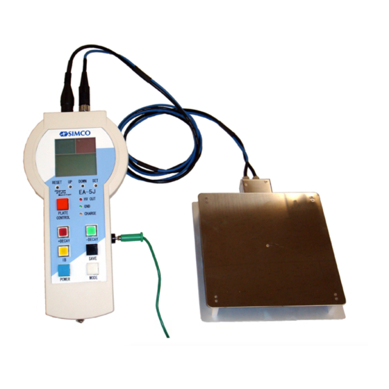
Simco-Ion Handy Charge Plate Monitor
INSTRUCTIONS
Installation/Operation/Maintenance
CAUTION
It is important that these instructions be read and understood
before attempting to install or operate the equipment. Failure to
do so could result in serious personal injury and/or damage to
the equipment. At the end of this manual, a written warranty is
provided. This should be preserved carefully.
Model EA-5J
INST-09052212
Advertisement
Table of Contents

Related Manuals for ITW Simco-Ion EA-5J


Summary of Contents for ITW Simco-Ion EA-5J
- Page 1 INST-09052212 Simco-Ion Handy Charge Plate Monitor Model EA-5J INSTRUCTIONS Installation/Operation/Maintenance CAUTION It is important that these instructions be read and understood before attempting to install or operate the equipment. Failure to do so could result in serious personal injury and/or damage to the equipment.
-
Page 2: Notes To Users
Notes to users WARNING This equipment is not constructed for classified hazardous environment. It cannot be used where it will be exposed to ignitable or corrosive materials and gases. CAUTION This equipment is intended for use in electrostatic processes that are free from water, oil, solvent and other conductive contaminants. -
Page 3: Receipt Of Equipment
Thank you for buying Simco-Ion products. This equipment will meet your expectations and provide safe operation when it is properly installed and maintained. Receipt of equipment Please carefully remove the equipment from the carton and inspect. Note any damage that might have occurred during shipment. -
Page 4: Table Of Contents
Contents Notes to Users ..................page 1 Receipt of equipment................page 2 Packing articles and accessories..............page 2 Contents....................page 3 Section 1. General description..............page 4 Section 2. Features...................page 5 Section 3. Specification ................page 6 Section 4. External view................page 10 Section 5. Setup..................page 12 Section 6. -
Page 5: Section 1. General Description
Section 1. General description Simco-Ion Model EA-5J Charge Plate Monitor is a compact instrument used for measuring the ionizer's performance. It is small, portable, handy and easy to use. It was designed to provide quantitative, accurate measurements for a variety of air ionization tests. -
Page 6: Section 2. Features
Section 2. Features The special features of EA-5J are; ● Compact and light body Multi function micro-computer chip ● Large digital display ● Rechargeable battery ● Automatic mode for continuously measurement ● 1,000 data saving into an internal memory ● Measuring time can be chosen ●... -
Page 7: Section 3. Specification
Section 3. Specification 3.1 Controller EA-5J Measurement mode: Manual mode, Auto mode and PC mode Manual mode Ion balance mode: Display shows the plate voltage. ① - LCD display renewal rate can be set: 0.2, 1, 5 and 10 seconds. 0.2 sec.: Average value of 10 points data excluded the maximum and minimum value for 20 ms is showed on the display. - Page 8 PC mode Data transfer: The memorized data can be copied in CSV format by connecting with a personal computer using a USB cable. LCD display: Digital numerical value, character, illustration and bar graph are displayed. Bar graph: It shows the plate voltage and the decay time. Right side;...
- Page 9 Maximum supply voltage: +/- 1,200 V Accuracy: +/- 10%, +/- 1 digit Indicated value Ambient conditions: 10 ~ ℃ and less than 60 %RH Beep sounds: Beep sounds when Power is turned on or the measurement end. Interface: In accordance with USB 2.0. Analog output: Voltage output Load resistance 20 k or more Ω...
- Page 10 3.2 Sensor plate CPM LPS Plate size: 150 150 mm, t = 0.8 mm × Plate capacity: 20 pF +/- 2 pF Insulation resistance: 1 > × Ω Cable length: Signal cable and HV cable; 1.5 m Overall size: 160 W 190 D 26 H )×...
-
Page 11: Section 4. External View
Section 4. External view Front view Connector side - page 10 -... - Page 12 LCD display Sensor plate CPM-LPS - page 11 -...
-
Page 13: Section 5. Setup
Section 5. Setup 5.1 Setup Connect the sensor plate to the controller. Be sure that the Plate signal connector and the HV connector are connected to the controller correctly. For proper measurement, EA-5J should be grounded on the right side grounding terminal by the grounding lead provided with the equipment. - Page 14 5.2 Battery charging EA-5J has an internal battery. It can be charged by the USB terminal on the right side. Even charging the measurement can be done. When the POWER button blue pressed, the battery condition is displayed on the left side of LCD as shown in the figure below.
- Page 15 5.3 Initial screen As POWER button blue is pressed, the sensor plate is grounded and automatic measurement mode displayed as shown in the right figure. The measurement mode can be changed by pressing MODE button white shown in the figure below. Initial display Auto mode Au PC Mode Pc...
- Page 16 5.4.1 Measurement condition setting in ion balance measurement mode When manual mode is displayed, the measurement mode can be changed to ion balance mode ib by pressing the ion balance mode button IB yellow . Auto mode PC mode Manual mode Ion balance mode Flow of LCD display Press SET button...
- Page 17 LCD display renewal rate setting ① EA-5J converts the analog signal from the sensor to digital signal every 20 ms. The digital signal is calculated automatically except the maximum and the minimum value according as following four kinds of renewal rate for the length of time. LCD display : Renewal rate number of points 0.2 : 0.2 seconds 10 points 1.0 : 1.0 second 50 points...
- Page 18 Bar graph setting ③ The correspondence of each bar of the bar graph 15 pcs. for each polarity to the voltage can be chosen from following four kinds of setting. LCD display : Voltage per one bar 15 : 1V 30 : 2V 150 : 10V 300 : 20V...
- Page 19 Stop voltage setting ① In the decay time measurement, the EA-5J monitors the time taken for the plate to discharge from the start voltage 1,000 V to the stop voltage. This stop voltage can be set from 5 to 100 V in 5 V increments or decrements by pressing UP/DOWN button.
- Page 20 Threads on the back of the sensor plate Measurement scenery - page 19 -...
-
Page 21: Section 6. Manual Mode Measurement
Section 6. Manual mode measurement 6.1 Ground connections During measurement of the ionizer performance, the accuracy might be affected by the static charge on the person and objects of circumference. Ground the person using a wrist strap etc. EA-5J must be also grounded by connecting a grounding lead to the ground terminal on EA-5J. - Page 22 The measurement is continued until the setting time. Press PLATE CONTROL ③ button again to stop measuring if the setting time is continuous con . HOLD sign is displayed on the LCD at the end of the measurement. During measurement Measurement end LCD display ④...
- Page 23 Press PLATE CONTROL button to measure again, if needed. If MODE ⑤ button is pressed, it returns to the manual mode Ma . 6.3 Decay time measurement mode Turn the power on by pressing POWER button blue . Press MODE button twice. ①...
- Page 24 CAUTION In the decay time measurement, it is necessary to apply DC high voltage to the plate. The voltage should be 1,000 V or higher. If the insulation resistance of the sensor plate is low by dirt or short circuit of conductive lint such as hair etc., it is not reached to the enough voltage then the red LED, HV OUT lights continuously.
- Page 25 The sensor plate is isolated after the end of charging if the charged voltage reaches ④ to the enough voltage. The plate voltage will be decreased by airflow of ions from the ionizer. The internal discharge timer will start when the plate voltage reaches 1,000 volts.
- Page 26 CAUTION The timer starts when the plate voltage reaches 1,000 volts and it stops when the plate voltage reaches the setting voltage. If there are insufficient ions because of the ionizer failure etc., the timer cannot stop by the fact that the plate voltage does not reach the setting voltage.
-
Page 27: Section 7. Auto Mode Measurement
Section 7. Auto mode measurement 7.1 Ground connections During measurement of the ionizer performance, the accuracy might be affected by ① the static charge on the person and objects of circumference. Ground the person using a wrist strap etc. EA-5J must be also grounded by connecting a grounding lead to the ground terminal on EA-5J. - Page 28 Turn on the power of an ionizer. Press PLATE CONTROL button red . The ② measurements start automatically in order of positive decay time, negative decay time and ion balance. Press PLATE CONTROL button red when auto mode is displayed. Positive decay time measurement starts A LED in +DECAY button lights The plate is grounded and digital zero activation.
- Page 29 CAUTION In the decay time measurement, it is necessary to apply DC high voltage to the plate. The voltage should be 1,000 V or higher. If the insulation resistance of the sensor plate is low by dirt or short circuit of conductive lint such as hair etc., it is not reached to the enough voltage then the red LED, HV OUT lights continuously.
- Page 30 After the measurements, if the following buttons are pressed, each LED in the button ④ lights and each measured data will be displayed. As the LED in IB button lights, if + DECAY button or -DECAY button is pressed, the maximum voltage peak value or the minimum voltage valley value...
-
Page 31: Section 8. Saved Data Copy
Section 8. Saved data copy 8.1 Cable connections The saved data in auto mode can be copied in CSV or TXT format by connecting ① EA-5J with a personal computer. Prepare a USB cable USB A - USB Mini-B Connect USB Mini-B of the cable to a USB terminal on the EA-5J and connect the USB A to the computer. - Page 32 In next screen, specify COM3, COM4 or COM5 ④ in a column of "Connect using". Click "OK" button. ⑤ When "COM* Properties" is displayed, specify all of properties in the "Port Settings" as follows; Bit per second : 9600 Data bits Parity : None Stop bits...
- Page 33 8.3 Saved data copy Click "Capture Text" in the "Transfer" as shown below. ① Input a suitable file name and click "Start" button. ② The initial screen is displayed again. Press keys "Shift + D" on the key board. The ③...
- Page 34 The saved file is in ".csv" or ".txt" format and the data is in order of follows. ⑥ Storage number, Positive Decay time, Negative Decay time, Average voltage of Ion balance, Maximum voltage of Ion balance Peak value , Minimum voltage of Ion balance valley value CAUTION If there is a case of overtime in the decay time measurement, the data will be saved...
-
Page 35: Section 9. Tables Of Functions
Section 9. Tables of functions 9.1 Button switches Character Operations Unit Additional color character POWER Ready to start when power on Blue Measurement stop or compulsion end after power on MODE Mode can be changed whenever the button is White pressed. -
Page 36: Section 10 Troubleshooting
Section 10. Troubleshooting Trouble Cause Countermeasure LCD shows nothing or a No battery or low battery Charge the battery. part is missing. Malfunction of the battery Repair or replacement of the battery is needed. Malfunction of the LCD Repair or replacement of the LCD or PCB is needed. -
Page 37: Section 11 Dimensional Drawings
Section 11. Dimensional drawings - page 36 -... - Page 38 - page 37 -...
-
Page 39: Simco-Ion Equipment Repair Warranty
Simco-Ion EQUIPMENT REPAIR WARRANTY Simco-Ion equipment has been carefully tested and inspected at the factory and is warranted to be free from any defects in materials or workmanship. Simco Japan, Inc. will, under this warranty, repair or replace any equipment, which proves upon their examination, to have become defective within the Warranty period from the date of shipment. - Page 40 SIMCO JAPAN, INC. 1-2-4, Minatojima-Nakamachi, Chuo-ku, Kobe, 650-0046, Japan Phone: +81-78-303-4651 Fax: +81-78-303-4655 WEB: http://www.simcoion.jp/ INQUIRY e-mail: info@simcoion.jp INST-0905221...
Need help?
Do you have a question about the Simco-Ion EA-5J and is the answer not in the manual?
Questions and answers