Table of Contents
Advertisement
Quick Links
Advertisement
Table of Contents

Related Manuals for Maxtang ALD-75


Summary of Contents for Maxtang ALD-75
- Page 1 ALD-75 ATX Motherboard...
- Page 2 Copyright © 2023 Shenzhen Maxtang Computer Co., Ltd. All rights reserved. No part of this publication may be reproduced, copied, stored in a retrieval system, translated into any language, or transmitted in any form or by any means, electronic, mechanical, photocopying, or otherwise, without the prior written consent of Shenzhen Maxtang Computer Co., Ltd (hereinafter referred to as “Maxtang”).
-
Page 3: Ald75 Motherboard
Shenzhen Maxtang Computer Co., Ltd ALD75 Motherboard User Manual (Version 1.0) Version: Description Issue Date: V0.5 Initial Version 2022/06/08... -
Page 4: Table Of Contents
Shenzhen Maxtang Computer Co., Ltd Contents ALD75 Motherboard ................1 User Manual ..................1 (Version 1.0) ..................1 Chapter 1 Product Introduction ......................4 1.1 Brief Introduction ......................4 1.2 Parameters ........................4 1.3 Connector Diagram ......................5 Chapter 2 Hardware ................6 2.1 Installations ........................6 2.2 Jumper Setting ........................6... - Page 5 Shenzhen Maxtang Computer Co., Ltd 3.3.8 Hardware Monitor .....................22 3.3.9 Watch Dog Configuration ...................23 3.3.10 S5 RTC Wake Settings ....................24 3.3.11 USB Configuration ....................25 3.3.12 Network Stack Configuration ...................26 3.3.13 CSM Configuration ....................27 3.3.14 NVMe Configuration ....................28 3.4 Chipset ..........................29 3.4.1 PCH-IO Configuration ....................30...
-
Page 6: Chapter 1 Product Introduction
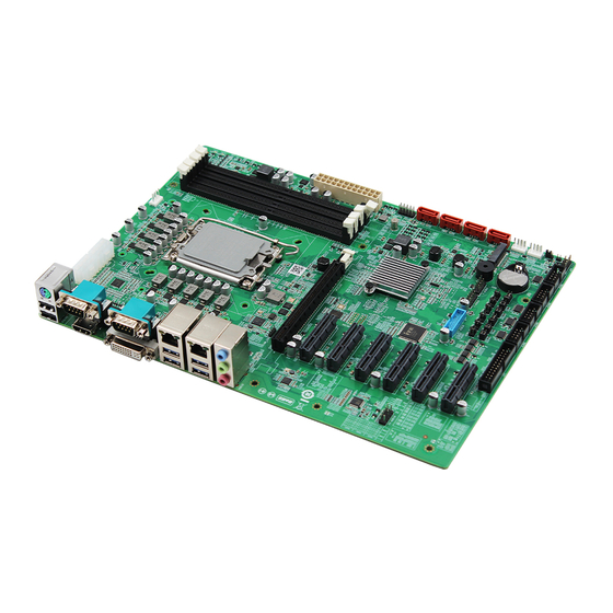
Shenzhen Maxtang Computer Co., Ltd Chapter 1 Product Introduction 1.1 Brief Introduction The ALD-75 is an ATX motherboard based on the Intel Alder Lake-S (FCLGA1700 socket) processor with Z690 chipset. 1.2 Parameters CPU: PCH Z690 + Intel Alder Lake-S series processor Memory: 4x UDIMM DDR4-3200MHz, maximum capacity for single slot:32GB, maximum memory capacity in total: 128GB. -
Page 7: Connector Diagram
Shenzhen Maxtang Computer Co., Ltd 1.3 Connector Diagram ATX3 CPU-FAN ATX2 2*USB2.0+PS/2 COM1+HDMI USB-PWR COM2+DVI-I 4*UDIMM 2*USB3.2+LAN2 2*USB3.2+LAN1 ATX1 LAN_LED AUDIO PCIE16X JGPIO PCIE2X M.2_N SATA1~4 2*USB3.2 4*USB2.0 FP-AUDIO SYS-FAN2 SYS-FAN1 5*PCIE4X JCOM6 JCOM5 JCOM4 JCOM3... -
Page 8: Chapter 2 Hardware
Shenzhen Maxtang Computer Co., Ltd Chapter 2 Hardware 2.1 Installations Please refer to the following steps for installations: Read the user manual carefully to make sure all the adjustments on the ALD75 are correct. Installing the Memory: ⚫ Press the ejector tab of the memory slot outwards with your fingertips. -
Page 9: Display Interfaces
Shenzhen Maxtang Computer Co., Ltd 2.4 Display Interfaces The board is equipped with one HDMI2.0b standard interface (supporting HDCP 2.3) and one DVI-I interface (compatible with analog and digital signals). 2.5 Storage (Screen Printing: SATA1, SATA2, SATA3, SATA4, M.2-N) The board provides 1 x M.2_Key M type 2280 for NVMe/SATA SSD, 4 x SATA3.0 standard interfaces. -
Page 10: Audio (Screen Printing: Fp-Audio)
Shenzhen Maxtang Computer Co., Ltd 2.7 Audio (Screen Printing: FP-AUDIO) The board features Realtek High-Definition Audio Codec, interface colored blue is the audio input connector (Line-in), colored green is the audio output connector (Line-out), and colored pink is the microphone input connector (MIC-in). The FP-Audio is the front audio pin (2.54mm spacing). - Page 11 Shenzhen Maxtang Computer Co., Ltd COM Pin Definition (Screen Printing: JCOM3, JCOM4, JCOM5, JCOM6) Signal Signal COM5, COM6 RS232 RS485 RS422 DATA- DATA+ (NC) (NC) (NC) (NC) (NC) (NC) (NC) (NC) (NC) (NC) COM5, COM6 Jumper Setting Interface RS232 RS485...
-
Page 12: Lpt (Screen Printing: Lpt)
Shenzhen Maxtang Computer Co., Ltd JCOM1-P, JCOM2-P, JCOM3-P, JCOM4-P, JCOM5-P, JCOM6-P Setting Function Close Close Close Only one of the three pin sets mentioned above can be short-circuited. 2.10 LPT (Screen Printing: LPT) The board provides a 2x13-pin parallel port, it requires an adapter cable to convert it into a standard parallel interface for use. -
Page 13: System Fan/Cpu Fan Socket (Screen Printing: Cpu-Fan, Sys-Fan1, Sys-Fan2,)
Shenzhen Maxtang Computer Co., Ltd (NULL) (NC) 2.12 System Fan/CPU Fan Socket (Screen Printing: CPU-FAN, SYS-FAN1, SYS-FAN2,) The board provides one 4Pin CPU fan socket for smart cooling, two 4Pin system fan sockets. CPU Fan Definition (screen printing: CPU-FAN) Signal... -
Page 14: Lan (Screen Printing: Lan1, Lan2, Lan_Led)
Shenzhen Maxtang Computer Co., Ltd +12V +12V +3.3V 8PIN DEFINTION (screen printing: ATX2, ATX3) Signal Signal +12V +12V +12V +12V 2.14 LAN (Screen printing: LAN1, LAN2, LAN_LED) The board features two high-speed ethernet controllers, which include 1x Intel i219 Date Rate Per Port: 1.0 Gbps plus 1x Intel i225 Data Rate Per Port: 2.5 Gbps. - Page 15 Shenzhen Maxtang Computer Co., Ltd remove the jumper cap. Reinsert the jumper cap onto the 2nd and 3rd pins of JCMOS (Note: Closing pins 1 and 2 clears the CMOS). Start the computer and press the <Del> key to enter the BIOS. Load optimized default values, save the settings, and exit.
-
Page 16: Chapter 3 Bios Setup
Shenzhen Maxtang Computer Co., Ltd Chapter 3 BIOS Setup 3.1 Entering the BIOS Turn on the computer and press <Delete> entering the BIOS After the computer is turned on, keep pressing F11, select enter Setup BIOS Hotkeys: F9: Restore to Factory setting. -
Page 17: Advanced Settings
Shenzhen Maxtang Computer Co., Ltd 3.3 Advanced Settings Select any of the items in the left frame of the screen. The advanced sections allow you to configure, improve and set up system features according to the preference of the CPU Configuration. All Advanced BIOS Setup options are described as follows. -
Page 18: Cpu-Power Management Control
Shenzhen Maxtang Computer Co., Ltd 3.3.2 CPU-Power Management Control 1) Intel® Speedstep®(TM): Enhanced Intel SpeedStep® Technology enables the operating system to control multiple frequencies and voltage points for optimal performance and power efficiency. 2) Intel® Speed Shift Technology: An energy-efficient frequency control method by the hardware rather than relying on OS control. -
Page 19: Gt-Power Management Control
Shenzhen Maxtang Computer Co., Ltd 3.3.3 GT-Power Management Control RC6(Render Standby): Allow/Prohibit integrated graphics card standby, the setting item has been Enabled/Prohibited, and the default setting is (Enabled). Maximum GT frequency: Maximum GT Frequency, Default max frequency. Disable Turbo GT frequency:... -
Page 20: Thermal Configuration
Shenzhen Maxtang Computer Co., Ltd 3.3.4 Thermal Configuration Enable All Thermal Functions CPU Thermal Configuration: Unlocks the temperature setting, the “Tcc Activation Offset” is the temperature adjustment option, the highest temperature is 105°C. Change the temperature by minus the number of degrees you wish to change. -
Page 21: Overclocking Performance Menu
Shenzhen Maxtang Computer Co., Ltd 3.3.5 OverClocking Performance Menu Over Clocking Feature: Disabled WDT (Watchdog Timer) Enable: Disabled BCLK Frequency... -
Page 22: Acpi Settings
Shenzhen Maxtang Computer Co., Ltd 3.3.6 ACPI Settings Enabled ACPI Auto Configuration Enabled Hibernation ACPI Sleep State S3 Video Repost: S3 Sleep Mode (Enable VGA BIOS POST function when waking up from S3 Sleep mode) -
Page 23: Super Io Configuration
Shenzhen Maxtang Computer Co., Ltd 3.3.7 Super IO Configuration Serial Port 1~6 Configuration Serial Port: Enable or disable serial port (COM). Device Setting (Read-only): Displays serial ports’ interrupt and location. Change Setting: Change serial port settings and suggest setting “Auto” as default. -
Page 24: Hardware Monitor
Shenzhen Maxtang Computer Co., Ltd 3.3.8 Hardware Monitor PC Health Status The PC health status displays CPU temperature, system temperature, fan speed, and other relevant voltage values. The above parameters have a certain range, and the system cannot run beyond these ranges. -
Page 25: Watch Dog Configuration
Shenzhen Maxtang Computer Co., Ltd 3.3.9 Watch Dog Configuration Watch Dog Configuration WDT Timeout Mode select: Minute or Second... -
Page 26: S5 Rtc Wake Settings
Shenzhen Maxtang Computer Co., Ltd 3.3.10 S5 RTC Wake Settings Wake system From S5: timing boot settings, disabled by default. Fixed Time: Select Fixed Time and the system will wake on the Hr: Min: Sec specified. Dynamic Time: Select Dynamic Time and the system will wake on a dynamic time. -
Page 27: Usb Configuration
Shenzhen Maxtang Computer Co., Ltd 3.3.11 USB Configuration Legacy USB Support Enable Legacy USB support. Disables legacy support if no USB devices are connected. Select enable will keep USB devices available under UEFI’s support. XHCI Hand-off Whether to enable the USB XCHI transfer protocol. A workaround for OS without XHCI hand-off support. -
Page 28: Network Stack Configuration
Shenzhen Maxtang Computer Co., Ltd 3.3.12 Network Stack Configuration Network Stack PXE Network boot setting, disabled by default. -
Page 29: Csm Configuration
Shenzhen Maxtang Computer Co., Ltd 3.3.13 CSM Configuration Boot Option Filter Option ROM Execution Network Storage Video Other PCI Devices... -
Page 30: Nvme Configuration
Shenzhen Maxtang Computer Co., Ltd 3.3.14 NVMe Configuration The capacity and model of the SSD will be displayed under the option after the NVMe protocol SSD has been installed. -
Page 31: Chipset
Shenzhen Maxtang Computer Co., Ltd 3.4 Chipset Select the chipset tab from the setup screen to enter the chipset BIOS Setup screen. System Agent (SA) Configuration: Northbridge configuration options, including video memory, display devices, and other options. PCH-IO Configuration: Southbridge configuration options, including hard disk, sound card equipment, and... -
Page 32: Pch-Io Configuration
Shenzhen Maxtang Computer Co., Ltd 3.4.1 PCH-IO Configuration PCI Express Configuration SATA Configuration USB Configuration Security Configuration HD Audio Configuration PCH LAN Controller State After G3 setting: S0 State (auto-start after power-on), S5 State by default. -
Page 33: Security
Shenzhen Maxtang Computer Co., Ltd 3.5 Security Administrator Password: Set the Administrator Password. User Password: Set User Password. Secure Boot: Secure boot... -
Page 34: Boot
Shenzhen Maxtang Computer Co., Ltd 3.6 BOOT Setup Prompt Timeout: Number of seconds that the firmware will wait before initiating the original default boot selection. A value of 0 indicates that the default boot selection is to be initiated immediately on boot. A value of 65535(0xFFFF) indicates that firmware will wait for user input before booting. -
Page 35: Save & Exit
Shenzhen Maxtang Computer Co., Ltd 3.7 Save & Exit Save Changes and Exit: Exit the system setup after saving the changes and continue to start the computer. Discard Changes and Exit: Exit the system setup without saving any changes and continue to start the computer.
Need help?
Do you have a question about the ALD-75 and is the answer not in the manual?
Questions and answers