Table of Contents
Advertisement
Quick Links
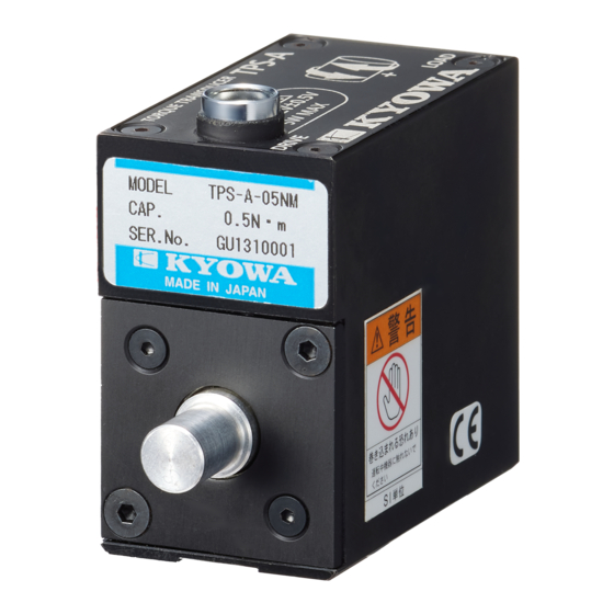
TPS-A-01NM to 2NM Torque Transducers
Thank you for purchasing this KYOWA product. Before using it,
read this instruction manual carefully. Also, keep the manual within
easy reach so that you can refer to whenever necessary.
Specifications and dimensions described in this manual could be
changed without notice. Please visit our website for the latest
version.
1. CALLING THE OPERATOR'S ATTENTION
The following cautionary symbols and headlines are used to invite
the operator's attention. Be sure to observe the accompanying
precautions in order to safeguard the operator and preserve the
performance of the instruments.
WARNING
CAUTION
2. IMPORTANT NOTICE
Unless specified, the transducer must not be used under hydrogen
environment.
3. HANDLING
3.1 Installing TPS-A
The TPS-A has DRIVE side and LOAD side as follows. Be
sure to install the TPS-A correctly.
Use a friction-joint coupling to joint the TPS-A shaft. There
may be a scratch on the shaft. However, it has no effect on the
specifications.
DRIVE
DRIVE
Provide protective coverings to the devices that are to revolve.
During operation, keep out of the devices, or the operator may
be caught in it.
Avoid such a manner as causing torque and bending moment
simultaneously to the shaft of the TPS-A.
INSTRUCTION MANUAL
Improper handling can cause serious
injury to the operator.
Cautions are given to invite the
operator's attention, in order to avoid
instrument failure or mal-function.
WARNING
It is recommended to use the Kyowa specified coupling
(optional, see "7. SPECIFICATIONS Optional accessories ").
When you do not use the Kyowa specified coupling, be sure to
use a flexible coupling.
The coupling should mount within the max. permissible
misalignment.
The TPS-A construction resists against neither water nor
moisture. Therefore, do not use it in abnormally high humidity
environments or in vacuum or corrosive atmosphere.
Where vibration occurs on the driving device and/or the driven
device, provide cushioning shaft.
Motor
PRECAUTIONS ON CE MARKING
Be sure to use the dedicated cable (TE-57R).
Wiring should be 30 m or less. Be sure to connect the shield
wire to the ground.
Do not use the product outdoors.
3.2 Fixing TPS-A
Fix the TPS-A by using the screw holes (M3×3) on the bottom
panel. (The tightening bolts are not included.)
The purpose of the fixing is to prevent the TPS-A from rotation.
When fixing the TPS-A, make sure the TPS-A shaft matches
the other shaft properly.
LOAD
LOAD
IM-T-284D Jun. 2021
CAUTION
Cushioning shaft
Torque
Transducer
TPS-A bottom panel
4×M3×3
Advertisement
Table of Contents

Subscribe to Our Youtube Channel
Related Manuals for KYOWA TPS-A-01NM


Summary of Contents for KYOWA TPS-A-01NM
- Page 1 (optional, see "7. SPECIFICATIONS Optional accessories "). Specifications and dimensions described in this manual could be changed without notice. Please visit our website for the latest When you do not use the Kyowa specified coupling, be sure to version. use a flexible coupling.
- Page 2 Example 4. CONNECTING 4.1 The connector pin No. of TPS-A and optional dedicated cables ①Connect the TPS-A shaft and other shaft by using a flexible (TE-57R, TE-58R and TE57-A-24V see "7. SPECIFICATIONS”) coupling. colors are as follows. Adjust the height of the other shaft to make sure the clearance, between the TPS-A bottom panel and mounting surface, has TE-57R Connector...
- Page 3 TE-57R Power Supply Voltage:11.5 to 12.5VDC 6-conductor (0.08mm ) vinyl shielded cable, 4.5 mm diameter by 2 m long, bared at the tip To TPS-A To measuring instrument TE-58R For connecting the optional AC adapter (SA-10A-EDS) or DC power cable (P-76). ・...
- Page 4 Tachometer TPS-A External TE-58R: (Open collector input) We recommend using the Kyowa specified power cable 12 V "P-76" (optional, see "7. SPECIFICATIONS”). Connect the power cable to the power connector. Power Supply 11.5 to 12.5 VDC (recommended: 12VDC). Red and white (twisted OC-...
- Page 5 The life of bearing which is inside of the TPS-A by the rated will be approx. 1 year. The TPS-A cannot replace the bearing TPS-A-01NM Approx. 27.6 N・m/rad Approx. 3.6×10 only. Contact Kyowa or our representatives. ・Recommend calibrate the product once a year or so.
- Page 6 For connecting the optional AC adapter (SA-10A-EDS) or DC power cable (P-76). ●Cable C: TE57-A-24V ●AC adapter :SA-10A-EDS ●DC power cable: P-76 [connector RM12BPE-4S (71)] ●Coupling: SFC-025SA2-T011-K-8B-**B (Miki Pulley Co., Ltd.) **: Shaft diameter of the target Outside drawing (with the fixtures) Website : www.kyowa-ei.com...
Need help?
Do you have a question about the TPS-A-01NM and is the answer not in the manual?
Questions and answers