Table of Contents
Troubleshooting

Subscribe to Our Youtube Channel
Related Manuals for EG4 LL-S 48V 100AH


Summary of Contents for EG4 LL-S 48V 100AH
- Page 1 S E R V E R R A C K B A T T E R Y E G 4 LL-S 4 8 V 1 0 0 A H SCAN FOR UPDATED DOCUMENTS ©2024 EG4 Electronics, LLC. All rights reserved. Version 2.2 | Information subject to change without notice.
-
Page 3: Table Of Contents
6.2.2 REQUIREMENTS FOR INSTALLATION ....................11 6.2.3 GENERAL INSTALLATION ........................12 6.2.4 INSTALLATION IN EG4 BATTERY RACK ..................13 BATTERY COMMUNICATIONS ........................14 6.3.1 CONNECTING MULTIPLE BATTERIES IN PARALLEL ..............14 6.3.2 COMMUNICATION CABLE PINOUT AND DIP SWITCH ID TABLES ..........14 INSTALLING WITH DIFFERENT EG4 BATTERY MODELS ................16... -
Page 4: Abbreviations
1. ABBREVIATIONS AWG – American Wire Gauge In-lbs. – Inch Pounds A – Amps IP – Ingress Protection Ah – Amp hour(s) kW – Kilowatt AC – Alternating Current kWh – Kilowatt-hour AFCI – Arc-Fault Circuit Interrupter L1 – Line 1 AHJ –... -
Page 5: Technical Specifications Table
2. TECHNICAL SPECIFICATIONS TABLE MODULE OPERATING PARAMETERS RECOMMENDED PARAMETER SYSTEM SETTING Voltage 51.2V Capacity 100Ah Charging Voltage (Bulk/Absorb) 56.8V 56.2V (+/-0.2V) Float 54V (+/-0.2V) 47V-45.6V (Start high, Low DC Cutoff 44.8V lower as need) Charging Current 100A (Max. continuous) 30-50A Discharging Current 100A (Max. - Page 6 GENERAL SPECIFICATIONS PARAMETER SPEC CONDITION Passive Cell Voltage Cell Balance 120mA Balance Difference >40mV Measuring Range: Cycle 40°F ‒ 212°F Temperature Accuracy Measurement (-4°C ‒ 100°C) Cycle Voltage Accuracy 0.5% For Cells/Module Measurement Cycle Measurement Range: Current Accuracy Measurement +/-200A Integral Calculation Storage/Transport/ Power Consumption (Sleep &...
-
Page 7: Safety
3. SAFETY SAFETY INSTRUCTION Before any work begins, carefully read all safety instructions, and always observe them when working on or with the battery. The installation must follow all applicable national or local standards and regulations. Consult with the local AHJ to obtain the proper permits and permissions before installation. - Page 8 WARNING: All work on this product must be carried out by qualified personnel. To reduce the risk of electric shock, do not perform any servicing other than that specified in the operating instructions unless qualified to do so 1. Read all instructions before commencing installation. For electrical work, follow all local and national wiring standards, regulations, and these installation instructions.
-
Page 9: Brief Introduction
4. BRIEF INTRODUCTION The EG4 48V LL-S rack-mounted Lithium batteries are ideal for low-voltage energy storage system applications. These batteries use lithium iron phosphate cells with the highest safety performance and a battery management system (BMS) that can monitor and collect voltage, current, and temperature of each cell within the module in real time. - Page 10 19-inch cabinet and communicates with external devices via CAN/RS485 as well as with other EG4 batteries via RS485. The modules can be connected in parallel to meet expansion requirements. Inter-battery communications support a maximum of 64 modules for the 6 DIP switch model or 16 modules for the 4 DIP switch model.
-
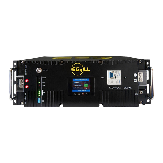
Page 11: Battery Diagram
BATTERY DIAGRAM Item Description Remarks Positive terminal M6 bolt (x2) Pin 1 & Pin 8 ‒ RS485_B RS485 port RS485 communication interface Pin 2 & Pin 7 – RS485_A Pin 4 – CAN_H CAN port CAN communication interface Pin 5 – CAN_L ON/OFF button Turn BMS on/off Reset... -
Page 12: Emergency Stop (Rsd, Ess Disconnect)
5.2 EMERGENCY STOP (RSD, ESS DISCONNECT) The optional ESS disconnect can be used to shut down all batteries and inverters (if equipped) with the push of a button. This integrated safety feature ties directly into the battery communication system via an open Battery-Com port using a standard Cat 5/6 ethernet cable. -
Page 13: Installation
The state of the battery when placed into storage will affect how long it can be stored as well as the battery’s condition when it is brought out of storage. EG4 recommends that each battery is brought to a 100% SOC (state of charge) before placing it in storage. Lithium batteries will lose a certain percentage of their total charge while in storage, depending on how long they are stored and the conditions they are stored in. -
Page 14: Requirements For Installation
6.2.2 REQUIREMENTS FOR INSTALLATION WARNING: Do not put EG4 LL-S batteries in series! The BMS and internal components are not designed to handle this setup, which could cause the modules to fail leading to damage. • Avoid exposing batteries to conductive materials, such as water, strong oxidizers, and strong acids. -
Page 15: General Installation
Tools Needed for Installation The tools required may vary depending on the mounting location. Typically, the following items are needed to install the battery into an EG4 battery rack solution or general racking: 1. 10mm socket and ratchet 2. Phillips head screwdriver 3. -
Page 16: Installation In Eg4 Battery Rack
WARNING: Do not ground rack/cabinet or door to negative or positive bus bars! In this image, there are 6 EG4 LL-S 48V 100Ah batteries wired in parallel. This battery bank still maintains the appropriate 48V needed for a system. However, the amp hour rating of this bank has increased to 600Ah. -
Page 17: Battery Communications
6.3.2 COMMUNICATION CABLE PINOUT AND DIP SWITCH ID TABLES EG4 LL-S batteries interface with an inverter by designating a “Host” battery (DIP switch ID No. 1). The ID code range is 1‒64 (1 –16 for the 4 DIP model), and the communication mode can support up to 64 modules in parallel (16 with the 4 DIP model). - Page 18 Communication Cable Pinout & Table* Description RS485-B RS485-A CAN Ground (optional) CAN High CAN Low DIP switch ID table – 4 Pin *Pinouts are for battery side; please refer to the system manual for pinout configuration on system end. DIP switch ID table – 6 Pin...
-
Page 19: Installing With Different Eg4 Battery Models
6.4 INSTALLING WITH DIFFERENT EG4 BATTERY MODELS EG4 LL-S batteries can communicate with all EG4 48V server rack modules. However, you will need to apply the proper firmware to any LL-V1 and/or Lifepower4 modules before installation. Please visit https://eg4electronics.com/resources/downloads for the latest firmware. -
Page 20: Battery Operation
7. BATTERY OPERATION LCD SCREEN Each module has a built-in HD LCD touch screen used to display important information about the cells including voltage, current, temperature, and SOC. 7.1.1 BUTTON DESCRIPTION There are 4 function buttons below the display with detailed descriptions, as shown in the table below. -
Page 21: Cell Information
7.1.3 CELL INFORMATION Check individual cell voltage by pressing the “Enter” button on the main page of the LCD screen (shown in mV). There are 2 pages. Pressing “Up” and “Down” changes the page. Page 1 Page 2 7.1.4 TEMPERATURE INFORMATION Press "Enter"... -
Page 22: Communication Protocol Selection
3. On the host battery, press and hold the “Return” key for 5 seconds to enter the “Protocol Setting”. 4. Select the corresponding RS485 program or CAN program, and press Enter. CAN Protocol Inverter RS485 Protocol Inverter P01-GRW Growatt P01-EG4 P02-SLK Sol-Ark P02-GRW Growatt P03-DY Deye P03-LUX Luxpower... -
Page 23: Bms Tools Installation And Interfacing
7.3 BMS TOOLS INSTALLATION AND INTERFACING The PC software “BMS Tools” provides real-time battery analysis and diagnostics. The battery cannot communicate with BMS Tools and a closed loop inverter at the same time. 7.3.1 DOWNLOADING AND INSTALLING BMS TOOLS Visit https://eg4electronics.com/resources/downloads to get the latest version of the software. -
Page 24: Interfacing With Bms Tools
Image A 7.3.2 INTERFACING WITH BMS TOOLS 1. Press the ON/OFF button on the battery to power off the BMS. 2. Set the DIP switch ID address of the battery to Address 64 (4-pin DIP, see image A) or Address 16 (6- pin DIP, see image B). - Page 25 7. Using an RS-485 (RJ45 Pins 1-B, 2-A) to USB-A cable, connect to the RS-485 port of the battery and then to a USB-A port on a Windows computer. 8. Set the battery’s dipswitch to ID: 64. (all dips ON) 9.
- Page 26 12. Change the “ID” to 64. 13. Select, “Start Monitoring”.
-
Page 27: Interface Menu Definition
14. The “Com State” will change from “Offline” to “Online”. The system will now monitor the battery’s values in real time. 7. To review these steps, scan the QR codes below for a video walkthrough and/or white sheet further explaining the process. BMS Tools White Sheet BMS Tools Video Walkthrough... -
Page 28: Battery Charging
This protection also aids in keeping the battery and battery cells operational for a greater number of life cycles. Each EG4 LL-S battery is specifically configured to ensure peak performance and operation with any system. -
Page 29: Alarm Description And Troubleshooting
Current protection The BMS is designed to constantly monitor the charge/discharge amperage and has built-in safeguards against exceeding specific parameters. These include built-in timers that shut off quickly in the event of short circuits, extremely high amperage and delayed shut down for amperage that is only slightly above the maximum capacity. -
Page 30: Battery End Of Life
8.3 BATTERY END OF LIFE The EG4 LL-S 48V battery is designed to last for more than 15 years when used correctly. We have worked tirelessly to ensure that our batteries will maintain a charge after thousands of cycles. -
Page 31: Eg4 10-Year Limited Warranty
Damages incurred from voltage or current spikes due to open-loop lithium battery communications EG4 product warranty is a limited warranty – EG4 limits its liability in the event of a product defect to repair or replacement in accordance with the terms of this limited warranty. EG4 is not responsible for any additional or indirect damages that may arise from the malfunctioning of the product. - Page 32 NOTES...
- Page 34 CONTACT US support@eg4electronics.com (903) 609-1988 www.eg4electronics.com...
Need help?
Do you have a question about the LL-S 48V 100AH and is the answer not in the manual?
Questions and answers