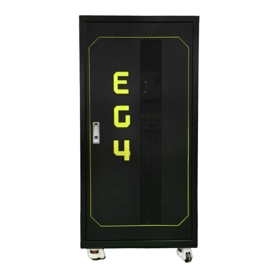
Summary of Contents for EG4 Welded Indoor Cabinet
- Page 1 U S E R M A N U A L B A T T E R Y C A B I N E T W E L D E D I N D O O R C A B I N E T SCAN FOR UPDATED DOCUMENTS...
-
Page 3: Table Of Contents
TABLE OF CONTENTS TECHNICAL SPECIFICATIONS ..........................1 ABBREVIATIONS..............................2 SAFETY .................................. 3 SAFETY INSTRUCTIONS ........................... 3 IMPORTANT SAFETY NOTIFICATIONS......................3 BRIEF INTRODUCTION ............................5 PRODUCT DESCRIPTION .......................... 5 OVERVIEW OF SYSTEM COMPONENTS....................6 INSTALLATION..............................8 UNPACKING AND INSPECTION ....................... 8 LOCATION FOR STORAGE ........................ -
Page 5: Technical Specifications
70 in-lbs. (8 Nm) and the M8 cable bolts should be torqued to 150 in-lbs. (17 Nm). (**) To ensure proof of compliance to UL9540, please contact EG4 Electronics to get a printed sticker certifying the system’s compliance. -
Page 6: Abbreviations
2. ABBREVIATIONS A – Amp(s) kW – Kilowatt AC – Alternating Current kWh – Kilowatt-hour Ah – Amp hour(s) L1 – Line 1 AHJ – Authority Having Jurisdiction L2 – Line 2 ANSI – American National Standards Institute LCD – Liquid Crystal Display AWG –... -
Page 7: Safety
3. SAFETY SAFETY INSTRUCTIONS Before beginning any work, carefully read all safety instructions, and always observe them when working on or with the cabinet and/or batteries. The installation must follow all applicable national or local standards and regulations. Consult with the local Authority Having Jurisdiction (AHJ) to obtain the proper permits and permissions before installation. - Page 8 5. Please keep children away from touching or misusing the cabinet and relevant systems. DISCLAIMER EG4 reserves the right to make changes to the material herein at any time without notice. Please refer to www.eg4electronics.com...
-
Page 9: Brief Introduction
5. BRIEF INTRODUCTION PRODUCT DESCRIPTION The EG4® Welded Indoor Cabinet is a great addition to a new or expanding Energy Storage System (ESS). Made of high-quality steel with welded joints and a durable powder coat finish, this rugged unit is resistant to wear and tear over time and is perfect for housing up to six EG4 rack-mountable batteries. -
Page 10: Overview Of System Components
5.2 OVERVIEW OF SYSTEM COMPONENTS Cabinet Diagrams Front View with door open Front View ITEM DESCRIPTION Two 1.5 in. top entry/exit points for positive/negative battery Cable Exit Points cables Depress “Push” button and turn handle clockwise to open Handle with Lock the door Swivel Casters Four heavy-duty swivel casters with adjustable feet... - Page 11 Right Side View Bottom View ITEM DESCRIPTION Side Cable Knockouts Four 2 in. cable knockouts on each side for cable entry/exit Wire Glands Four alternative cable entry/exit points...
-
Page 12: Installation
6. INSTALLATION UNPACKING AND INSPECTION Before installation, please inspect the unit. Be sure that nothing inside the package is damaged. (1) EG4 Indoor Cabinet (4) Swivel Casters (4) Wire Glands (16) M6-1.0x10 Phillips (24) M5-0.8x10 Phillips (2) Keys hex head bolts hex head bolts 6.2 LOCATION FOR STORAGE... -
Page 13: Tools Needed For Installation
(powered) busbars by accident. Failure to do so can result in severe injury and/or death. The 6 AWG red and black cables included with EG4 batteries are intended only for the connection from the battery to the battery cabinet busbars. - Page 14 3. After installing and securing all 4 casters, stand the cabinet upright and roll it into the final location. 4. Rotate the red gear located on each caster to the right to lower the rubber feet until the weight of the cabinet is supported by the rubber feet and not the wheels.
-
Page 15: Opening And Locking The Cabinet
6.3.3 OPENING AND LOCKING THE CABINET 1. Locate the button 2. Turn the door under the keyhole handle that says “PUSH” clockwise and press it to 90° and pull release the door to open the handle. door. 3. Push the door closed and rotate the handle counterclockwise to the closed position. -
Page 16: Cabinet Grounding
2. Use the M6-1.0x15 Phillips hex head bolts included in the cabinet busbars and the 6 AWG red and black DC power cables included with the EG4 batteries to connect each battery to the internal positive and negative busbars, respectively. These bolts require a 10mm socket and should be torqued to 70 in-lbs. -
Page 17: Cabinet Cabling Options
5. To ensure no connection errors, clearly identify the location of the Energy Storage System’s (ESS) positive and negative terminals—normally on the system’s inverter. Once sure of the system polarity, connect the main cabinet positive (red) and negative (black) cables to the ESS using a properly sized fuse/breaker between the battery cabinet and the system. -
Page 18: Example Cabinet Configuration
6.3.7 EXAMPLE CABINET CONFIGURATION For demonstration purposes, the image below shows a fully populated EG4® Welded Indoor Cabinet with six EG4 48V batteries. Batteries: There are four EG4-LLV2 48V/100Ah batteries (top 4), one EG4-LLV1 48V/100Ah 48VDC battery, and one EG4 LifePower4 48V/100Ah battery (bottom). -
Page 19: Troubleshooting And Maintenance
7. TROUBLESHOOTING AND MAINTENANCE Regular cleaning is essential since collected dust and debris can block battery fan filters and cause overheating. Check cable connections to avoid loose or damaged cables from interfering with network connectivity. Always use the proper torque to fasten DC power cable connections. Inspect the cabinet for physical damage such as dents or scratches that may require repairs to maintain structural integrity. - Page 20 Notes...
- Page 22 CONTACT US support@eg4electronics.com (903) 609-1988 www.eg4electronics.com...


Need help?
Do you have a question about the Welded Indoor Cabinet and is the answer not in the manual?
Questions and answers