
Subscribe to Our Youtube Channel
Related Manuals for Siemens SIMATIC MICRO-DRIVE PDC600


Summary of Contents for Siemens SIMATIC MICRO-DRIVE PDC600
- Page 1 Edition 12/2023 Equipment Manual SIMATIC MICRO-DRIVE Servo Drive System PDC600 Drive Controller www.siemens.com/drives...
- Page 3 Preface Documentation guide Product overview SIMATIC Connecting MICRO-DRIVE PDC600(F) Alarms, diagnostics, error messages and system events Equipment Manual Technical specifications Response times Dimension drawing 12/2023 A5E50502703-AB...
- Page 4 Note the following: WARNING Siemens products may only be used for the applications described in the catalog and in the relevant technical documentation. If products and components from other manufacturers are used, these must be recommended or approved by Siemens. Proper transport, storage, installation, assembly, commissioning, operation and maintenance are required to ensure that the products operate safely and without any problems.
-
Page 5: Preface
In order to protect plants, systems, machines and networks against cyber threats, it is necessary to implement – and continuously maintain – a holistic, state-of-the-art industrial security concept. Siemens’ products and solutions constitute one element of such a concept. Customers are responsible for preventing unauthorized access to their plants, systems, machines and networks. - Page 6 Industry Mall The Industry Mall is the catalog and order system of Siemens AG for automation and drive solutions on the basis of Totally Integrated Automation (TIA) and Totally Integrated Power (TIP). You can find catalogs for all automation and drive products on the Internet (https:// mall.industry.siemens.com) and in the Information and Download Center.
-
Page 7: Table Of Contents
Table of contents Preface ..............................3 Documentation guide..........................7 Product overview ..........................11 Area of application of the PDC drive controller ..............11 Properties .......................... 11 Power supply ........................15 Calculating the overload capability of the power unit............17 Connecting ............................19 Terminal assignment...................... - Page 8 Table of contents PDC600(F) Equipment Manual, 12/2023, A5E50502703-AB...
-
Page 9: Documentation Guide
Motion Control, Web server and OPC UA. You can download the documentation free of charge from the Internet (https:// support.industry.siemens.com/cs/ww/en/ps/25460). SIMATIC S7-1500 You can download general information about the SIMATIC S7‑1500/ET 200MP systems free of charge from the Internet (https://support.industry.siemens.com/cs/ww/en/view/109742691). PDC600(F) Equipment Manual, 12/2023, A5E50502703-AB... - Page 10 S7-1200 product family. In addition to the system manual, the S7-1200 Easy Book provides a general overview of the capabilities of the S7-1200 family. You can download or view the electronic manuals on the Siemens Industry Online Support (https:// support.industry.siemens.com) website.
- Page 11 (https:// support.industry.siemens.com/cs/ww/en/view/98161300). PRONETA SIEMENS PRONETA (PROFINET network analysis) allows you to analyze the plant network during commissioning. PRONETA features two core functions: • The topology overview automatically scans the PROFINET and all connected components. • PRONETA also scans: configuration of the station name, IP subnet mask and identification and maintenance data (I&M1..3)
- Page 12 Documentation guide PDC600(F) Equipment Manual, 12/2023, A5E50502703-AB...
-
Page 13: Product Overview
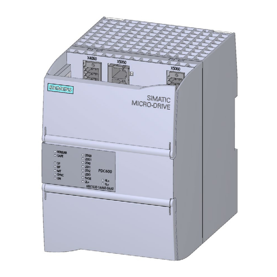
Product overview Area of application of the PDC drive controller Areas of application You can use the SIMATIC MICRO-DRIVE drive system in different industry sectors that require powerful positioning drives. SIMATIC MICRO-DRIVE has proven to be an ideal drive in numerous applications. - Page 14 Product overview 2.2 Properties View of the device The figure below shows the PDC600 drive controller. Figure 2-1 Product image PDC600 The fail-safe variant PDC600F has yellow enclosure markings as well as yellow connectors. PDC600(F) Equipment Manual, 12/2023, A5E50502703-AB...
- Page 15 Product overview 2.2 Properties Properties The PDC600 has the following technical properties: Property Description Additional information Control of EC motors The PDC600 is a motor controller for Section Connecting the motor three-phase motors (EC) with supply vol‐ (Page 26). tages to 48 V DC and permanent mag‐ nets.
- Page 16 System Manual SIMATIC MICRO-DRIVE sistor. To absorb the regenerative energy drive controller PDC (https:// of the motor, you must connect an ex‐ support.industry.siemens.com/cs/ww/e ternal braking resistor or switch on the n/view/109797859) energy recovery in the drive controller (see p0205).
-
Page 17: Power Supply
It is essential that you observe the information on recovery in the section "Energy recovery" in the System Manual SIMATIC MICRO-DRIVE Drive controller PDC (https:// support.industry.siemens.com/cs/ww/en/view/109797859). WARNING Use separate power supply units to supply the logic unit and the power unit or a filter between the shared power supply unit and the power supply. - Page 18 You can find the article numbers of the miniature circuit breakers to be used in the section "Accessories/Spare parts" in the System Manual SIMATIC MICRO-DRIVE Drive controller PDC (https://support.industry.siemens.com/cs/ww/en/view/109797859). The miniature circuit breaker must be implemented with two poles even when using PELV.
-
Page 19: Calculating The Overload Capability Of The Power Unit
Reduced current I (recovery of power unit) 10.7 A or 7.6 A recovery referenced to rated current (r0208) recovery Reference Note the detailed information on overload protection in the System Manual SIMATIC MICRO- DRIVE Drive controller PDC (https://support.industry.siemens.com/cs/ww/en/view/109774126). PDC600(F) Equipment Manual, 12/2023, A5E50502703-AB... - Page 20 Product overview 2.4 Calculating the overload capability of the power unit PDC600(F) Equipment Manual, 12/2023, A5E50502703-AB...
-
Page 21: Connecting
Connecting Terminal assignment Connection options on the PDC600 The figure below shows the connection options on the PDC600 drive controller. PDC600 6BK1630-1AA60-0AA0 ① Power supply of power unit (X5050) ② Logic supply of PDC (X5060) ③ Hardware STO (X5060) ④ SSI absolute encoder (X5060) ⑤... - Page 22 SIMATIC MICRO-DRIVE Drive controller PDC. The SIMATIC MICRO-DRIVE drive system is compatible with motors (Dunkermotoren, ebm- papst) and connecting cables (Harting, KnorrTec) of proven product partners of Siemens. This allows you to optimally combine suitable products from proven product partners for your individual application.
- Page 23 Connecting 3.1 Terminal assignment Plug connec‐ Function Maximum cable length Cable type Cable cross-section X4050 Incremental encoder sig‐ 10 m Shielded Solid and stranded sup‐ nals and supply ply cable: For differential wiring, one twisted pair per sig‐ AWG*: 22 to 16 or nal pair 0.34 mm to 1.5 mm...
- Page 24 Connecting 3.1 Terminal assignment Plug connec‐ Function Maximum cable length Cable type Cable cross-section X5060 Logic supply PDC (1L+, 20 m Solid and stranded sup‐ • < 2 m unshielded ply cable: • ≥ 2 m shielded AWG*: 20 to 16 or 0.5 mm to 1.5 mm For through-wiring for maximum permissible terminal currents, use AWG* 16 or 1.5 mm...
-
Page 25: Schematic Circuit Diagram
Connecting 3.2 Schematic circuit diagram Schematic circuit diagram The following figure shows the schematic circuit diagram of the PDC600 drive controller. ① X4060: X4060 Infeed of supply voltage for digital inputs/outputs Connection for digital outputs 24 V DC ② X4060: X5060 Infeed of supply voltage for logic unit Connection for digital inputs 24 V DC ③... -
Page 26: Connecting The Supply Voltages
• Only wire the connection plug when the supply voltage is turned off. • Observe the rules and regulations on operation described in the System Manual SIMATIC MICRO-DRIVE Drive controller PDC (https://support.industry.siemens.com/cs/ww/en/view/ 109774126). • Observe the rules and regulations described in section Product overview (Page 11). - Page 27 Connecting 3.3 Connecting the supply voltages Table 3-2 Pin assignment: Interface X4060 for supply voltage of inputs/outputs Designation Function Designation Function Reference potential Reference potential of supply of inputs/ of supply of inputs/ outputs outputs Supply of inputs/ Supply of inputs/ outputs outputs •...
-
Page 28: Connecting The Motor
(Harting, KnorrTec) of proven product partners of Siemens. This allows you to optimally combine suitable products from proven product partners for your individual application. You can find more information about the Siemens Product Partner Program on the Internet (https://new.siemens.com/global/en/company/topic-areas/partners/product-partners-... - Page 29 Pin assignment: Interface X5055 for motor phases Designation Function Motor phase U Motor phase V Motor phase W Reference Note the detailed information on the topic "Connecting" in the System Manual SIMATIC MICRO- DRIVE Drive controller PDC (https://support.industry.siemens.com/cs/ww/en/view/109774126). PDC600(F) Equipment Manual, 12/2023, A5E50502703-AB...
-
Page 30: Connecting An External Braking Resistor
Connecting 3.5 Connecting an external braking resistor Connecting an external braking resistor Connecting an external braking resistor WARNING Damage to braking resistor - Risk of fire! You must implement fire prevention measures for the external braking resistor (e.g. fire protection housing, temperature fuse). The resistance of the externally connectable braking resistor must be at least 3 ohms. - Page 31 Note the detailed information on connection of an external braking resistor in the System Manual SIMATIC MICRO-DRIVE Drive controller PDC (https:// support.industry.siemens.com/cs/ww/en/view/109774126). You can also find information on the topic of "Accessories/spare parts" in the System Manual SIMATIC MICRO-DRIVE Drive controller PDC.
- Page 32 Connecting 3.5 Connecting an external braking resistor PDC600(F) Equipment Manual, 12/2023, A5E50502703-AB...
-
Page 33: Alarms, Diagnostics, Error Messages And System Events
Alarms, diagnostics, error messages and system events Status and error display The PDC has LED displays for indicating the current operating state and the diagnostics status. The "RDY/ERR" LED indicates the status of the drive state. Table 4-1 Meaning of the LED RDY/ERR LED Meaning The drive is ready for operation. - Page 34 LEDs for the status of the drive controller in the System Manual SIMATIC MICRO-DRIVE Drive controller PDC (https:// support.industry.siemens.com/cs/ww/en/view/109774126) You can find additional information on the topic of "Interrupts" in the STEP 7 online help. PDC600(F)
- Page 35 Alarms, diagnostics, error messages and system events 4.1 Status and error display You can find additional information on the topic of "Diagnostics" and "System alarms" in function manual Diagnostics (https://support.industry.siemens.com/cs/ww/en/view/ 59192926). PDC600(F) Equipment Manual, 12/2023, A5E50502703-AB...
- Page 36 Alarms, diagnostics, error messages and system events 4.1 Status and error display PDC600(F) Equipment Manual, 12/2023, A5E50502703-AB...
-
Page 37: Technical Specifications
Technical specifications Technical specifications The following table shows the technical specifications of the PDC600 (6BK1630-1AA60-0AA0) and PDC600F(6BK1630-2AA60-0AA0) as of 09/2020. PDC600(F) Equipment Manual, 12/2023, A5E50502703-AB... - Page 38 Technical specifications 5.1 Technical specifications You can find a data sheet including daily updated technical specifications on the Internet (https://support.industry.siemens.com/cs/ww/en/ps/25460). Article number 6BK1630-1AA60-0AA0 6BK1630-2AA60-0AA0 General information Product type designation EC motor controller HW functional status FS01 Product description Control of EC motors Mean time between failures (MTBF) 100 000 h...
- Page 39 Technical specifications 5.1 Technical specifications Article number 6BK1630-1AA60-0AA0 6BK1630-2AA60-0AA0 Number of digital inputs Number of safety inputs 1; For STO, antivalent (2-pin) - 24 V DC Digital outputs Type of digital output Source output (PNP, current-sourcing) Number of digital outputs Number of safety outputs Encoder ...
-
Page 40: Drive Controller Derating
You can find information on the general technical specifications, such as standards and approvals, electromagnetic compatibility, protection class, etc., in the System Manual SIMATIC MICRO-DRIVE Drive controller PDC (https://support.industry.siemens.com/cs/ww/en/ view/109774126). Drive controller derating The maximum permissible output current for PDCs of performance class 600 W must be reduced as follows depending on the installation altitude, mounting position and ambient temperature. - Page 41 Technical specifications 5.2 Drive controller derating 1000 2000 3000 4000 Figure 5-1 Derating for PDC600(F) as a function of the installation height Derating as a function of the mounting position For vertical mounting (vertical mounting rail), the PDC600 may be operated up to a maximum ambient temperature of 40 °C.
- Page 42 Technical specifications 5.2 Drive controller derating Figure 5-2 Derating for PDC600(F) as a function of the ambient temperature Coincidence factors of inputs/outputs Also note the permissible coincidence factors of the inputs/outputs. At ambient temperatures above 40 °C, the sum of the output currents of the two outputs (DQ) must not exceed 1 A.
-
Page 43: Response Times
The response time is the time between the detection of an input signal and the change of a linked output signal. You will find the response times of the SIMATIC MICRO-DRIVE drive system on the Internet (https://support.industry.siemens.com/cs/ww/en/view/109777254). The response times of the drive enter into the calculation of the response time of the F-system. - Page 44 Response times PDC600(F) Equipment Manual, 12/2023, A5E50502703-AB...
-
Page 45: Dimension Drawing
You must take into account the dimensions for installation in cabinets, control rooms, etc. Dimension drawings of the SIMATIC MICRO-DRIVE PDC600(F) PDC600 6BK1630-1AA60-0AA0 Figure B-1 Dimension drawings of SIMATIC MICRO-DRIVE PDC600(F), front and side view (as examples, depending on mounting rail type used) PDC600(F) Equipment Manual, 12/2023, A5E50502703-AB... - Page 46 Dimension drawing PDC600(F) Equipment Manual, 12/2023, A5E50502703-AB...
Need help?
Do you have a question about the SIMATIC MICRO-DRIVE PDC600 and is the answer not in the manual?
Questions and answers