Goodwe GMK120 Quick Installation Manual
Smart meter
Hide thumbs
Also See for GMK120:
- Quick installation manual (20 pages) ,
- Quick installation manual (111 pages)
Table of Contents
Advertisement
Quick Links
Advertisement
Table of Contents

Related Manuals for Goodwe GMK120


Summary of Contents for Goodwe GMK120
- Page 1 Quick Installation Guide Smart Meter (GMK120 GMK140 GM330) V1.2-2024-02-25...
-
Page 2: General Safety
Strictly follow the installation, operation, and configuration instructions in this guide and user manual. The manufacturer shall not be liable for equipment damage or personal injury if you do not follow the instructions. For more warranty details, please visit https://en.goodwe.com/warranty. Safety Disclaimer WARNING •... -
Page 3: Personal Requirements
• In areas at risk of lightning, if the input cable of the device exceeds 10m (33ft), you are recommended to use an external lightning protection device. If the communication cables are wired with grounded metal conduits, the lightning protection device is not necessary. -
Page 4: Federal Communications Commission (Fcc) Interference Statement
Federal Communications Commission (FCC) Interference Statement This equipment has been tested and found to comply with the limits for a Class B digital device, pursuant to Part 15 of the FCC Rules. These limits are designed to provide reasonable protection against harmful interference in a residential installation. -
Page 5: Product Introduction
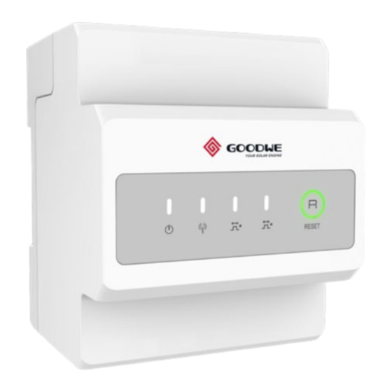
Product Introduction GMK120 Top view Bottom view L3(Reserved) Front View Side view Reset Button Indicators... - Page 6 GMK140 Top view Bottom view L3(Reserved) Front View Side view Reset Button Indicators...
- Page 7 GM330 Top view Bottom view Side view Front View Reset Button Indicators...
- Page 8 Waterproof box CT direction:House-->Grid...
-
Page 9: Wiring System
Wiring System GMK120 NOTICE Recommended cross-sectional area of the smart meter input power cable: 1mm (18AWG). Utility Grid Household Meter Hybrid Inverter Loads... - Page 10 GMK140 NOTICE Recommended cross-sectional area of the smart meter input power cable: 1mm (18AWG). Utility Grid Household Meter AC-Coupled Inverter Loads...
- Page 11 GM330 NOTICE • Recommended cross-sectional area of the smart meter input power cable: (18AWG). • Short circuit N and L2 in the three-phase three-line system. • Set the CT 's turns ratio via SolarGo App. For example, set the CT ratio to 40 if a 200A/5A CT is selected.
- Page 12 Connect CT cables NOTICE • Only applicable to GM330. • Prepare the CT. Or contact the device manufacturer for purchasing. • Specifications of the CT: 1. Choose nA/5A for the current transformation ratio of the CT. (nA: For primary current of the CT, n ranges from 200 to 5000.Set the current value depending on the actual needs.5A: The output current of the secondary current of the CT.) 2.
-
Page 13: Installation
For specific CT wirings, refer to the documents provided by the respective manufacturer. Installation Packing List x 14 [1]. GMK120:CT x 3; GMK140: CT x 6; GM330 is not equipped with CT. [2]. Only for GM330. [3]. Only for GMK120, GMK140. [4]. Optional. - Page 14 Installation and Cable Connection Installing the rail GMK120/GMK140 GMK120 and GMK140 are connected in the same way. The following illustrations take GMK120 as an example. GM330...
- Page 15 Installing the waterproof box NOTICE • Use the hole digger to drill on the waterproof box. It is suggested to drill holes and route cables on the bottom of the box, thus not influencing the performance of waterproof. • Prepare the hole digger and waterproof conduit by the customer. Φ: 6mm(0.24in) D: 40mm(1.57in)
- Page 17 Cut and connect CT cables (optional) NOTICE For GMK120 and GMK140 only: • CT cables can be cut or extended according to actual needs, and the recommended cable length is 1-30m. • Recommended cross-sectional area of CT cable wire: 1.6mm²(15AWG).
-
Page 18: Maintenance
Indicator Type Status Description Steady on Power on, no RS485 communication. Blinking Power on, RS485 communication works properly. Power light Power off. Reserved. Press the Reset button for more than 5 seconds,power Blinking light, buying or selling electricity indicator light flash: Communication light Reset the meter. -
Page 19: Technical Parameters
Technical Parameters Model GMK120 GMK140 GM330 Technical parameters Single-phase(L/N ≤ 265Vac) Split-phase(L/N≤ 265Vac) Three-phase(3- Three-phase(3-wire,L/L≤ wire,L/L ≤ 576Vac) Grid 265Vac) Three-phase(4- Three-phase(4-wire,L/N≤ wire,L/N ≤ 520Vac) 265Vac) Input Frequency 50/60Hz Rated voltage 208V, 120V / 240V 277V/480V Voltage Voltage range 0.88Un-1.1Un... - Page 20 Official Website GoodWe Technologies Co., Ltd. No. 90 Zijin Rd., New District, Suzhou, 215011, China www.goodwe.com service@goodwe.com 340-00873-01 Local Contacts...
Need help?
Do you have a question about the GMK120 and is the answer not in the manual?
Questions and answers