Table of Contents
Advertisement
Quick Links
WARNING:
FIRE OR EXPLOSION HAZARD
Failure to follow safety warnings exactly could result in serious injury, death, or property damage.
• Do not store or use gasoline or other flammable vapors and liquids in the vicinity of this or any other appliance.
• WHAT TO DO IF YOU SMELL GAS
• Do not try to light any appliance.
• Do not touch any electrical switch; do not use any phone in your building.
• Leave the building immediately.
• Immediately call your gas supplier from a neighbor's phone. Follow the gas supplier's instructions.
• If you cannot reach your gas supplier, call the fire department.
• Installation and service must be performed by a qualified installer, service agency or the gas supplier.
Please read this manual BEFORE installing and
operating this fireplace.
INSTALLER: Leave this manual with the appliance.
CONSUMER: Retain this manual for future reference.
Model: BH2613i
Ce produit peut vous exposer à des agents chimiques, y compris au monoxyde de
carbone, lesquels sont reconnus dans l'État de la Californie comme causant le cancer et
des malformations congénitales ou autres dommages au fœtus. Pour obtenir plus de
This product can expose you to chemicals including carbon monoxide, which
is known to the State of California to cause cancer, birth defects and/or other
reproductive harm. For more information, go to www.P65warnings.ca.gov
227 Industrial Park Rd. • South Pittsburg, TN 37380 •
Phone: 423-403-4031 • Web: www.breckwell.com
renseignements, veuillez consulter le site www.P65warnings.ca.gov
CALIFORNIA PROPOSITION 65 WARNING:
Report # F18-426R1
853779C-1004N
Advertisement
Table of Contents

Subscribe to Our Youtube Channel
Related Manuals for Breckwell BH2613i


Summary of Contents for Breckwell BH2613i
- Page 1 INSTALLER: Leave this manual with the appliance. reproductive harm. For more information, go to www.P65warnings.ca.gov Report # F18-426R1 CONSUMER: Retain this manual for future reference. 227 Industrial Park Rd. • South Pittsburg, TN 37380 • 853779C-1004N Phone: 423-403-4031 • Web: www.breckwell.com...
- Page 2 After-market: Completion of sale, not for purpose of resale, from the manufacturer. Note: Register your product by using your smart phone with the QR code. Save your receipts with your records for any warranty claims. You can also register your product online at www.breckwell.com/product-registration...
-
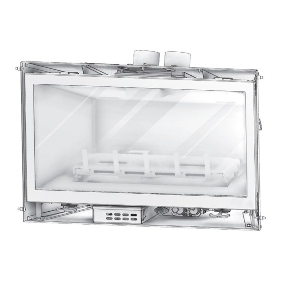
Page 3: Appliance Dimensions
Appliance Dimensions Physical Dimensions Right Side View Left Side View inches Back Width 18 - 3/4 Depth (from back of surround) C Height (to top of exhaust tube) 19 - 5/8 Width 30 - 7/16 Back of Surround to Gas Line Access 7 - 3/4 Bottom to Gas Line Access 1 - 5/8... -
Page 4: Safety Label
Safety Label NOTE: This image is only an example. The label on the actual unit will vary slightly. FOR YOUR SAFETY READ BEFORE OPERATING WARNING: If you do not follow these instructions exactly, a fire or explosion may result causing property damage, personal injury, or loss of life. -
Page 5: Requirements For The Commonwealth Of Massachusetts
Requirements For The Commonwealth Of Massachusetts INSPECTION following requirements reference various Massachusetts and national codes not contained in The state or local gas inspector of the side wall this manual. For all sidewall horizontally vented gas horizontally vented gas fueled equipment shall not fueled equipment installed in every dwelling, building approve the installation unless, upon inspection, the or structure used in whole or in part for residential... -
Page 6: Carbon Monoxide Poisoning
Before You Start • In a recreational vehicle WARNING: Read this owner’s manual carefully and • Where curtains, furniture, clothing, other completely before trying to assemble, operate, or flammable objects are less than 36” from the front, service. Any change to this appliance or its controls top, or sides of it can be dangerous. -
Page 7: Product Specifications
17. This appliance, when installed, must be electrically 21. Do not use a blower insert, heat exchanger insert, grounded in accordance with local codes or in the or any other accessory not approved for use with absence of local codes, with the National Electrical this appliance. -
Page 8: Existing Fireplace Requirements
WARNING: This appliance must be vented to the WARNING: Do not pack the open air spaces with outside. The venting system must NEVER be attached insulation or other materials. This could cause to a chimney serving a separate solid fuel burning high temperatures and may present a fire hazard appliance. -
Page 9: Vent Termination Clearances
EXISTING CHIMNEY HEIGHT • Masonry chimney: 6“ x 8“ (152mm x 203mm) minimum inside diameter • Minimum: 10 ft (3.05 m) Maximum: 35 ft (10.67 m) DETERMINE LENGTH OF EXISTING CHIMNEY 1. Remove and discard existing chimney cap. 2. It is helpful to have two people complete this step. Position one person at the fireplace and another person at the top of the chimney. -
Page 10: Minimum Termination Clearances
MINIMUM TERMINATION CLEARANCES Inside corner detail Fixed closed Fixed Operable closed Operable Legend: = Vent terminal = Air supply inlet = Air where terminal is not permitted Canadian installation US installations Clearance above grade, veranda, porch, deck, or 12” (30 cm) 12”... -
Page 11: Installation Preparation
Installation Preparation NOTE: This gas fireplace insert is approved for installation may be drilled through the lower sides or bottom of in masonry and factory-built solid fuel burning fireplaces. the firebox in a proper workmanship like manner. The access hole must be plugged with non-combustible CAUTION: Any removed parts must be capable of insulation after the gas supply line has been installed. -
Page 12: Run Vent System
RUN VENT SYSTEM CONNECT VENT PIPE TO AIR DUCT NOTE: If offsets are present in an existing chimney, 1. Place previously removed air duct into existing place a weighted rope around the pipe ends to guide fireplace opening. them through the chimney. DO NOT ATTEMPT TO TIE 2. -
Page 13: Gas Conversion (Sold Separately)
5. If necessary, level the gas insert by threading leveling bolts into nuts at the bottom of the insert (2 SECURE WITH each side). Verify appliance is properly positioned. (2) SCREWS FLEXIBLE PIPES PULL ROD Seated Air Duct (shown without venting attached for clarity purposes only) SHEET METAL SCREWS (3 TOTAL) SEALANT... - Page 14 Facing & Finishing CLEARANCES TO COMBUSTIBLES 12” (305mm) COMBUSTIBLE COMBUSTIBLE MANTEL MATERIAL 10” (254mm) 30” (762mm) 9” (229mm) CLEARANCE TO ADJACENT SIDEWALL Mantel Requirements Log, Liner, Safety Barrier, & Surround Installation Do not operate this appliance without a safety barrier. CAUTION: Do not place logs directly over burner port Only safety barriers certified with the appliance shall be holes.
-
Page 15: Glass Frame Assembly
Gas Fireplace Insert Setup GLASS FRAME ASSEMBLY INSTALL GLASS ASSEMBLY 1. Align the slots on top of the glass assembly over WARNING: Do not operate this fireplace with the the tabs at the top of the firebox while lowering the glass removed, cracked, or broken. -
Page 16: Control Board
Control Board WARNING: If burner and/or pilot have been burning, CAUTION: Check all connections for leaks with soapy use appropriate protection to avoid burns or water, whether field or factory made. damage to personal property before removing any components. DO NOT OPERATE THIS APPLIANCE WITHOUT THE SEALING GASKET (LOCATED UNDER THE CONTROL BOARD) IN PLACE. -
Page 17: Replacement Parts & Service
88309 Pass Through Gasket after use for a few months. Environmental factors 610685 Glass Door Frame Assembly beyond the control of Breckwell can cause flame 80709 Blower rectification concerns. 610981 Control Module Box Assembly... -
Page 18: Valve Assembly
VALVE ASSEMBLY Pilot Top Shutter Cable Shutter Cable Bulk Head Tube MTG Brkt Gas Pilot Shutter Adjustment Sleeve Pilot MTG Box Burner Orifice Weldment Shutter Adj. Bottom Burner Mount Plate Assembly Shutter Adj. Top Valve Assembly Assembly Mount Burner Accent Light Control Module Blower -18-... -
Page 19: Installation Checklist
Installation Checklist All items on the checklist must be completed. Correct gas pressure, proper size gas lines and gas The venting system is installed by an approved leaks are checked. service person in accordance with instructions 120 V electrical service and gas supply is installed and local codes. -
Page 20: Automatic Safety Restart
3. Up/Down Button: This button is used to increase SMART or decrease the thermostat temperature, flame height, fan speed, and accent light intensity. 4. Mode Selection Button: This button is used to toggle between the various function icons: flame height, fan speed, accent light, and rear burner (certain models). -
Page 21: Ipi And Cpi Modes
ICON DETAILS Accent Light: This function controls the accent light functions. Pressing the up button in this mode will turn Mode Button: Pressing the mode button toggles on the accent light and allow you to control the 6 levels between the various available functions: flame height, of intensity. -
Page 22: First-Time Lighting Instructions
First-Time Lighting Instructions 2. Do not attempt to light the pilot by hand; the door WARNING: must remain on this fireplace during pilot ignition, WHAT TO DO IF YOU SMELL GAS except for the first time lighting. • Do not light any fireplace. •... -
Page 23: Where Can I Find The Model And Serial Numbers
Report # F18-426 227 Industrial Park Road, South Pi�sburg, TN 37380 • Phone: (800) 750-2723 • Web: www.breckwell.com 853780 WHAT HAPPENS WHEN FIRST LIT? Step 2: High Heat Curing Cycle •... - Page 24 IS MY FLAME APPEARANCE CORRECT? will cause odor issues. Breckwell is not responsible for There are air shutters and media that can be adjusted any odor issues caused by materials used. If you have depending on your fuel and venting configuration.
- Page 25 To activate the child-lock function: Simultaneously BURNER FLAME APPEARANCE press the “MODE button” and the “UP button”. To deactivate the child-lock function: Simultaneously Soot Above Soot At Flame Tip No Soot at Flame Tip press the “MODE button” and the “UP button”. Flame Tip During the child-lock mode, none of the remote-control Dark Orange...
-
Page 26: Burner Flame Adjustments
6. Turn on remote, then turn off remote. After completing these steps, contact your authorized dealer if it won’t turn on. 7. Toggle master switch back on. 8. Press Mode button on remote. Select CPI mode to reignite the pilot. After pilot lights, turn on your remote to ignite. - Page 27 3. If flame is too “orange” or is causing sooting on viewing glass, pull air shutter knob out (open) in approx. 1/8” increments until sooting stops. Inlet Pressures Manifold Pressure Fuel Natural Gas LP Gas Fuel Natural Gas LP Gas Gas Supply Min - Max Min - Max...
-
Page 28: Troubleshooting
CAUTION: Try each new shutter setting approx. 1/2 hr. before making additional changes. Changes in burner flame can be made by re-arranging the media. Factory Set Venturi Openings Fuel Air Shutter Opening Natural Gas 1/8” (4 mm) OPEN Shutter Adjustment Controls LP Gas 1/4”... - Page 29 ON/OFF rocker switch in OFF position Gas supply turned off Check Check for multiple shut-offs in the supply line. Gas supply turned off Verify gas supply is turned on. Consult with plumber or gas supplier. Low gas supply Check LP (propane) tank. Refill if necessary. Wiring disconnection or improper wiring Check for faulty or incorrect wiring.
-
Page 30: Burner And Pilot System
• Inspect the glass for cracks, scratches, and nicks. • Verify the glass assembly is properly intact and not damaged. • Replace the glass and the assembly as necessary. • Only Breckwell will supply the replacement of glass assembly as a complete unit. -30-...
Need help?
Do you have a question about the BH2613i and is the answer not in the manual?
Questions and answers