
Related Manuals for AFRISO AZV


Summary of Contents for AFRISO AZV
- Page 1 Betriebsanleitung Operating instructions Notice technique Copyright 2024 AFRISO-EURO-INDEX GmbH. Alle Rechte vorbehalten. Version: 02.2024.0 ID: 900.000.1079...
- Page 2 Betriebsanleitung Zonenventil Copyright 2024 AFRISO-EURO-INDEX GmbH. Alle Rechte vorbehalten. Version: 02.2024.0 ID: 900.000.1079...
-
Page 3: Über Diese Betriebsanleitung
Über diese Betriebsanleitung Über diese Betriebsanleitung Diese Betriebsanleitung beschreibt das Zonenventil „AZV“ (im Folgenden auch „Produkt“). Diese Betriebsanleitung ist Teil des Produkts. • Sie dürfen das Produkt erst benutzen, wenn Sie die Betriebsanleitung vollständig gelesen und verstanden haben. • Stellen Sie sicher, dass die Betriebsanleitung für alle Arbeiten an und mit dem Produkt jederzeit verfügbar ist. - Page 4 Informationen zur Sicherheit Informationen zur Sicherheit Warnhinweise und Gefahrenklassen In dieser Betriebsanleitung finden Sie Warnhinweise, die auf potenzielle Gefahren und Risiken aufmerksam machen. Zusätzlich zu den Anweisungen in dieser Betriebsanleitung müssen Sie alle am Einsatzort des Produktes gel- tenden Bestimmungen, Normen und Sicherheitsvorschriften beachten. Stel- len Sie vor Verwendung des Produkts sicher, dass Ihnen alle Bestimmungen, Normen und Sicherheitsvorschriften bekannt sind und dass sie befolgt wer- den.
-
Page 5: Informationen Zur Sicherheit
Informationen zur Sicherheit Zusätzlich werden in dieser Betriebsanleitung folgende Symbole verwendet: Dies ist das allgemeine Warnsymbol. Es weist auf die Gefahr von Verletzungen und Sachschäden hin. Befolgen Sie alle im Zusammenhang mit diesem Warnsymbol beschriebenen Hinweise, um Unfälle mit Todesfolge, Verlet- zungen und Sachschäden zu vermeiden. -
Page 6: Vorhersehbare Fehlanwendung
Informationen zur Sicherheit Führen Sie bei der Verwendung des Produkts alle Arbeiten ausschließlich unter den in der Betriebsanleitung und auf dem Typenschild spezifizierten Bedingungen und innerhalb der spezifizierten technischen Daten und in Übereinstimmung mit allen am Einsatzort geltenden Bestimmungen, Nor- men und Sicherheitsvorschriften durch. -
Page 7: Persönliche Schutzausrüstung
Informationen zur Sicherheit Persönliche Schutzausrüstung Verwenden Sie immer die erforderliche persönliche Schutzausrüstung. Berücksichtigen Sie bei Arbeiten an und mit dem Produkt auch, dass am Ein- satzort Gefährdungen auftreten können, die nicht direkt vom Produkt ausge- hen. Veränderungen am Produkt Führen Sie ausschließlich solche Arbeiten an und mit dem Produkt durch, die in dieser Betriebsanleitung beschrieben sind. -
Page 8: Transport Und Lagerung
Transport und Lagerung Transport und Lagerung Das Produkt kann durch unsachgemäßen Transport und Lagerung beschä- digt werden. HINWEIS UNSACHGEMÄSSE HANDHABUNG • Stellen Sie sicher, dass während des Transports und der Lagerung des Pro- dukts die spezifizierten Umgebungsbedingungen eingehalten werden. • Benutzen Sie für den Transport die Originalverpackung. - Page 9 Produktbeschreibung Produktbeschreibung Das Produkt besteht aus einem Elektroantrieb und einem Ventilkörper. In dem Ventilkörper befindet sich ein Kugelventil, welches den Durchfluss des Mediums in einer Kühl- oder Heizungsanlage steuert. Produktidentifikation (Typenschild) Zur Identifikation Ihres Produkts dient das Typenschild. Das Typenschild zeigt die folgenden Daten: A.
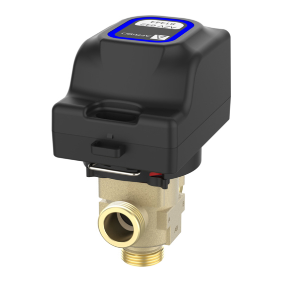
- Page 10 Produktbeschreibung Übersicht A. Elektroantrieb B. Elektrischer Anschluss C. Federklammer D. Ventilkörper E. Anzeiger für die Durch- flussrichtung F. Sichtfenster für Anzeiger für Durchflussrichtung - Grün: Durchflussrich- tung offen - Rot: Durchflussrichtung geschlossen Abbildung 2: Übersicht Varianten Ventilkörper 2-Wege (2-W) 3-Wege (3-W) 3-Wege-Eckventil (3-WE)
- Page 11 Produktbeschreibung Abmessungen Abbildung 3: Maße in mm Ventilkörper A Ruheposition 2-W NC 21,25 G¾ 10,0 Geschlossen 2-W NC 21,25 10,0 Geschlossen 2-W NO 21,25 G¾ 10,0 Offen 2-W NO 21,25 10,0 Offen 21,25 G¾ AB-B 21,25 AB-B 25,75 G1¼ 11,0 AB-B 3-WE 37,5...
- Page 12 Produktbeschreibung Lieferumfang Im Lieferumfang ist enthalten: 1. Zonenventil AZV (bestehend aus Elektroantrieb und Ventilkörper) 2. Netzkabel Zulassungsdokumente, Bescheinigungen, Erklärungen Das Produkt entspricht: • EMV-Richtlinie (2014/30/EU) • Niederspannungsrichtlinie (2014/35/EU) • RoHS-Richtlinie (2011/65/EU)
- Page 13 Produktbeschreibung Technische Daten 4.7.1 Elektroantrieb Parameter Wert Allgemeine Daten Abmessungen (B x H x T) 73 x 72 x 110 mm Werkstoff Gehäuse PC/ABS Umgebungsbedingungen Umgebungstemperatur Betrieb 0 ... 75 °C Umgebungstemperatur Lagerung -20 ... 65 °C Elektrische Daten Versorgungsspannung 230 V, 50 Hz Nennleistung 7 VA, in Ruheposition 0 VA...
- Page 14 Produktbeschreibung 4.7.2 Ventilkörper Parameter Wert Allgemeine Daten Werkstoff Gehäuse Messing CW617N Dichtungen EPDM (peroxidisch vernetzt) Anschlüsse G¾, G1, G1¼ Betriebsdruck 10 bar Maximal zulässiger Differenzdruck 2 bar Umgebungsbedingungen Umgebungstemperatur Betrieb 0 ... 75 °C Mediumstemperatur -15 ... 90 °C Interne Leckage Leckagefrei bis 1 bar Differenzdruck...
-
Page 15: Montage
Montage Montage WARNUNG HEISSE FLÜSSIGKEIT Wasser in Heizungsanlagen steht unter einem hohen Druck und kann Tempe- raturen bis über 100 °C erreichen. • Stellen Sie sicher, dass das Heizwasser abgekühlt ist, bevor Sie das Produkt montieren. Nichtbeachtung dieser Anweisung kann zu Tod, schweren Verletzungen oder Sachschäden führen. - Page 16 Montage Elektroantrieb demontieren 1. Ziehen Sie die Feder- klammer heraus. 2. Nehmen Sie den Elektro- antrieb vom Ventilkörper Abbildung 4: Demontage Elektroantrieb Ventilkörper montieren 1. Montieren Sie den Ventilkörper. - Beachten Sie die Durchflussrichtung siehe “Durchflussrichtung” auf Seite 16. 2. Montieren Sie den Elektroantrieb auf den Ventilkörper. 3.
- Page 17 Montage 5.2.1 Durchflussrichtung Durchflussrichtung Durchflussrichtung in geschaltet Ruheposition 2-Wege NC 2-Wege NO 3-Wege...
- Page 18 Montage Wechsel der Ruheposition Die Durchflussrichtung des Ventilkörpers in Ruheposition kann ohne Öffnen des Wasserkreislaufs geändert werden. Abbildung 5: Wechsel der Durchflussrichtung am Beispiel von AB-A auf AB-B...
- Page 19 Montage Elektrischer Anschluss GEFAHR ELEKTRISCHER SCHLAG • Stellen Sie sicher, dass durch die Art der elektrischen Installation der Schutz gegen elektrischen Schlag (Schutzklasse, Schutzisolierung) nicht vermin- dert wird. Nichtbeachtung dieser Anweisungen führt zu Tod oder schweren Verlet- zungen. GEFAHR ELEKTRISCHER SCHLAG DURCH SPANNUNGSFÜHRENDE TEILE •...
- Page 20 Montage 5.4.1 Steckerbelegung A. Geschaltete Versorgungsspannung schwarz (L2) - Schalteingang 0 V = Ruheposition - Schalteingang 230 V = Schaltstellung B. Neutralleiter blau (N) C. Dauerhafte Versorgungsspannung braun (L1) - 230 V...
-
Page 21: Wartung
Fehlerbehebung Elektroantrieb funktio- Keine Versorgungs- Stellen Sie die Versor- niert nicht spannung gungsspannung her Elektroantrieb defekt Bitte wenden Sie sich an die AFRISO-Service Hotline Falsche Durchflussrich- Ventilkörper falsch Siehe “Wechsel der tung herum eingebaut Ruheposition” auf Seite 17 Sonstige Störungen... -
Page 22: Gewährleistung
Gewährleistung Gewährleistung Informationen zur Gewährleistung finden Sie in unseren Allgemeinen Geschäftsbedingungen im Internet unter www.afriso.com oder in Ihrem Kauf- vertrag. Ersatzteile und Zubehör HINWEIS UNGEEIGNETE TEILE • Verwenden Sie nur Original Ersatz- und Zubehörteile des Herstellers. Nichtbeachtung dieser Anweisung kann zu Sachschäden führen. - Page 23 Anhang Anhang 12.1 EU-Konformitätserklärung...
-
Page 24: Zone Valve
Operating instructions Zone valve Copyright 2024 AFRISO-EURO-INDEX GmbH. All rights reserved. Version: 02.2024.0 ID: 900.000.1079... - Page 25 About these operating instructions About these operating instructions These operating instructions describe the zone valve "AZV" (also referred to as "product" in these operating instructions). These operating instructions are part of the product. • You may only use the product if you have fully read and understood these operating instructions.
- Page 26 Information on safety Information on safety Safety messages and hazard categories These operating instructions contain safety messages to alert you to poten- tial hazards and risks. In addition to the instructions provided in these oper- ating instructions, you must comply with all directives, standards and safety regulations applicable at the installation site of the product.
-
Page 27: Information On Safety
Information on safety Intended use This product may only be for installation in cooling and heating systems; it is used for: • Opening, closing and switching of media-carrying lines in refrigeration and heating technology in buildings The product may only be used for the following media: •... -
Page 28: Predictable Incorrect Application
Information on safety Predictable incorrect application The product must never be used in the following cases and for the following purposes: • Drinking water • Hazardous area - If the product is operated in hazardous areas, sparks may cause defla- grations, fires or explosions. -
Page 29: Transport And Storage
Transport and storage Transport and storage The product may be damaged as a result of improper transport or storage. NOTICE INCORRECT HANDLING • Verify compliance with the specified ambient conditions during transport or storage of the product. • Use the original packaging when transporting the product. •... - Page 30 Product description Product description The product consists of an electrical drive and a valve body. The valve body contains a ball valve that controls the flow of the medium in a cooling or heat- ing system. Product identification (nameplate) The nameplate is used to identify the product. The nameplate shows the fol- lowing data: A.
-
Page 31: Product Description
Product description Overview A. Electrical drive B. Electrical connection C. Spring clip D. Valve body E. Flow direction indicator F. Viewing window for flow direction indicator - Green: Direction of flow open - Red: Direction of flow closed Fig. 2: Overview Versions of valve body 2-way (2-W) 3-way (3-W) - Page 32 Product description Dimensions Fig. 3: Dimensions in mm Valve body Rest position 2-W NC 21.25 G¾ 10,0 closed 2-W NC 21.25 10,0 closed 2-W NO 21.25 G¾ 10,0 open 2-W NO 21.25 10,0 open 21.25 G¾ AB-B 21.25 AB-B 25.75 G1¼...
- Page 33 Product description Scope of delivery Scope of delivery: 1. Zone valve AZV (consisting of electrical drive and valve body) 2. Mains cable Approvals, conformities, certifications The product complies with: • EMC Directive (2014/30/EU) • Low Voltage Directive (2014/35/EU) • RoHS Directive (2011/65/EU)
- Page 34 Product description Technical specifications 4.7.1 Electrical drive Parameter Value General specifications Dimensions (W x H x D) 73 x 72 x 110 mm Housing material PC/ABS Ambient conditions Ambient temperature operation 0 ... 75 °C Ambient temperature storage -20 ... 65 °C Electrical data Supply voltage 230 V, 50 Hz...
- Page 35 Product description 4.7.2 Valve body Parameter Value General specifications Housing material Brass CW617N Seals EPDM (peroxide-crosslinked) Connections G¾, G1, G1¼ Operating pressure 10 bar Maximum permissible differential 2 bar pressure Ambient conditions Ambient temperature operation 0 ... 60 °C Temperature of the medium -15 ...
- Page 36 Mounting Mounting WARNING HOT LIQUID Water in heating systems is under high pressure and can have temperatures of more than 100 °C. • Verify that the heating water has cooled down before mounting the product. Failure to follow these instructions can result in death, serious injury or equipment damage.
- Page 37 Mounting Dismounting the electrical drive 1. Pull out the spring clip. 2. Remove the electrical drive from the valve body. Fig. 4: Dismounting of electrical drive Mounting the valve body 1. Mount the valve body. - Verify correct direction of flow See "Direction of flow" on page 15. 2.
- Page 38 Mounting Direction of flow Direction of flow switched Direction of flow in rest position 2-way NC 2-way NO 3-way...
- Page 39 Mounting Change of rest position The direction of flow of the valve body in the rest position can be changed without the necessity to open the water circuit. Fig. 5: Change of the direction of flow, example AB-A to AB-B...
- Page 40 Mounting Electrical connection DANGER ELECTRIC SHOCK • Verify that the degree of protection against electric shock (protection class, double insulation) is not reduced by the type of electrical installation. Failure to follow these instructions will result in death or serious injury. DANGER ELECTRIC SHOCK CAUSED BY LIVE PARTS •...
-
Page 41: Connector Assignment
Mounting 5.5.1 Connector assignment A. Switched supply voltage black (L2) - Switching input 0 V = rest position - Switching input 230 V = switching position B. Neutral conductor blue (N) C. Permanent supply voltage brown (L1) - 230 V... -
Page 42: Troubleshooting
2. Dismount the product (See "Mounting" on page 13., reverse sequence of steps). 3. Dispose of the product. Returning the device Get in touch with us before returning your product (service@afriso.de). Warranty See our terms and conditions at www.afriso.com or your purchase contract for information on warranty. -
Page 43: Spare Parts And Accessories
Only use genuine spare parts and accessories provided by the manufac- turer. Failure to follow these instructions can result in equipment damage. Product Product designation Part no. Zone valve AZV 2-W G¾ NC 81440 Zone valve AZV 2-W G1 NC 81441 Zone valve AZV 2-W G¾ NC 81442... - Page 44 Appendix Appendix 12.1 EU Declaration of Conformity...
- Page 45 Notice technique Vanne de zone Copyright 2024 AFRISO-EURO-INDEX GmbH. Tous droits réservés. Version: 02.2024.0 ID: 900.000.1079...
- Page 46 La présente notice technique La présente notice technique Cette notice technique contient la description de la vanne de zone "AZV" (dénommé ci-après "produit"). Cette notice technique fait partie du produit. • Utilisez le produit seulement après que vous aurez lu et compris intégra- lement la notice technique.
-
Page 47: Informations Sur La Sécurité
Informations sur la sécurité Informations sur la sécurité Consignes de sécurité et classes de risques Cette notice technique contient des consignes de sécurité destinées à attirer l'attention sur les dangers et les risques. Outre les instructions contenues dans cette notice technique, il faut vous assurer de l'observation de tous les règlements, normes et consignes de sécurité... - Page 48 Informations sur la sécurité Ce pictogramme avertit d'une tension électrique dange- reuse. Si ce pictogramme s'affiche dans une consigne de sécurité, il y a un risque de choc électrique. Usage normal Ce produit est destiné exclusivement à l'installation dans les installations de refroidissement et de chauffage ;...
-
Page 49: Équipement De Protection Individuelle
Informations sur la sécurité Utilisation non conforme prévisible Le produit ne doit, en particulier, pas être utilisé dans les cas suivants : • Eau potable • Dans des zones à risque d'explosion - En cas de service dans des zones à risque d'explosion, des étincelles peuvent provoquer des déflagrations, des incendies ou des explosions. -
Page 50: Transport Et Stockage
Transport et stockage Transport et stockage Un transport et un stockage inadéquats risquent de causer des dommages au produit. AVIS MANUTENTION INAPPROPRIÉE • Assurez-vous que les conditions ambiantes spécifiées sont respectées pen- dant le transport et le stockage. • Utilisez l'emballage d'origine pour le transport. •... - Page 51 Description du produit Description du produit Le produit se compose d'un entraînement électrique et d'un corps de vanne. Dans le corps de la vanne se trouve une vanne à bille qui commande le débit du fluide dans une installation de refroidissement ou de chauffage. Identification du produit (plaque signalétique) La plaque signalétique permet d'identifier le produit.
-
Page 52: Description Du Produit
Description du produit Aperçu A. Entraînement électrique B. Branchement électrique C. Clip D. Corps de vanne E. Indicateur de sens d'écou- lement F. Fenêtre de visualisation pour l'indicateur de sens d'écoulement - Vert : Sens d'écoule- ment fermé - Rouge : Sens d'écoule- ment fermé... - Page 53 Description du produit Dimensions Figure 3: Dimensions en mm Corps de Position de vanne repos 2-W NC 21,25 G¾ 10,0 fermée 2-W NC 21,25 10,0 fermée 2-W NO 21,25 G¾ 10,0 ouverte 2-W NO 21,25 10,0 ouverte 21,25 G¾ AB-B 21,25 AB-B 25,75...
-
Page 54: Composants Fournis
Description du produit Composants fournis Composants fournis : 1. Vanne de zone AZV (composée d'un entraînement électrique et d'un corps de vanne) 2. Câble secteur au secteur Agréments, certificats, déclarations Le produit est conforme à : • Directive CEM (2014/30/UE) •... - Page 55 Description du produit Caractéristiques techniques 4.7.1 Entraînement électrique Paramètre Valeur Caractéristiques générales Dimensions (L x H x P) 73 x 72 x 110 mm Matériau du boîtier PC/ABS Conditions ambiantes Température ambiante service 0 ... 75 °C Température ambiante stockage -20 ...
- Page 56 Description du produit 4.7.2 Corps de vanne Paramètre Valeur Caractéristiques générales Matériau du boîtier Laiton CW617N Joints EPDM (réticulation au peroxyde) Raccordements G¾, G1, G1¼ Pression de service 10 bars Pression différentielle maximale 2 bars admissible Conditions ambiantes Température ambiante service 0 ...
-
Page 57: Montage
Montage Montage AVERTISSEMENT LIQUIDE CHAUD L'eau dans les installations de chauffage est sous haute pression et peut atteindre des températures dépassant 100 °C. • Assurez-vous que l'eau de circuit de chauffage a suffisamment refroidi avant de monter le produit. La non-observation de ces instructions peut entraîner la mort ou des bles- sures graves ou un dommage matériel. - Page 58 Montage Montage de l'entraînement électrique 1. Retirez le clip. 2. Retirez l'entraînement électrique du corps de la vanne. Figure 4: Démontage entraînement électrique Montage du corps de vanne 1. Montez le corps de vanne. - Assurez-vous que le sens d'écoulement est correct Voir "Sens de pas- sage", page 15.
- Page 59 Montage Sens de passage Sens d'écoulement com- Sens d'écoulement en posi- muté tion de repos 2-voies NC 2-voies NO 3-voies...
- Page 60 Montage Changement de position de repos Le sens d'écoulement du corps de la vanne en position de repos peut être modifié sans qu'il soit nécessaire d'ouvrir le circuit d'eau. Figure 5: Changement du sens d'écoulement, exemple AB-A sur AB-B...
-
Page 61: Branchement Électrique
Montage Branchement électrique DANGER CHOC ÉLECTRIQUE • Assurez-vous que le degré de protection contre les chocs électriques (classe de protection, isolation double) ne soit pas réduit par le type de l'installation électrique. La non-observation de ces instructions entraîne la mort ou des blessures graves. - Page 62 Montage 5.5.1 Affectation de connecteur A. Tension d'alimentation commutée noire (L2) - Entrée de commutation 0 V = position de repos - Entrée de commutation 230 V = position de commutation B. Conducteur de neutre bleu (N) C. Tension d'alimentation permanente brun (L1) - 230 V...
-
Page 63: Suppression Des Dérangements
Entraînement électrique Aucune tension d'ali- Établissez la tension ne marche pas mentation d'alimentation Entraînement électrique Veuillez contacter défectueux l'AFRISO Service Hot- line Sens d'écoulement Corps de vanne monté Voir "Changement de incorrect à l'envers position de repos", page 16. Autre dérangement... -
Page 64: Garantie
Garantie Garantie Les informations sur la garantie figurent dans nos "Conditions générales de vente" sur le site www.afriso.com ou dans votre contrat d'achat. Pièces détachées et accessoires AVIS PIÈCES INADAPTÉES • N'utilisez que des accessoires et des pièces détachées d'origine provenant du fabricant. - Page 65 Annexe Annexe 12.1 Déclaration de conformité UE...
Need help?
Do you have a question about the AZV and is the answer not in the manual?
Questions and answers