Table of Contents
Advertisement
Quick Links
Advertisement
Table of Contents

Related Manuals for PowMr POW-SunSmart LVM8K


Summary of Contents for PowMr POW-SunSmart LVM8K
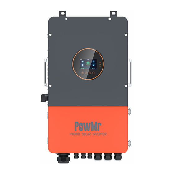
- Page 1 User Manual POW-SunSmart LVM12K...
-
Page 2: Important Safety Instructions
User Manual POW-SunSmart LVM12K Important Safety Instructions Please keep the user manual properly for future reference! Warning: It is essential to read, understand, and adhere to all safety instructions provided in this document. Failure to comply with safety regulations may result in property damage or personal injury. - Page 3 User Manual POW-SunSmart LVM12K consult with the battery manufacturer's relevant literature to ascertain the compatibility of this product with the battery. Always adhere to the safety instructions provided by the battery manufacturer. 2. This is a safety-class product equipped with a protective grounding terminal. Continuous protective grounding must be provided by the AC input/output terminals.
-
Page 4: Table Of Contents
User Manual POW-SunSmart LVM12K Table of Contents Important Safety Instructions ......................1 1 About This Manual ..........................3 1.1 Scope ................................. 3 1.2 Target Audience............................3 1.3 Manual Usage ............................3 2 Product Overview ..........................4 2.1 Features ..............................4 2.2 System Connection Diagram ....................... - Page 5 User Manual POW-SunSmart LVM12K 5.6 Battery Parameters..........................40 6 Communication ..........................42 6.1 Overview ..............................42 6.2 USB-B Port ............................. 42 6.3 WIFI Port ..............................43 6.4 RS485 Port .............................. 43 6.5 CAN Port ..............................44 6.6 External CT Port ............................ 44 6.7 Dry Contact ............................
-
Page 6: About This Manual
1. Before using the product, carefully review this user manual and keep it stored in an easily accessible location. 2. All information in the user manual, including images and symbols, is the property of PowMr. Unauthorized use of any portion or all of the content is prohibited for individuals outside the company. -
Page 7: Product Overview
User Manual POW-SunSmart LVM12K 2 Product Overview POW-SunSmart series is a new type of solar energy storage inverter control inverter integrating solar energy storage & utility charging and energy storage, AC sine wave output. It adopts DSP control and features high response speed, reliability, and industrial standard through an advanced control algorithm. - Page 8 User Manual POW-SunSmart LVM12K ⚫ Energy saving mode function to reduce no-load energy losses. ⚫ With two output modes of utility bypass and inverter output, with uninterrupted power supply function ⚫ LCD large screen dynamic flow diagram design, easy to understand the system data and operation status.
-
Page 9: System Connection Diagram
User Manual POW-SunSmart LVM12K 2.2 System Connection Diagram The diagram below shows the system application scenario of this product. A complete system consists of the following components: 1. PV modules: converts light energy into DC energy, which can be used to charge the battery via an inverter or directly inverted into AC power to supply the load. -
Page 10: Production Overview
User Manual POW-SunSmart LVM12K 2.3 Production Overview LED Indicators Load Ground Terminal LCD Screen Grid Input Ground Terminal Touchable Keys Transmitter-PLC WIFI Port AFCI RS485 Port Parallel Port A External CT Port Parallel Port B CAN Port Dry Contact PV1 Terminals USB-B Port PV2 Terminals Battery Terminal... -
Page 11: Dimension Drawing
User Manual POW-SunSmart LVM12K 2.4 Dimension Drawing... -
Page 12: Installation
User Manual POW-SunSmart LVM12K 3 Installation 3.1 Select the Mount Location POW-SunSmart series can be used outdoors (protection class IP65). Please consider the followings before selecting the location. ⚫ Choose the solid wall to install the inverter. ⚫ Mount the inverter at eye level. ⚫... -
Page 13: Mount The Inverter
User Manual POW-SunSmart LVM12K 3.2 Mount the Inverter Drill four mounting holes in the wall with an electric drill according to the specified dimensions. Then insert four M8*60 expansion bolts into the holes. 3.3 Remove the Terminal Cover & Anti Insect Net Using a screwdriver, remove the fan shroud and open the cover. -
Page 14: Connection
4 Connection 4.1 Split-Phase Mode AC Output 120V 240V 120V Items Description POW-SunSmart LVM8K; POW-SunSmart LVM10K; Applicable Model POW-SunSmart LVM12K Output Voltage Range (L-N) 100~120Vac, 120Vac (default) Output Voltage Range (L1-L2) 200~240Vac, 240Vac (default) 4.2 Cable & Circuit Breaker Requirement ⚫... - Page 15 User Manual POW-SunSmart LVM12K ⚫ AC INPUT Model Schema Cable Diameter Circuit Breaker Spec 13mm² / 6AWG 8KW Model 3P-63A (L1/L2/N) 13mm² / 6AWG 10KW Model 3P-63A (L1/L2/N) 13mm² / 6AWG 12KW Model 3P-63A (L1/L2/N) ⚫ GENERATOR INPUT Model Schema Cable Diameter Circuit Breaker Spec 13mm²...
-
Page 16: Grid & Load & Gen Connection
User Manual POW-SunSmart LVM12K NOTICE ⚫ PV INPUT, AC INPUT, AC OUTPUT, GENERATOR INPUT 1. Use a stripper to remove the 6~8mm insulation of the cable. 2. Fixing a ferrule at the end of the cable. (ferrule needs to be prepared by the user) ⚫... -
Page 17: Battery Connection
User Manual POW-SunSmart LVM12K DANGER ⚫ Before connecting AC inputs and outputs, the circuit breaker must be opened to avoid the risk of electric shock and must not be operated with electricity. ⚫ Please check that the cable used is sufficient for the requirements, too thin, poor quality cables are a serious safety hazard. -
Page 18: Pv Connection
User Manual POW-SunSmart LVM12K 4.5 PV Connection Connect the positive and negative wires of both PVs in the cable locations and sequence shown in the diagram below. The positive wire runs through the AFCI unit. DANGER ⚫ Before connecting PV, the circuit breaker must be opened to avoid the risk of electric shock and must not be operated with electricity. -
Page 19: Dry Contact Connection
User Manual POW-SunSmart LVM12K 4.6 Dry Contact Connection Use a small screwdriver to push back the direction indicated by the arrow, then insert the communication cable into the dry contact port. (Communication cable diameter 0.2~1.5mm²) 4.7 Grounding Connection Please make sure the grounding terminal connect to the Grounding Busbar. NOTICE ⚫... -
Page 20: Inverter Start
User Manual POW-SunSmart LVM12K 4.8 Inverter Start After ensuring that the wiring is reliable and the wire sequence is correct, follow the power-on sequence below to start the inverter safely: Step1. Close the circuit breaker of the battery. Step2. Press the rocker switch on the bottom of inverter, the screen and indicators light up to indicate that the inverter has been activated. -
Page 21: Operation
User Manual POW-SunSmart LVM12K 5 Operation 5.1 Operation and Display Panel The operation and display panel below includes 1 LCD screen, 3 indicators, 4 touchable keys. LCD screen LED indicators Physical button ➢ Touchable Keys Touchable Keys Description Enter/exit the setting menu Go to the next selection Go to the previous selection Confirm/Enter the selection in setting menu... -
Page 22: Display Panel
User Manual POW-SunSmart LVM12K 5.2 Display Panel Icon Description Icon Description Solar panel Load Battery Grid Home page Inverter is working History data Setting Local time The buzzer is silent Indicators that machine is currently in energy-saving The energy direction mode. -
Page 23: View Real-Time Data
User Manual POW-SunSmart LVM12K 5.3 View Real-Time Data On the LCD home screen, click the inverter icon, battery icon, mains icon, load icon and photovoltaic icon to view the real-time data of the machine. System data Item Item Machine state SN code MCU1 version Minor version... - Page 24 User Manual POW-SunSmart LVM12K Load data L1 Voltage L2 Voltage L1 Current L2 Current L1 UPS load active power L2 UPS load active power L1 UPS load apparent power L2 UPS load apparent power Frequency Load rate L1 Home load power L2 Home load power PV data PV1 voltage V...
-
Page 25: Setting
User Manual POW-SunSmart LVM12K 5.4 Setting Operating instructions: Click on the settings in the menu bar at the bottom of the screen to enter the setup interface, including the basic settings, work mode settings, battery settings, grid settings, advanced settings of the five major setup items. 5.4.1 Basic Setup ➢... - Page 26 User Manual POW-SunSmart LVM12K ➢ Time Setup ➢ Password Setting Password is required to access the Grid Settings and Advanced Settings Default password is “00000” Password setting value range: 0-65535...
- Page 27 User Manual POW-SunSmart LVM12K 5.4.2 Work Mode Setup ➢ Work Mode Home Load: connected to the GRID port of the machine, requires external CT for monitoring. UPS Load: connected to the LOAD port of the machine. Parameter Meaning Option Description Direct grid connection of excess PV On grid energy.
- Page 28 User Manual POW-SunSmart LVM12K PV power supply logic: charge-load-grid First to charging connection PV power supply logic: load-grid First to grid connection-charge Grid charging enable Selectable grid participation in battery charging The battery does not discharge, and the Standby battery is discharged only when the working state is off the grid.
- Page 29 User Manual POW-SunSmart LVM12K ➢ Peak Shaving Parameter Meaning Description Time charging/ Select whether to turn on timed charging and discharging discharging enable Start/End Time Setting the time period for timed charging and discharging Setting the battery charging cut-off SOC value and the cut-off SOC Stop SOC value for discharging during the timed charging and discharging time period (during BMS communication)
- Page 30 User Manual POW-SunSmart LVM12K 5.4.3 Battery setup ➢ Battery Type Parameter Meaning Option Description Maximum battery charging current is limited according to the inverter battery charging current setting value. Battery chg. curr. limit (Valid for BMS Maximum battery charging current is limited by communication)...
- Page 31 When the BMS port selection setting item = 485 or CAN, you need to select the corresponding lithium battery manufacturer brand for communication: 1:PACE-PACEEX; 2:RUDA-Ritar; 3:AOGUAN-ALLGRAND BATTERY BMS comm. protocol 4:OULITE-OLITER; 5:CEF-CHANGFENG TECHNOLOGY; 6:XINWANGDA -SUNWODA; 7:DAQIN -DAKING; 8:WOW-SRNE 9:PYL-PYLONTECH; 10:MIT-FOXESS; 11:XIX-XYE; 12:POL-POWMR; 13:GUOX-Gotion; 14:SMK-SMK; 15:VOL-WEILAN; 16:UZE-YUZE...
- Page 32 User Manual POW-SunSmart LVM12K ➢ Battery Manage Parameter Meaning Description When the battery is charging, the voltage reaches the value to Maximum chg. voltage stop charging. When the battery is fully charged, the inverter stops charging Batt. Recharging voltage and resumes charging when the battery voltage falls below this voltage value.
- Page 33 User Manual POW-SunSmart LVM12K When the battery report voltage low fault, the battery voltage Batt volt low fault recovery reach this setting, the fault will be cleared. When the battery voltage reach this setting, the inverter will Batt voltage low fault report battery voltage low fault.
- Page 34 User Manual POW-SunSmart LVM12K 5.4.4 On grid setup To enter this setting, you need to enter the password set by the user, the default password is “00000”. ➢ Basic Parameter Meaning Description USA: IEEE Std1547-2018/IEEE1547.1-2020 California: RULE21 Hawaii: HECO Grid Standard Puerto Rico Columbia: UL1741 Other regions: GNL...
- Page 35 User Manual POW-SunSmart LVM12K Error calibration power in the case of backflow prevention, Zero-export power recommended setting 20-100W. On-Grid Reactive Power Setting range 0-100%, % of reactive power Reactive power over/under Over indicates 0%-100% / Under indicates -100%-0% excited On Grid PF Setting range 0.8-1 Power factor over/under Over indicates 0.8-1 / Under indicates -0.8 - -1...
- Page 36 User Manual POW-SunSmart LVM12K ➢ Enter Service (This setting is not recommended to be changed by the customer) Parameter Meaning Description Enter service enable Grid-connect enable setting (on by default) Connect Voltage Low Grid-connected low voltage protection voltage Connect Frequency Low Grid-connected low-frequency protection points Connect Voltage High Grid-connected high-voltage protection voltage...
- Page 37 User Manual POW-SunSmart LVM12K ➢ Grid Protection (This setting is not recommended to be changed by the customer) Parameter Meaning Description Class 1 undervoltage protection point Class 1 underfrequency protection point Class 2 undervoltage protection point Class 2 underfrequency protection point Class 3 undervoltage protection point Class 1 overvoltage protection point Class 1 overfrequency protection point...
- Page 38 User Manual POW-SunSmart LVM12K ➢ Other Parameter Meaning Description Frequency Droop(F-P) Adjustment of inverter output power according to grid enable frequency Adjustment of the inverter active power according to the set Volt -Watt (V-P) curve enable grid voltage Adjustment of the inverter reactive power according to the Volt-Var (V-Q) curve enable set grid voltage Adjustment of the inverter reactive power according to the...
- Page 39 User Manual POW-SunSmart LVM12K 5.4.5 Advance Setup To enter this setting, you need to enter the password set by the user, the default password is “00000”. ➢ Generator Parameter Meaning Description Maximum battery charging current during generator Max charging current by gen. charging Setting the power of the generator up to the rated power of Generator rate power...
- Page 40 User Manual POW-SunSmart LVM12K ➢ Other Parameter Meaning Description PE-N connect enable Enable automatic switching of PE-N connections PV Riso check enable Enable PV insulation impedance detection AFCI check enable Turn on AFCI check Leakage curr. protection Enable leakage current protection enable After turning on, the inverter output turns off when the BMS comm.
- Page 41 User Manual POW-SunSmart LVM12K ➢ Restart Inverter Parameter Meaning Description Restore to factory setting Reset all inverter settings to factory setting Restart Inverter Restart the inverter...
-
Page 42: Time-Slot Charging/Discharging Function
User Manual POW-SunSmart LVM12K 5.5 Time-Slot Charging/Discharging Function The POW-SunSmart series is equipped with a time-slot charging and discharging function, which allows users to set different charging and discharging periods according to the local peak and valley tariffs, so that the utility power and PV energy can be used rationally. When the utility price is expensive, the battery inverter can be used to supply power to the load;... -
Page 43: Battery Parameters
User Manual POW-SunSmart LVM12K 5.6 Battery Parameters ➢ Lead-acid battery Sealed lead Gel lead acid Flooded lead User- Battery type acid battery battery acid battery defined Parameter USER Overdisconnect Voltage 40~60V Boost charging voltage 57.6V 56.8V 57.6V (can be set) Undervoltage alarm 40~60V voltage... - Page 44 User Manual POW-SunSmart LVM12K ➢ Li-ion battery User- Ternary Battery type defined Parameter USER Overdisconnect Voltage 40~60V Boost charging voltage 53.2V 57.6V 56.8V 53.2V 49.2V (can be set) Undervoltage alarm 40~60V 43.6V 46.8V 49.6V 46.4V 43.2V voltage (can be set) Undervoltage 40~60V 38.8V...
-
Page 45: Communication
User Manual POW-SunSmart LVM12K 6 Communication 6.1 Overview WIFI port CAN port Dry contact RS485 port Parallel port A USB-B port External CT port Parallel port B USB-A port 6.2 USB-B Port USB typeB USB2.0 printer The user can read and modify device parameters through this port by using the host software. Please contact us for the host software installation package if you require one. -
Page 46: Wifi Port
User Manual POW-SunSmart LVM12K 6.3 WIFI Port The WIFI port is used to connect to the Wi-Fi/GPRS data acquisition module, which allows users to view the operating status and parameters of the inverter through the cell phone APP. RJ45 Definition Pin 1 Pin 2 Pin 3... -
Page 47: Can Port
User Manual POW-SunSmart LVM12K 6.5 CAN Port The CAN port is used to connect to the BMS of Li-ion battery. RJ45 Definition Pin 1 Pin 2 Pin 3 Pin 4 CANH Pin 5 CANL Pin 6 Pin 7 Pin 8 NOTICE ⚫... -
Page 48: Dry Contact
User Manual POW-SunSmart LVM12K 3. Current transformer (CT) dimensions: (mm) laser engraving fuse side 6.7 Dry Contact Dry contact port with 3 functions: 1. RSD power supply 2. Temperature sampling (reserved) 3. Generator remote start/stop Function Description RSD power supply PIN 1 is GND,PIN 2 is RSD 12V+ Temperature sampling Pin 1 &... - Page 49 User Manual POW-SunSmart LVM12K 3. When connected to the BMS, the generator will be remotely started when the battery SOC is lower than the set point for switching to grid SOC. 4. When there is no BMS connection, the generator will be remotely stopped when the battery voltage reaches the voltage threshold for switching from grid to battery, or when the battery is fully charged.
-
Page 50: Fault And Remedy
User Manual POW-SunSmart LVM12K 7 Fault and Remedy 7.1 Fault Code Fault Does it Affect Fault name Description code the outputs BatVoltLow Battery undervoltage alarm Battery discharge average current BatOverCurrSw over-current (software protection). BatOpen Battery not-connected alarm Battery undervoltage stop discharging BatLowEod alarm Battery overcurrent (hardware... - Page 51 User Manual POW-SunSmart LVM12K chip InvShort Inverter short-circuit protection Bussoftfailed Busbar soft start failure MPPT heat sink over-temperature OverTemperMppt protection Inverter AC output with load or AC OverTemperInv charging radiator over-temperature protection. FanFail Fan blockage or failure fault EEPROM Memory failure ModelNumErr Model setting error Positive and negative bus voltage...
- Page 52 User Manual POW-SunSmart LVM12K ParaShareCurrErr Parallel current sharing fault Large battery voltage difference in ParaBattVoltDiff parallel mode Inconsistent mains input source in ParaAcSrcDiff parallel mode Hardware synchronization signal error ParaHwSynErr in parallel mode InvDcVoltErr Inverter DC voltage error Inconsistent system firmware version in SysFwVersionDiff parallel mode Parallel line connection error in parallel...
- Page 53 User Manual POW-SunSmart LVM12K BMSUnderTem BMS alarm battery low temperature. BMS alarm battery over-temperature. BMSOverTem (Effective after successful BMS communication) BMS alarm battery over-current. BMSOverCur (Effective after successful BMS communication) BMS alarm low battery. (Effective after BMSUnderVolt successful BMS communication)
-
Page 54: Troubleshooting
User Manual POW-SunSmart LVM12K 7.2 Troubleshooting Fault code Faults Remedy Check if the battery switch or PV switch is closed; whether the switch is in the "ON" state; press any Display No display on the screen button on the screen to exit the screen sleep mode. - Page 55 User Manual POW-SunSmart LVM12K Check if the parallel line is not connected well, [40] [43] Parallel connection fault such as loose or wrong connection. Check whether the setting of parallel ID number [35] Parallel ID setting error is repeated. Check if the parallel current sharing line is not [37] Parallel ID setting error connected...
- Page 56 User Manual POW-SunSmart LVM12K Power down and restart the device, if it continues Grid-connected current [54] to report faults, contact the manufacturer after with DC component over sales. [55] Grid standard not set Setting standards for grid integration Low insulation resistance Check that the system is well grounded and that [56] fault...
-
Page 57: Protection And Maintenance
User Manual POW-SunSmart LVM12K 8 Protection and Maintenance 8.1 Protection Features Protection Feature Instruction When the charge current or power of the configured PV array PV current-limiting exceeds the rated current and power of the inverter, it will protection charge at the rated current and power. If the PV voltage exceeds the maximum value allowed by the PV input over- hardware, the machine will report a fault and stop the PV... - Page 58 User Manual POW-SunSmart LVM12K immediately, and then manually re-powered and turned on before normal output can be restored. (Non-utility bypass condition) When the internal temperature of the inverter is too high, the Heat sink over- inverter will stop charging and discharging; when the temperature temperature returns to normal, the inverter will resume protection...
-
Page 59: Maintenance
User Manual POW-SunSmart LVM12K 8.2 Maintenance To maintain optimum and long-lasting working performance, we recommend that the following items are checked twice a year. 1. Ensure that the airflow around the inverter is not blocked and remove any dirt or debris from the radiator. -
Page 60: Parameter Table
User Manual POW-SunSmart LVM12K 9 Parameter Table POW- POW- POW- Model SunSmart SunSmart SunSmart Settable LVM8K LVM10K LVM12K Inverter Output @240V 12000W Rated Output Power 8800W 10000W @208V 10400W Max. Peak Power 2 times rated power Rated Output Voltage 120/240Vac (Split-phase); 120/208V (Three-phase) √... - Page 61 User Manual POW-SunSmart LVM12K Max. PV Array Power 5500W/5500W 5500W/5500W 6600W/6600W Max. Input Current 25A/25A Max. Voltage of Open 550Vdc/550Vdc Circuit MPPT Voltage Range 125-450Vdc/125-450Vdc Grid / Generator input Input Voltage Range 90-140Vac Frequency Range 50/60Hz Bypass Phase Current Efficiency MPPT Tracking Efficiency 99.9% Max Efficiency...
-
Page 62: Appendix: Parallel Connection
User Manual POW-SunSmart LVM12K 10 Appendix: Parallel Connection 10.1 Parallel Operation 1. Up to six units connected in parallel. 2. When using the parallel operation function, the following connecting lines (package accessories) shall be firmly and reliably connected. Parallel communication line* 1 10.2 Precautions for Connecting the Parallel Connecting Lines Warning: 1. - Page 63 User Manual POW-SunSmart LVM12K connected together, but the L lines of AC outputs of different phases cannot be connected together. Other precautions are the same as single-phase connection of parallel machines. 4. GRID wiring: Parallel connection in single phase: ensure L-to-L, N-to-N and PE-to-PE connection for all solar storage inverters, and that the connection is correct with the same wiring length and line diameter before power on, so as to avoid the abnormal operation of parallel system output caused by wrong connection.
-
Page 64: Split-Phase Parallel Connection
User Manual POW-SunSmart LVM12K 10.3 Split-Phase Parallel Connection Setting for each inverter: Select "Parallel" for parallel mode, select "Split Phase" for grid type, when "120V" is selected for output phase voltage, the output L1-L2 voltage is 240V, L1-N voltage is 120V, L2-N voltage is 120V. - Page 65 User Manual POW-SunSmart LVM12K 2. Three inverters in parallel: 3. Four inverters in parallel:...
- Page 66 User Manual POW-SunSmart LVM12K 4. Five inverters in parallel: 5. Six inverters in parallel:...
-
Page 67: Three-Phase Parallel Connection
User Manual POW-SunSmart LVM12K 10.4 Three-Phase Parallel Connection (1) 2 inverters connected in parallel to form a three-phase output (three-phase unbalanced) P1 machine setting: Parallel mode select "Three phase A", grid type select "Three Phase", when output phase voltage select "120V, the output L1-L2 voltage is 208V, L1-N voltage is 120V, L2-N voltage is 120V. - Page 68 User Manual POW-SunSmart LVM12K (2) 3 or 6 inverters in parallel to form a three-phase output (three-phase balanced) P1 machine setting: Parallel mode select "Three phase A", grid type select "Three Phase", when output phase voltage select "120V, the output L1-L2 voltage is 208V, L1-N voltage is 120V, L2-N voltage is 120V.
- Page 69 User Manual POW-SunSmart LVM12K P2 machine setting: Parallel mode select "Three phase B", grid type select "Three Phase", when output phase voltage select "120V, the output L1-L2 voltage is 208V, L1-N voltage is 120V, L2-N voltage is 120V. P3 machine setting: Parallel mode select "Three phase C", grid type select "Three Phase", when output phase voltage select "120V, the output L1-L2 voltage is 208V, L1-N voltage is 120V, L2-N voltage is 120V.
- Page 70 User Manual POW-SunSmart LVM12K...
- Page 71 User Manual POW-SunSmart LVM12K...
Need help?
Do you have a question about the POW-SunSmart LVM8K and is the answer not in the manual?
Questions and answers