Advertisement
Quick Links
Advertisement

Related Manuals for LEGACY AVIATION EXYTEME FLIGHT TURBO BUSHMASTER


Summary of Contents for LEGACY AVIATION EXYTEME FLIGHT TURBO BUSHMASTER
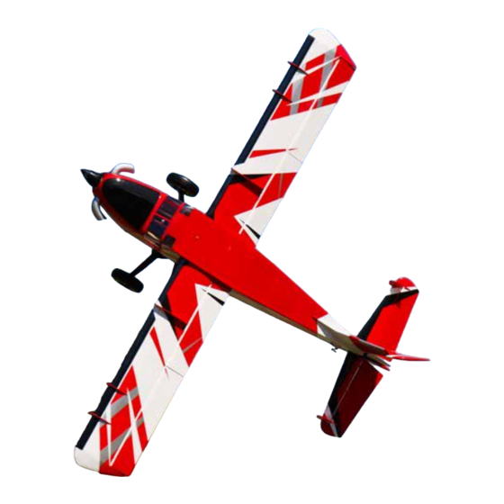
- Page 1 84in/2.1M 84in/2.1M 6S 3000-5000mah 7.5-8.5 lbs / 3.4-3.9 kg...
- Page 2 Please read the following paragraphs before beginning assembly of your aircraft! THIS IS NOT A TOY! Serious injury, destruction of property, or even death may result from the misuse of this product. Extreme Flight RC is providing you, the consumer with a very high quality model aircraft component kit, from which you, the consumer, will assemble a flying model.
- Page 3 Attach the landing gear to the fuselage with the 4 included screws and washers. Use blue loctite thread locking compound on these screws. Test fit the fiberglass landing gear fairings, and mark the location onto the landing gear. Sand the area and apply “Goop” or other rubberized adhesive and install the fairing. Apply tape and allow to dry.
- Page 4 Using the washer and locking nut, attach the axle to the landing gear. We recommend to grind small flat areas into the axle as shown to help the set screws in the wheel collars to grip the axle better. In- stall one collar (using loctite on the set screw), then the wheel, then the second collar.
- Page 5 Locate the tailwheel pushrod, packed in the wing bag. Push the pushrod through its guide tube to cre- ate a dimple in the covering and cut the covering so the pushrod emerges from the fuselage as shown. Attach the tailwheel to the fuselage using the included screws and blue loctite. Screw the ball link con- nector onto the pushrod (here we use a cordless drill) and attach to the tailwheel tiller with 2mm screw and locknut.
- Page 6 The elevator inserts through the opening in the rear of the fuselage, upside down and back- wards, and then after it is centered, flip it over to the proper position. When you insert the elevator, one of the hinge points will be a tight fit. Don’t risk breaking this hinge point, instead trim off about 3/8”...
- Page 7 Use a tape measure to check the alignment of the horizontal stabiliser to the wing tube, and glue in place with thin CA. Clean up any CA drips with acetone. Use epoxy glue to install the hinges into the stabilizer, make sure the elevator moves freely. Allow to cure. The vertical stabilizer and rudder install with a carbon tube and 3mm screw.
- Page 8 Locate the hardware for the Stab and Rudder. Installing control horns: All of the control horns on your aircraft install in the same way. Locate the cor- rect control horn for each surface. Prep the horns by lightly scuffing the gluing area (the part which will go into the control surface) with sandpaper or an emery board.
- Page 9 Using epoxy glue, mount the stab fences to the ends of the horizontal stabilizer as shown. Optional Step: Included in your kit are two balsa pieces which can be used as fillers by installing with CA glue behind the elevator. To color match these panels, your kit includes spare covering sections, also useful for small repairs.
- Page 10 Tape the rudder as shown to hold it straight while you assemble the cables at the rear. Assemble the cable ends as shown onto the rudder horns. Pull the cables taut and through the crimp tubes and crimp as shown. Add a drop of thin CA to the crimp. Thread the cable ends into the ball links to tighten the cables as needed.
- Page 11 Mount your ESC as shown, tying all wires securely. Install the cowl and check the fit of the prop mount to make sure it extends a few mm beyond the front of the cowl. If you need extra motor extension, your kit includes motor mount spacers as shown. Locate the Main Wing hardware.
- Page 12 Locate the wing strut mounts and screws. Attach the strut mounts with loctite. Find the correct (Right or Left side) strut and attach to the strut mount with the long screw. Lock the screw with a drop of thin CA on the head. The strut is intended to fold against the wing as shown for storage.
- Page 13 Locate the lower strut mount inside the fuselage. This is where the struts are mounted for flight with a screw. The balance point for the maiden flight of the Bushmaster is on the wing spar tube, you can easily support the plane by the tube and it should hang level. Move your LiPo battery to adjust CG. Be sure to use adhesive velcro on your battery and battery tray AND a velcro strap around the battery and tray, to retain the battery in place.
- Page 14 Control settings: Elevator: Low Rate 8-10 deg. 15-20% expo 3D Rate 45 deg. 60-70% expo Aileron: Low Rate 15-20 deg. 20-30% expo High Rate 38-40 deg. 60-70% expo (For best roll rate, mix flaps to ailerons) Rudder: Low Rate 20 deg 40-45% expo High Rate 45 deg.
Need help?
Do you have a question about the EXYTEME FLIGHT TURBO BUSHMASTER and is the answer not in the manual?
Questions and answers