Advertisement
Quick Links
Advertisement

Related Manuals for LEGACY AVIATION FLOATS


Summary of Contents for LEGACY AVIATION FLOATS
- Page 1 FLOATS Assembly Guide...
-
Page 2: Required Tools And Materials
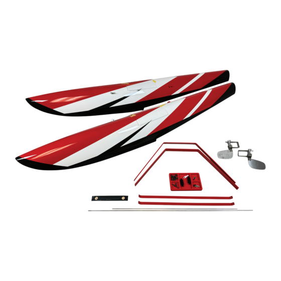
2 servo extensions, 12” for 84” size, 24” for larger sizes. Also note that if you wish to change back-and-forth between wheel and floats, you will want to arrange a plug, such as an MPX single, on the fuselage for easy attachment of the water servo connection. - Page 3 In this manual, we are using the 84” Bushmaster floats for the build sequence, but all of our floats assemble in fundamentally the same way. The primary differences you will notice in the larger float kits are more aluminum struts to form X-braces, necessary with the larger floats, and the water rudder servo is full size, versus the mini size used in the 84”.
- Page 4 The struts asemble with 3MM bolts. Look carefully to find which struts have female threads for the bolts to screw into. Use a drop of blue Loctite thread locker on each of these bolts. NOTE: Now is a conveneient time to run your servo extension wire into the float, if you use the nearest slot which the strut inserts into, you can insert the servo plug through the slot and only make a small clearance of the slot to accommodate the servo wire.
- Page 5 We intend for the floats to use ONE rudder servo and either ONE or TWO water rudders. For our personal aircraft, we prefer ONE water rudder. We find that in all but the highest wind condi- tions, one water rudder gives us plenty of directional control and results in a lighter, less compli- cated setup.
- Page 6 Then we remove the hatch, and apply a waterproofing bead of caulk or Gorilla CLEAR BOND glue as shown. Then install the hatch with screws.
- Page 7 The water rudders install onto the back of the floats with 3mm bolts. Place a drop of Blue Loctite threadlocker onto each screw, and use a little caulk/clear bond between the water rudder bracket and the float to seal against any possible leaks. If you use only one water rudder, seal these holes on the other float as well.
- Page 8 Drill the hole for the pushrod, expanding it to fit the rubber “bellows” pushrod seal as shown. Use caulk or CLEAR BOND to seal the joint to the float body. Install the push- rod. Here we have removed the water rudder for photo clarity.
- Page 9 This photo shows the proper installation of the water rudder, pushrod, and seal. On the interior end of the pushrod, install the ball link.
- Page 10 For the 84” size floats, the servo mount is sized for classic “mini” servos such as the Hitec HS- 5245MG. New “super mini” servos are much more powerful and able to handle the higher voltages more often used today. Mounting a more modern servo, such as the Savox SV1250MG, requires clearancing the mount as shown.
- Page 11 Clear Bond. Remove the covering over the rear float mount on your airplane, install the floats with the included fasteners. If you are leaving the floats installed permanently, use loctite.
- Page 12 If desired, your float kit includes a cross-pushrod to link two water rudders. However, we do not find that we need the second rudder on our demonstration aircraft and we prefer to save the weight and complexity. We recommend trying the setup with one rudder before deciding to add the sec- ond.
- Page 13 If you use two water rudders, you may find the float setup makes the plane a bit tail-heavy, but it is not severe. In this case, consider adding a bit of clay for ballast to the nose of your floats.
Need help?
Do you have a question about the FLOATS and is the answer not in the manual?
Questions and answers