Table of Contents
Advertisement
Quick Links
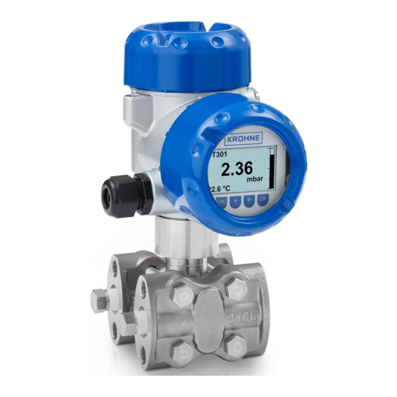
OPTIBAR DP 7060
OPTIBAR DP 7060
OPTIBAR DP 7060
OPTIBAR DP 7060
Differential pressure transmitter
Category
ATEX II 1/2G, 2G Ex db ia IIC T6...T1 Ga/Gb, Gb
IECEx Ex db ia IIC T6...T1 Ga/Gb, Gb
Housing
Aluminium: Single chamber, double chamber
Stainless steel (precision casting): Single chamber, double chamber
© KROHNE 05/2017 - 4005720001 - AD OPTIBAR 7060 Ex db ia R01en
Supplementary Instructions
Supplementary Instructions
Supplementary Instructions
Supplementary Instructions
Advertisement
Table of Contents

Related Manuals for KROHNE OPTIBAR DP 7060


Summary of Contents for KROHNE OPTIBAR DP 7060
- Page 1 ATEX II 1/2G, 2G Ex db ia IIC T6...T1 Ga/Gb, Gb IECEx Ex db ia IIC T6...T1 Ga/Gb, Gb Housing Aluminium: Single chamber, double chamber Stainless steel (precision casting): Single chamber, double chamber © KROHNE 05/2017 - 4005720001 - AD OPTIBAR 7060 Ex db ia R01en...
-
Page 2: Table Of Contents
4.7 Installation / mounting ....................14 4.8 Protection type flameproof enclosure Ex "d" ..............14 4.9 Mounting of the OPTIBAR DP 7060 VGK7*A/W/V E/Z/6/7 with remote housing ... 16 4.10 Size and type of thread for the "Ex-d" cable entries ........... 16 4.11 Removal and replacement of the red thread/dust cover.......... -
Page 3: Safety Instructions
As an option, the display and adjustment module can also be mounted. The OPTIBAR DP 7060 VGK7*A/W/V E/Z/6/7 are suitable for use in hazardous atmospheres of all combustible materials of explosion group IIA, IIB and IIC for applications requiring category 1/2G or 2G equipment. -
Page 4: Approval According To The Iecex Scheme
SAFETY INSTRUCTIONS OPTIBAR DP 7060 1.3 Approval according to the IECEx scheme Conformity with IECEx standards was tested in accordance with the IECEx Certification Scheme for Explosive Atmospheres acc. to IEC 60079-0, IEC 60079-1, IEC 60079-11 and IEC 60079-26. The number of the IECEx certificate is: IECEx TUN 16.0035X... -
Page 5: Device Description
The marking of the entire device is on the housing, where the following identification plate can be found. Figure 2-1: Example for an ATEX nameplate for a OPTIBAR DP 7060 1 Approvals and Ex-designation 2 Ingress protection and material of wetted parts... -
Page 6: Iecex Marking
The marking of the entire device is on the housing, where the following identification plate can be found. Figure 2-2: Example for an IECEx nameplate for a OPTIBAR DP 7060 1 Approvals and Ex-designation 2 Ingress protection and material of wetted parts... -
Page 7: Device Category
DEVICE DESCRIPTION OPTIBAR DP 7060 2.4 Device category Category 1/2G equipment (EPL-Ga/Gb equipment Category 1/2G equipment (EPL-Ga/Gb equipment) Category 1/2G equipment (EPL-Ga/Gb equipment Category 1/2G equipment (EPL-Ga/Gb equipment The process connection element is installed in the separating wall, which separates areas in which equipment of category 2G or 1G are required. -
Page 8: Ambient Temperature / Temperature Classes
2.6 Ambient temperature / temperature classes OPTIBAR DP 7060 VGK7*A/W/V E/Z/6/7 with integrated electronics Z (4 OPTIBAR DP 7060 VGK7*A/W/V E/Z/6/7 with integrated electronics Z (4 … 20 mA), 20 mA), OPTIBAR DP 7060 VGK7*A/W/V E/Z/6/7 with integrated electronics Z (4... -
Page 9: Temperature Derating
DEVICE DESCRIPTION OPTIBAR DP 7060 2.6.1 Temperature derating Category 1/2G equipment Category 1/2G equipment Category 1/2G equipment Category 1/2G equipment Temperature class Process temperature range at the Ambient temperature range at measuring cell the housing and at the electronics T1...T4 -40...55°C / -40...131°F... -
Page 10: Electrical Data
(spring contacts in the electronic compartment) The metallic parts of OPTIBAR DP 7060 VGK7*A/W/V E/Z/6/7 are electrically connected with the ground terminals. The supply and signal circuit is reliably isolated from parts which can be grounded by a galvanic isolation. -
Page 11: With Electronics P (Profibus Pa), F (Foundation Fieldbus)
(spring contacts in the electronic compartment) The metallic parts of OPTIBAR DP 7060 VGK7*A/W/V E/Z/6/7 are electrically connected with the ground terminals. The supply and signal circuit is reliably isolated from parts which can be grounded by a galvanic isolation. -
Page 12: Installation
INSTALLATION OPTIBAR DP 7060 3.1 Installation Installation and setup must be carried out according to the applicable installation standards (e.g. EN 60079-14 or IEC 60079-14) by qualified personnel trained in explosion protection. The information given in the manuals and the supplementary instructions must be observed at all times. -
Page 13: Further Notes
EN 60079-14 or IEC 60079-14 Chapter 12.3. 4.4 Earth In order to avoid the danger of electrostatic charging of the metallic parts, the OPTIBAR DP 7060 VGK7*A/W/V E/Z/6/7, used as category 1/2G equipment, must be electrostatically connected to the local equipotential bonding, e.g. -
Page 14: Impact And Friction Sparks
OPTIBAR DP 7060 4.5 Impact and friction sparks When used as category 1/2G equipment, the OPTIBAR DP 7060 VGK7*A/W/V E/Z/6/7 in light alloy (aluminium/titanium) versions must be mounted in such a way that sparks from impact and friction between light alloy and steel (except stainless steel, if the presence of rust particles can be excluded) cannot occur. - Page 15 FURTHER NOTES OPTIBAR DP 7060 The connecting cables, cable entries and screw plugs or pipeline sealing mechanisms must be suitable for the lowest ambient temperature. Prior to start-up, ensure that the cover of the "Ex-d" electonic compartment is screwed in all the way until it stops.
-
Page 16: Mounting Of The Optibar Dp 7060 Vgk7*A/W/V E/Z/6/7 With Remote Housing
4.9 Mounting of the OPTIBAR DP 7060 VGK7*A/W/V E/Z/6/7 with remote housing With the version with remote housing of the pressure transmitter OPTIBAR DP 7060 VGK7*A/W/V E/Z/6/7 the equipotential bonding must be provided in the complete mounting area of the connection cable between electronics housing and transmitter housing. -
Page 17: Removal And Replacement Of The Red Thread/Dust Cover
FURTHER NOTES OPTIBAR DP 7060 4.11 Removal and replacement of the red thread/dust cover Depending on the version, the thread or dust covers that are screwed in upon delivery of the device must be removed prior to start-up. The openings must be closed prior to start-up using a method permitted for the protection type. -
Page 18: Notes
NOTES OPTIBAR DP 7060 www.krohne.com 05/2017 - 4005720001 - AD OPTIBAR 7060 Ex db ia R01en... - Page 19 NOTES OPTIBAR DP 7060 05/2017 - 4005720001 - AD OPTIBAR 7060 Ex db ia R01en www.krohne.com...
- Page 20 • Process Analysis • Services Head Office KROHNE Messtechnik GmbH Ludwig-Krohne-Str. 5 47058 Duisburg (Germany) Tel.: +49 203 301 0 Fax: +49 203 301 10389 info@krohne.com The current list of all KROHNE contacts and addresses can be found at: www.krohne.com...
Need help?
Do you have a question about the OPTIBAR DP 7060 and is the answer not in the manual?
Questions and answers