Advertisement
Quick Links
An ISO 9001:2008 Certified Company
Specifications
Line
Armature
Voltage
Voltage Range
Model
(VAC)
(VDC)
115
0 - 90
RGA440-3
230
0 - 180
115
0 - 90
RGA440-10
230
0 - 180
AC Line Voltage
......................................................115/230 VAC ± 10%, 50/60 Hz, single phase
Form Factor
...................................................................................................1.37 at base speed
Field Voltage with 115 VAC line voltage
..............................................................50 or 100 VDC
with 230 VAC line voltage
............................................................100 or 200 VDC
Maximum Field Current
...................................................................................................1 Amp
Accelera�on Time Range
..................................................................................0.5 - 15 seconds
Decelera�on Time Range
..................................................................................0.5 - 15 seconds
Analog Input Voltage Range (Signal must be isolated)
.........................................0 to ± 10 VDC
Input Impedance (S0 to S2)
........................................................................................32K ohms
Load Regula�on with Armature Feedback
..........................................................1% base speed
Load Regula�on
with Tachogenerator Feedback
.............................................0.1% base speed
Speed Range with Armature Feedback
................................................................................50:1
Speed Range
with Tachogenerator Feedback
......................................................................60:1
Vibra�on (0 - 50 Hz)
............................................................................................0.5G maximum
(>50 Hz)
...............................................................................................0.1G maximum
Ambient Temperature Range
...................................................................................10°C - 55°C
Weight
..............................................................................................................................7.8 lbs
Safety Cer�fica�ons..................................................
UL/cUL Listed Equipment, file # E132235
Safety
Cer�fica�ons..................................................
CSA Cer�fied Component, file # LR41380
Short Circuit Current Ra�ng
Types of Branch
Drive Model
Maximum
Maximum
Circuit Protec�on
Current, A
Voltage, V
Non-�me
RGA440-10
10,000
240 V
Delay
K5 Fuse
Installation
Moun�ng
NEMA 4X cased drives come with three 0.88 inch (22 mm) conduit holes at the bo�om of the case. The
drives may be ver�cally wall mounted using the four 0.19 inch (5 mm) slo�ed holes on the a�ached
heat sink. For loads less than 5 amps, the drives may be bench mounted horizontally or operated
without moun�ng.
1. Install the moun�ng screws.
2. For access to the terminal strip, turn the slo�ed screw on the front cover counterclockwise un�l it is
2.
it is free from the case. The right side of the cover is hinged to the case. Pull the slo�ed screw to
2.
open the case.
3. Carefully remove the conduit knockouts by tapping them into the case and twis�ng them off with
3.
pliers.
4. Install conduit hardware through the 0.88 inch (22 mm) knockout holes. Connect external wiring to
4.
the terminal block.
5. Grasp the slo�ed screw and �lt the front cover back into place. Avoid pinching any wires between
5.
the front cover and the case.
6. Turn the slo�ed screw clockwise un�l �ght to secure the front cover.
7. Set the POWER switch to the OFF posi�on before applying AC line voltage.
Wiring
Use 18 - 24 AWG wire for logic wiring.
Use 14 - 16 AWG wire for AC line (L1, L2 115V, L2 230V) and motor (A1, A2, F1, F2) wiring.
Shielding Guidelines
As a general rule, it is recommended to shield all conductors. If it is not prac�cal to shield power
conductors, it is recommended to shield all logic-level leads. If shielding of logic-level leads is not
prac�cal, the user should twist all logic leads with themselves to minimize induced noise. Refer to
the user's manual for details on earth grounding shielded wires and filtering.
Fusing
The drives provide on board fusing for the AC line (L1, L2 (230)). Fuses are fast ac�ng fuses. RGA440-3
models contain fuses rated for 8A at 250 VAC. RGA440-10 models contain fuses rated for 20A at
250 VAC.
RGA440
4Q SCR NEMA 4X Adjustable Speed Drive
for PMDC or Field Wound Brush Motors
READ ALL SAFETY WARNINGS BEFORE INSTALLING THIS EQUIPMENT
Continuous
Armature
• DO NOT INSTALL, REMOVE, OR REWIRE THIS EQUIPMENT WITH POWER APPLIED. Have a
Armature
Horsepower
•
qualified electrical technician install, adjust and service this equipment. Follow the Na�onal
Current (Amps)
Range
•
Electrical Code and all other applicable electrical and safety codes, including the provisions of the
1/20 - 1/8
•
Occupa�onal Safety and Health Act (OSHA), when installing equipment.
3.0
1/10 - 1/4
• Circuit poten�als are at 115 or 230 VAC above earth ground. Avoid direct contact with the printed
•
circuit board or with circuit elements to prevent the risk of serious injury or fatality. Use a non-
1/4 - 1
10.0
•
metallic screwdriver for adjus�ng the calibra�on trim pots. Use approved personal protec�on
1/2 - 2
•
equipment and insulated tools if working on this drive with power applied.
• Reduce the chance of an electrical fire, shock, or explosion by using proper grounding, over-current
•
protec�on, thermal protec�on, and enclosure. Follow sound maintenance procedures.
• ACE strongly recommends the installa�on of a master power switch in the line voltage input. The
•
switch contacts should be rated for 250 VAC and 200% of motor nameplate current.
• Removing AC line power is the only acceptable method for emergency stopping. Do not use
•
regenera�ve braking, decelera�ng to minimum speed, or coas�ng to a stop for emergency stopping.
•
They may not stop a drive that is malfunc�oning. Removing AC line power is the only acceptable
•
method for emergency stopping.
• Line star�ng and stopping (applying and removing AC line voltage) is recommended for infrequent
•
star�ng and stopping of a drive only. Regenera�ve braking, decelera�ng to minimum speed, or
•
coas�ng to a stop is recommended for frequent starts and stops. Frequent star�ng and stopping can
•
produce high torque. This may cause damage to motors.
• Do not disconnect any of the motor leads from the drive unless power is removed or the drive is
•
disabled. Opening any one lead while the drive is running may destroy the drive.
• The field output is for shunt wound motors only. Do not make any connec�ons to F1 and F2 when
•
using a permanent magnet motor.
• Change voltage switch se�ngs only when the drive is disconnected from AC line voltage. Make sure
•
both switches are set to their correct posi�on. If the switches are improperly set to a lower voltage
•
posi�on, the motor will not run at full voltage and may cause damage to the transformer. If the
•
switches are improperly set to a higher voltage, the motor will overspeed, which may cause motor
•
damage, or result in bodily injury or loss of life.
Maximum
Ra�ng of
• Under no circumstances should power and logic level wires be bundled together.
Overcurrent
• This product does not have internal solid state motor overload protec�on. It does not contain speed-
Protec�on
Inverse
•
sensi�ve overload protec�on, thermal memory reten�on, or provisions to receive and act upon
Time
•
signals from remote devices for over temperature protec�on. If motor protec�on is needed in the
30 A
Circuit
•
end-use product, it needs to be provided by addi�onal equipment in accordance with NEC standards.
Breaker
Line Input
Connect the AC line power leads to terminals 1 and 2 if using 115 VAC line power or to terminals
1 and 3 if using 230 VAC line power.
Motor
Connect the DC armature leads to terminals A1 and A2. If the motor does not spin in the desired
direc�on, power down the drive and reverse these connec�ons.
Field
At 115 VAC, connect the field leads to terminals F1 and L1 for a 50 VDC field or to F1 and F2 for a 100
VDC field. At 230 VAC, connect the field leads to terminals F1 and L1 for a 100 VDC field or to F1 and
F2 for a 200 VDC field. Do not make any connec�ons to F1 and F2 if using a permanent magnet motor.
1
2
3
S
F
1
F
2
F
A
S
I T
N
G
F
U
S
N
L
Y
S
L
1
L
2
2
3
0
V
L1
L2
230V
115
VAC
230 VAC
AC LINE
VOLTAGE
Safety Warnings
POWER
INHIBIT SWITCH
S
O
5
0
2
(OPTIONAL)
TACHOGENERATOR
(OPTIONAL)
C
5
0
2
I
C
5
0
1
W
5
0
2
C
I
5
0
2
W
5
0
1
C
5
0
3
ENABLE
T
B
5
0
1
SWITCH
L
2
G
N
D
F
1
F
2
A
2
A
1
1
1
5
V
T
B
5
0
2
(OPTIONAL)
C
5
0
5
GND F1
F2
A2
A1
L2
115V
NOTE: DO NOT
make any connections
MOTOR
to F1 and F2 is using
a permanet magnet
motor.
FIELD
14300 De La Tour Drive
South Beloit, IL 61080
Phone: (844) AMCNTRL
Fax: (800) 394-6334
www.americancontrolelectronics.com
Dimensions
10.22
[260]
9.80
[249]
0.22
[6]
WARNING: DISCONNECT FROM SUPPLY BEFORE OPENING THIS COVER.
SEPARATE MOTOR OVERCURRENT AND OVERLOAD PROTECTION IN ACCORDANCE WITH
5.51
1.50
2.31
[140]
[38]
[59]
4.78
[121]
ALL DIMENSIONS IN INCHES [MILLIMETERS]
Connections
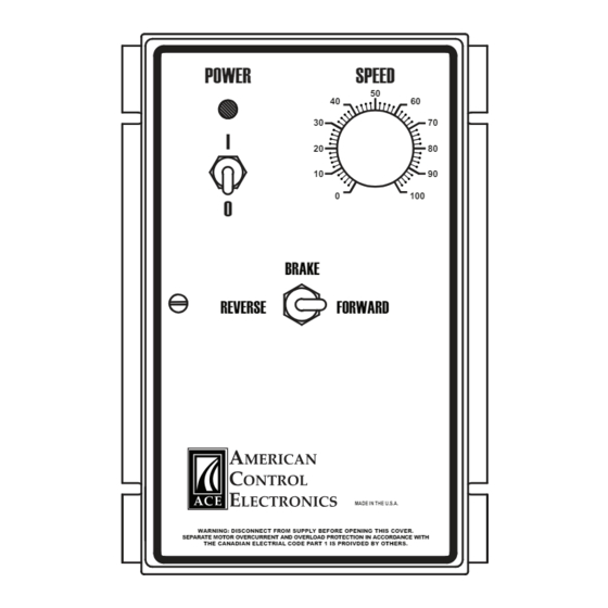
Speed Adjust Poten�ometer (Pre-wired)
RGA440 series drives are pre-installed with a 10K ohm, 1/4 W poten�ometer for speed control.
Forward-Brake-Reverse Switch (Pre-wired)
RGA440 series drives are pre-installed with a Forward-Brake-Reverse Switch. When set to forward
the switch connects the poten�ometer with S1, allowing unidirec�onal control in the forward
direc�on. When set to reverse, the switch connects the poten�omter with S3, allowing unidirec�onal
control in reverse. When set to Brake, the switch closes the RB1 and RB2 connec�ons, regenera�vely
braking the motor at a rate set by either the FWD ACC or REV ACC trim pots.
Inhibit
Short the INHIBIT terminals to regenera�vely brake the motor to zero speed. The INHIBIT terminals
bypass the FWD ACC and REV ACC trim pots. Open the INHIBIT terminals to accelerate the motor to
set speed. ACE offers two accessory plug harnesses for connec�ng to the inhibit terminals; part
number 201-0024 [18 in (46 cm) leads] and part number 201-0079 [36 in (91 cm) leads]. Do not use
the inhibit for emergency stopping.
NOTE: DO NOT
make any connections
to T1 and T2 unless
Enable (Inhibit-Run)
using a tachogenerator.
Short pins 1 and 2 on terminal SO502 to coast the motor to zero speed. Short pins 2 and 3 on terminal
SO502 to accelerate the motor to set speed. If no Enable switch is desired, jumper pins 2 and 3 on
SO502 (factory default). ACE offers an accessory plug harness for connec�ng to the enable terminals;
part number 201-0197 [18 in (46 cm) leads]. Do not use the enable for emergency stopping.
Tachogenerator
Using tachogenerator feedback improves speed regula�on from approximately 1% of motor base
speed to 0.1% of motor base speed. Use tachogenerators rated from 7 VDC per 1000 RPM to 50 VDC
per 1000 RPM. Connect the tachogenerator to terminals T1 (posi�ve) and T2 (nega�ve).
+15 and -15
RGA series drive can supply a regulated +15 and -15 VDC voltage (each sourcing 15 mA maximum) with
respect to RB1 or T1 to isolated, external devices.
Full manual available online
6.90 [175]
6.30 [160]
1.40 [36]
POWER
SPEED
50
40
60
30
70
I
20
80
10
90
0
100
0
BRAKE
7.00 [178]
REVERSE
FORWARD
MADE IN THE U.S.A.
THE CANADIAN ELECTRIAL CODE PART 1 IS PROIVDED BY OTHERS.
1.50 [38]
1.45 [37]
Ø0.88 [22]
0.12
[3]
LOGIC
Advertisement

Related Manuals for American Control Electronics RGA440


Summary of Contents for American Control Electronics RGA440
- Page 1 1000 RPM. Connect the tachogenerator to terminals T1 (posi�ve) and T2 (nega�ve). Fusing GND F1 The drives provide on board fusing for the AC line (L1, L2 (230)). Fuses are fast ac�ng fuses. RGA440-3 230V 115V +15 and -15 models contain fuses rated for 8A at 250 VAC.
- Page 2 Deadband is factory Copyright 2017 by American Control Electronics® - All rights reserved. No part of this document may calibrated to approximately the 3 o’clock posi�on for 60 Hz AC line opera�on. Recalibrate the be reproduced or retransmi�ed in any form without wri�en permission from American Control...
Need help?
Do you have a question about the RGA440 and is the answer not in the manual?
Questions and answers