Advertisement
Quick Links
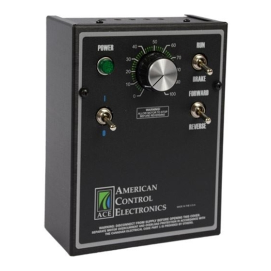
Speed or Torque Mode for PMDC Brushed Motors
Specifications
Line
Armature
Voltage
Voltage Range
Model
(VAC)
(VDC)
Current (Amps)
115
0 - 90
LGD430-1.5
230
0 - 180
115
0 - 90
LGD430-10
230
0 - 180
* Heat sink kit HSK- 0002 must be used when the continuous output current is over 5 amps.
AC Line Voltage
......................................................115/230 VAC ± 10%, 50/60 Hz, single phase
Form Factor
...................................................................................................1.37 at base speed
Acceleration Time Range
..................................................................................0.5 - 17 seconds
Deceleration Time Range
..................................................................coast to stop - 25 seconds
Analog Input Range (Signal must be isolated; S1 to S2)
............................................0 - 2.5 VDC
Input Impedance (S1 to S2)
.....................................................................................>100K ohms
Load Regulation
....................................................................................1% base speed or better
Speed Range
........................................................................................................................60:1
Vibration (0 - 50 Hz)
...........................................................................................0.5G maximum
(>50 Hz)
..............................................................................................0.1G maximum
Ambient Temperature Range
...................................................................................10°C - 40°C
Weight
..............................................................................................................................3.0 lbs
Safety Certifications..................................................
UL/cUL Listed Equipment, file # E132235
Safety
Certifications......................................................................
Safety
Certifications..................................................
CSA Certified Component, file # LR41380
Installation
Mounting
NEMA 1 cased drives come with two 0.88 inch (22 mm) conduit holes at the bottom of the case. The
drives may be vertically wall mounted or horizontally bench mounted using the three keyholes on the
back of the case.
1. For access to the keyholes and the terminal strip, remove the two screws from the front of the case
1.
by turning them counterclockwise. Grasp the front cover and pull it straight out.
2. Install the monting screws in the three keyholes.
3. Set the POWER switch to the OFF position before applying the AC line voltage.
4. Install conduit hardware through the conduit holes at the bottom of the case. Connect external
3.
wiring to the terminal block.
5. Reinstall the front cover. Avoid pinching any wires between the front cover and the case.
6. Reinstall the two screws on the front cover. Turn the screws clockwise to tighten.
Heat Sinking
The LGD430-10 requires an additional heat sink when the continuous armature current is above 5
amps. Use ACE heat sink kit part number HSK-0002. Use a thermally conductive heat sink compound
(such as Dow Corning 340® Heat Sink Compound) between the back of the case and the heat sink
surface for optimal heat transfer.
Wiring
Use 14 - 16 AWG wire for AC line and motor wiring.
Shielding Guidelines
As a general rule, ACE recommends shielding of all conductors. If it is not practical to shield power
conductors, ACE recommends shielding all logic-level leads. If shielding of logic-level leads is not
practical, the user should twist all logic leads with themselves to minimize induced noise. It may be
necessary to earth ground the shielded cable. If noise is produced by devices other than the drive,
ground the shield at the drive end. If noise is generated by the drive, ground the shield at the end
away from the drive. Do not ground both ends of the shield.
Fusing
LGD430 series drives provide fusing for the AC line (1, 3). Fuses are fast acting fuses. LGD430-1.5
models contain fuses rated for 3A at 250 VAC. LGD430-10 models contain fuses rated for 15A at
250 VAC.
LGD430
1Q SCR NEMA 1 Adjustable Speed Drive
with Reversing and Dynamic Braking and with
READ ALL SAFETY WARNINGS BEFORE INSTALLING THIS EQUIPMENT
Continuous
• DO NOT INSTALL, REMOVE, OR REWIRE THIS EQUIPMENT WITH POWER APPLIED. Have a
Armature
Horsepower
•
qualified electrical technician install, adjust and service this equipment. Follow the National
Range
•
Electrical Code and all other applicable electrical and safety codes, including the provisions of the
1/20 - 1/8
1.5
•
Occupational Safety and Health Act (OSHA), when installing equipment.
1/10 - 1/4
• Circuit potentials are at 115 or 230 VAC above earth ground. Avoid direct contact with the printed
1/8 - 1
•
circuit board or with circuit elements to prevent the risk of serious injury or fatality. Use a non-
10.0*
1/4 - 2
•
metallic screwdriver for adjusting the calibration trim pots. Use approved personal protection
•
equipment and insulated tools if working on this drive with power applied.
• Reduce the chance of an electrical fire, shock, or explosion by using proper grounding techniques,
•
over-current protection, thermal protection, and enclosure. Follow sound maintenance procedures.
• Removing AC line power is the only acceptable method for emergency stopping. Do not use
•
dynamic braking, decelerating to minimum speed, or coasting to a stop for emergency stopping.
•
They may not stop a drive that is malfunctioning. Removing AC line power is the only acceptable
•
method for emergency stopping.
• Line starting and stopping (applying and removing AC line voltage) is recommended for infrequent
•
starting and stopping of a drive only. Dynamic braking, decelerating to minimum speed, or coasting
•
to a stop is recommended for frequent starts and stops. Frequent starting and stopping can produce
•
high torque. This may cause damage to motors.
• Do not disconnect any of the motor leads from the drive unless power is removed or the drive is
•
disabled. Opening any one lead while the drive is running may destroy the drive.
• Change voltage switch settings only when the drive is disconnected from AC line voltage. Make sure
•
both switches are set to their correct position. If the switches are improperly set to a lower voltage
UL/cUL Overload Protection
•
position, the motor will not run at full voltage and may cause damage to the transformer. If the
•
switches are improperly set to a higher voltage, the motor will overspeed, which may cause motor
•
damage, or result in bodily injury or loss of life.
• Do not change the FORWARD/REVERSE switch while the motor is running. The motor must come
•
to a complete stop before reversing. Changing motor direction before allowing the motor to
•
completely stop will damage the drive and/or motor.
Line Input
Connect the AC line power leads to terminals 1 and 2 if using 115 VAC line power or to terminals 1 and 3
Connect the AC line power leads to terminals L1 and L2, or to a double-throw, single-pole master power
if using 230 VAC line power.
switch (recommended). The switch should be rated at a minimum of 250 VAC and 200% of motor current.
Motor
Connect the DC armature leads to terminals 4 and 5. If the motor does not spin in the desired direction,
Connect the DC armature leads to terminals A1 and A2. If the motor spins in the reverse of desired rotation,
power down the drive and reverse these connections.
Speed Potentiometer (Pre-wired)
LGD430 series drives are pre-installed with a 10K ohm, 1/4 W potentiometer for speed control.
to S2, and the supply to S3. If the potentiometer works inveresly of desired functionality, (i.e. to increase
Run/Stop Switch (Pre-wired)
motor speed, you must turn the potentiometer counterclockwise), power off the drive and swap the S1 and
LGD430 series drives are pre-installed with a Run/Stop switch. When set to Stop, this switch will inhibit
the drive, disconnect the motor armature, and connect a dynamic braking resistor across the motor. The
dynamic braking resistor allows the motor to stop quicker than if allowed to naturally coast to a stop.
Short the inhibit terminals to coast the motor to minimum speed. Open the INHIBIT terminals to
Forward/Reverse Switch (Pre-wired)
accelerate the motor to set speed. Twist inhibit wires and seperate them from power-carrying wires or
LGD430 series drives are pre-installed with a Forward/Reverse switch. This switch swaps the motor
sources of electrical noise. Use shielded cable if the inhibit wires are longer than 18 inches (46 cm). If
armature wires to change motor rotation direction. To use the Forward/Reverse Switch, first set the
shielded cable is used, ground only one end of the shield to earth ground. Do not ground both ends of
Run/Stop switch to Stop. When the motor has come to a complete stop, toggle the direction switch
and then set the Run/Stop switch to Run. Do not change the Forward/Reverse switch while the motor
is running.
ACE offers two accessory plug harnesses for connecting to the inhibit terminals; part number KTW-0001
Safety Warnings
POWER
Line Input
Motor
simply power down the drive and reverse these connections.
LOGIC
Speed Potentiometer
S1, the wiper
S3 connections.
Inhibit
the shield.
[18 in (46 cm) leads] and part number KTW-0002 [36 in (91 cm) leads].
14300 De La Tour Drive
South Beloit, IL 61080
Phone: (815) 624-6915
Fax: (815) 624-6965
www.americancontrolelectronics.com
Full manuals available online or use QR code
Dimensions
6.00 [125 ]
POWE R
I
WARNING !
ALLOW MOTO R TO STO P
BEFORE REVERSING
8.00 [203 ]
0
MADE IN THE U.S.A .
WARNING: DISCONNECT FROM SUPP LY BEFORE OPENING THIS C OV ER.
SEPA RA TE MOTOR O VERC URRENT AND O VERL OA D PR OTECTION IN A CCOR DA NCE WITH
THE CANADIAN ELECTRICAL CODE P ART 1 IS PRO VIDED BY OTHERS.
Ø0.88
[22] (2)
3.46 [88]
1.72
2.50
[44]
[64]
ALL DIMENSIONS IN INCHES [MILLIMETERS]
Connections
1
2
11 5
VA C
2 30
VA C
EARTH G R OU N D
( GREEN SCREW )
Ø0.19
C L
[5] (4)
1.7 9
RUN
[45 ]
2.50
2.50
[64]
[64]
BRAKE
FORWAR D
REVERSE
5.0 0
[127]
2.7 5
[70 ]
1.25 [32]
3
4
5
6
7
+
M O T OR
ARMA T U R E
-
Advertisement

Related Manuals for American Control Electronics LGD430


Summary of Contents for American Control Electronics LGD430
- Page 1 The LGD430-10 requires an additional heat sink when the continuous armature current is above 5 11 5 LGD430 series drives are pre-installed with a Run/Stop switch. When set to Stop, this switch will inhibit S3 connections. amps. Use ACE heat sink kit part number HSK-0002. Use a thermally conductive heat sink compound VA C the drive, disconnect the motor armature, and connect a dynamic braking resistor across the motor.
- Page 2 Current Limit Power LED Copyright 2012 by American Control Electronics ® - All rights reserved. No part of this document may be reproduced or retransmitted in any form without written permission from American Control Electronics ® . The information and technical data in this document are subject to change without notice. American Control Electronics ®...
Need help?
Do you have a question about the LGD430 and is the answer not in the manual?
Questions and answers