Advertisement
Quick Links
Specifications
Line
Armature
Voltage
Voltage Range
Model
(VAC)
(VDC)
Current (Amps)
115
0-12 or 0-24
DCH401-5
230
* Peak current rating for 10 seconds. Continuous current rating is 5 amps.
AC Line Voltage
......................................................115/230 VAC ± 10%, 50/60 Hz, single phase
Form Factor
...................................................................................................1.05 at base speed
Acceleration Time Range
..................................................................................0.5 - 16 seconds
Deceleration Time Range
..................................................................................0.5 - 16 seconds
Analog Input Voltage Range
.............................................................................0 - 5, 0 - 10 VDC
Input Impedance (S1 to S2)
.....................................................................................>100K ohms
Load Regulation
..................................................................................................1% base speed
Speed Range
........................................................................................................................80:1
Vibration (0 - 50 Hz)
............................................................................................0.5G maximum
(>50 Hz)
...............................................................................................0.1G maximum
Ambient Temperature Range
...................................................................................10°C - 40°C
Weight
............................................................................................................................1.34 lbs
Safety Certifications
..................................................UL/cUL Listed Equipment, file # E132235
Installation
Mounting
• Drive components are sensitive to electrostatic discharge. Avoid direct contact with the circuit
•
board. Hold the drive by the chassis or heat sink only.
• Protect the drive from dirt, moisture, and accidental contact.
• Provide sufficient room for access to the terminals and calibration trim pots.
• Mount the drive away from heat sources. Operate the drive within the specified ambient operating
•
temperature range.
• Prevent loose connections by avoiding excessive vibration of the drive.
• Mount the drive with its board in either a horizontal or vertical plane. Six 0.19" (5 mm) wide slots
•
in the chassis accept #8 pan head screws. Fasten either the large base or the narrow flange of the
•
chassis to the subplate.
• The chassis should be earth grounded.
Wiring
Use 18 - 24 AWG wire for logic wiring. Use 14 - 16 AWG wire for AC line and motor wiring.
Shielding Guidelines
As a general rule, ACE recommends shielding of all conductors. If it is not practical to shield power
conductors, ACE recommends shielding all logic-level leads. If shielding of logic-level leads is not
practical, the user should twist all logic leads with themselves to minimize induced noise. It may be
necessary to earth ground the shielded cable. If noise is produced by devices other than the drive,
ground the shield at the drive end. If noise is generated by the drive, ground the shield at the end
away from the drive. Do not ground both ends of the shield.
Fusing
DCH401-5 drives provide an on board fuse for the AC line (L1). Fuse is a fast acting fuse rated for 2A at
250 VAC.
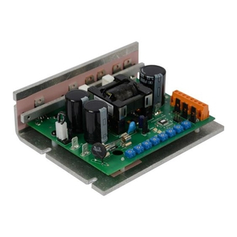
DCH401
4Q PWM microprocessor based Chassis
Adjustable Speed Drive
for Low Voltage PMDC Brush Motors
READ ALL SAFETY WARNINGS BEFORE INSTALLING THIS EQUIPMENT
Peak
Armature
• DO NOT INSTALL, REMOVE, OR REWIRE THIS EQUIPMENT WITH POWER APPLIED. Have a
Armature
Horsepower
•
qualified electrical technician install, adjust and service this equipment. Follow the National
Range
•
Electrical Code and all other applicable electrical and safety codes, including the provisions of the
1/50 - 1/20
7.5*
•
Occupational Safety and Health Act (OSHA), when installing equipment.
1/25 - 1/8
• Circuit potentials are at 115 or 230 VAC above earth ground. Avoid direct contact with the printed
•
circuit board or with circuit elements to prevent the risk of serious injury or fatality. Use a non-
•
metallic screwdriver for adjusting the calibration trim pots. Use approved personal protection
•
equipment and insulated tools if working on this drive with power applied.
• Reduce the chance of an electrical fire, shock, or explosion by using proper grounding techniques,
•
over-current protection, thermal protection, and enclosure. Follow sound maintenance procedures.
• ACE strongly recommends the installation of a master power switch in the line voltage input. The
•
switch contacts should be rated for 250 VAC and 200% of motor nameplate current.
• Removing AC line power is the only acceptable method for emergency stopping. Do not use
•
regenerative braking, decelerating to minimum speed, or coasting to a stop for emergency stopping.
•
They may not stop a drive that is malfunctioning. Removing AC line power is the only acceptable
•
method for emergency stopping.
• Line starting and stopping (applying and removing AC line voltage) is recommended for infrequent
•
starting and stopping of a drive only. Dynamic braking, decelerating to minimum speed, or coasting
•
to a stop is recommended for frequent starts and stops. Frequent starting and stopping can produce
•
high torque. This may cause damage to motors.
• Do not disconnect any of the motor leads from the drive unless power is removed or the drive is
•
disabled. Opening any one lead while the drive is running may destroy the drive.
• Change voltage switch settings only when the drive is disconnected from AC line voltage. Make sure
•
both switches are set to their correct position. If the switches are improperly set to a lower voltage
•
position, the motor will not run at full voltage and may cause damage to the transformer. If the
•
switches are improperly set to a higher voltage, the motor will overspeed, which may cause motor
•
damage, or result in bodily injury or loss of life.
• Under no circumstances should power and logic level wires be bundled together.
• Be sure potentiometer tabs do no make contact with the potentiometer's body. Grounding the
•
input will cause damage to the drive.
Input Power
Connect the AC line power leads to terminals L1 and L2. ACE recommends the use of a double-pole,
single-throw master power switch. The switch should be rated at a minimum of 250 VAC and 200%
of motor current.
Motor
Connect the DC armature leads to terminals A1 and A2. If the motor does not spin in the desired
direction, power down the drive and reverse these connections.
ST OP
SWITCH
AC LINE
VOLT AG E
115/230 VA C
-5
Safety Warnings
Connections
POWER
12 or 24 VDC
A1
A2
+ BUS
J501
230 VAC
115 VAC
L2
- BUS
L1
J503
1
POWER
J502
2
3
CURR LIMIT
J504
24V
12V
1
2
FWD
REV
FWD
REV
3
MIN
FWD
REV
MAX
MAX
CURR
CURR
IR
J505
SPEED
SPEED
LIMIT
LIMIT
COMP
SPEED
1
ACCEL
ACCEL
2
3
14300 De La Tour Drive
Phone: (815) 624-6915
www.americancontrolelectronics.com
Dimensions
J501
230 VAC
115 VAC
4.818 [122.38]
L2
L1
24V 12V
FWD
REV
FWD
REV
MAX
MAX
ACCEL
ACCEL
SPEED
SPEED
0.750 [19.05]
5.630 [143.00]
6.130 [155.70]
5.630 [143.00]
2.00 [50.80]
ALL DIMENSIONS IN INCHES [MILLIMETERS]
LOGIC
Speed Potentiometer
Use a 10K ohm, 1/4 W potentiometer for speed control. Connect the counter-clockwise end of the
potentiometer to S1, the wiper to S2, and the clockwise end to S3. If the potentiometer works inversely
inveresly of desired functionality, (i.e. to increase motor speed, you must turn the potentiometer
counterclockwise), power off the drive and swap the S1 and S3 connections.
Forward & Reverse Inhibit
Connect a forward inhibit switch to terminals 6 and 8 and a reverse inhibit switch to terminals 7 and 8.
Activating an INHIBIT connection regeneratively brakes the motor to a stop. The inhibits bypass the
FWD ACCEL and REV ACCEL trim pots. The forward inhibit switch has no effect if the motor is running in
reverse, and vice versa. If the use of only one inhibit switch is desired, jumper terminals 6 and 7 and
then connect the switch to terminal 8 and either terminals 6 or 7. If no inhibit switches are desired,
leave terminals 6, 7, and 8 open and set jumper J505 for "NORMAL". See the STARTUP section for
directions on how to set the INHIBITS for either normally open or normally closed operation using
jumper J505. Do not use the Inhibit functions for emergency stopping.
Direction
Connect a direction switch to the COM and DIR terminals. Close the switch to change direction.
1 (S3)
2 (S2)
3 (S1, COM)
4 (DIR)
5 (COM)
6 (FW I )
7 (R V I )
8 (COM)
South Beloit, IL 61080
•
Fax: (815) 624-6965
•
A1
A2
1.618 [41.10]
+ BUS
2.45 [62.23]
- BUS
J503
1
POWER
2
J502
3
J504
CURR LIMIT
1
2
3
FWD
REV
J505
CURR
CURR
IR
MIN
1
LIMIT
LIMIT
SPEED
COMP
2
3
0.250 [6.35]
1.48 [37.59]
Advertisement

Related Manuals for American Control Electronics DCH401-5


Summary of Contents for American Control Electronics DCH401-5
- Page 1 Do not ground both ends of the shield. 230 VAC 115 VAC Fusing DCH401-5 drives provide an on board fuse for the AC line (L1). Fuse is a fast acting fuse rated for 2A at 1 (S3) 250 VAC. 2 (S2)
- Page 2 CCW for a shorter deceleration time. Copyright 2011 by American Control Electronics ® - All rights reserved. No part of this document may be reproduced or retransmitted in any form without written permission from American Control Electronics ® .
Need help?
Do you have a question about the DCH401-5 and is the answer not in the manual?
Questions and answers