
Related Manuals for American Control Electronics Minarik DRIVES RG500 Series


Summary of Contents for American Control Electronics Minarik DRIVES RG500 Series
- Page 1 A n A mer ican C ont ro l Elec tron ics Bran d RG50 0 S ER IES USER MANUAL RG 5 00 UA RG 5 00 UA- P C M RG 5 00 A RG 5 10 UA RG 5 10 UA- P C M RG 5 10 A w w w .
- Page 2 American Control Electronics®. The information and technical data in this document are subject to change without notice. American Control Electronics® makes no warranty of any kind with respect to this material, including, but not limited to, the implied warranties of its merchantability and fitness for a given purpose.
- Page 3 RG500 Series Safety First! S A F E T Y W A R N I N G S Text in gray boxes denote important safety tips or warnings. Please read these instructions carefully before performing any of the procedures contained in this manual. WARNING! •...
-
Page 4: Table Of Contents
RG500 Series Table of Contents Section 1. Regenerative Drives ..........1 Section 2. Specifications ............. 2 Section 3. Dimensions ............4 Section 4. Installation ............8 Heat Sinking ................. 8 Chassis .................. 8 NEMA 4X ................8 Mounting ..................9 Chassis ................. - Page 5 RG500 Series Section 5. Operation ............27 Before Applying Power ..............27 Select Switches ................28 Input Voltage Select (SW501, SW502) ........28 Armature Voltage Select (SW503) .........28 Feedback Select (SW504) .............28 Signal Select (SW501) (-PCM models) ........29 Input Voltage Select (SW502) (-PCM models) ......29 Startup (Chassis models) ..............30 Startup (NEMA 4X models) ............31 Starting and Stopping Methods ............32...
- Page 6 RG500 Series Section 7.Application Notes ..........48 Direction Switch ................48 Multiple Fixed Speeds ..............49 Adjustable Speeds Using Potentiometers In Series ......50 Independent Adjustable Speeds ............51 Independent Adjustable Forward and Reverse Speeds ....52 RUN/JOG Switch - Inhibit Connection ..........53 RUN/JOG Switch - Potentiometer Connection ........54 Leader-Follower Application ............55 Single Speed Potentiometer Control Of Multiple Drives ....56 Section 8.
- Page 7 RG500 Series List of Tables Table 1 Recommended Line Fuse Sizes ..........15 Table 2 Short Circuit Current Ratings ..........15 Table 3 Field Output Connections ..........17 List of Figures Figure 1 Four Quadrant Operation ..........1 Figure 2 RG500UA and RG510UA Dimensions ........4 Figure 3 RG500UA-PCM and RG510UA-PCM Dimensions ....
- Page 8 RG500 Series List of Figures Figure 1 Four Quadrant Operation ..........1 Figure 2 RG500UA and RG510UA Dimensions ........4 Figure 3 RG500UA-PCM and RG510UA-PCM Dimensions ....5 Figure 4 RG500A and RG510A Dimensions ........6 Figure 5 223-0235 Dimensions ............7 Figure 6 Speed Adjust Potentiometer ..........10 Figure 7...
- Page 9 RG500 Series Figure 29 RUN/JOG Switch - Inhibit Connection .......53 Figure 30 RUN/JOG Switch - Speed Adjust Potentiometer Connection . 54 Figure 31 Leader-Follower Application ..........55 Figure 32 Single Speed Potentiometer Control of Multiple Drives ..56...
-
Page 10: Section 1. Regenerative Drives
RG500 Series Section 1. Regenerative Drives Most non-regenerative, variable speed, DC drives control current flow to a motor in one direction. The direction of current flow is the same direction as the motor rotation. Non-regenerative drives Quadrant II Quadrant I operate in Quadrant I, Quadrant III Quadrant IV... -
Page 11: Section 2. Specifications
RG500 Series Section 2. Specifications Maximum HP Range HP Range Armature with 90 VDC with 180 VDC Model Current (ADC) Motor Motor Enclosure RG510UA 1/20 - 1/4 1/10 - 1/2 Chassis RG510UA-PCM Chassis RG510A NEMA 4X RG500UA* 10.0 1/8 - 1 1/4 - 2 Chassis RG500UA-PCM*... - Page 12 RG500 Series Input Impedance Non -PCM models (RB1 to S2) 32K ohms -PCM models (Voltage Signal) >25K ohms -PCM models (1-5 mA Signal) 1K ohms -PCM models (4-20 mA Signal) 235 ohms -PCM models (10-50 mA Signal) 100 ohms Form Factor 1.37 at base speed Load Regulation with Armature Feedback...
-
Page 13: Section 3. Dimensions
RG500 Series Section 3. Dimensions 0.19 [5] R502 R503 ARMATURE FEEDBACK 180 ARM TACH SW503 SW504 T504 T503 8.90 [228] T502 C501 T501 8.40 [213] R501 SO502 T505 SW502 C502 IC501 FU501 FU502 FAST ACTING FUSES ONLY IC502 SW501 C503 TB501 TB502 C505... -
Page 14: Figure 3 Rg500Ua-Pcm And Rg510Ua-Pcm Dimensions
RG500 Series 0.19 [5] 8.90 [226] 8.40 [213] T505 SW502 C502 IC501 FU501 FU502 FAST ACTING FUSES ONLY IC502 SW501 C503 TB501 TB502 C505 GND F1 230V 115V 3.50 [89] 4.78 [121] 3.07 [78] 1.85 [47] 0.92 [23] ALL DIMENSIONS IN INCHES [MILLIMETERS] Figure 3. -
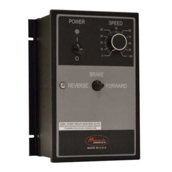
Page 15: Figure 4 Rg500A And Rg510A Dimensions
RG500 Series 6.90 [175] 6.30 [160] POWER SPEED 1.40 [36] BRAKE 10.22 [260] REVERSE FORWARD 9.80 [249] 7.00 [178] 0.22 1.45 [37] 5.51 [140] 4.78 [121] 2.31 [59] 0.12 1.50 [38] 1.50 [38] ALL DIMENSIONS IN INCHES [MILLIMETERS] Figure 4. RG500A and RG510A Dimensions... -
Page 16: Figure 5 223-0235 Dimensions
RG500 Series 6.90 [175] 6.60 [168] 0.3 [8] 1.375 [35] 8.375 [213] 9.78 [249] ALL DIMENSIONS IN INCHES [MILLIMETERS] Figure 5. 223-0235 Dimensions... -
Page 17: Section 4. Installation
RG500 Series Section 4. Installation Do not install, rewire, or remove this control with input power applied. Failure to heed this warning may result in fire, explosion, or serious injury. Make sure you read and understand the Safety WARNING! Precautions on page i before attempting to install this product. -
Page 18: Mounting
RG500 Series Mounting Chassis • Drive components are sensitive to electrostatic discharge. Avoid direct contact with the circuit board. Hold the drive by the heat sink only. • Protect the drive from dirt, moisture, and accidental contact. • Provide sufficient room for access to the terminals and calibration trim pots. -
Page 19: Speed Adjust Potentiometer
RG500 Series Speed Adjust Potentiometer Be sure that the potentiometer tabs do not make contact with the potentiometer’s body. Grounding the input will cause damage to the drive. WARNING! If using a remote potentiometer with a chassis drive, mount the speed adjust potentiometer through a 0.38 in. -
Page 20: Nema 4X
RG500 Series Mounting (NEMA 4X Enclosures) NEMA 4X cased drives come with two 0.88 inch (22 mm) conduit knockout holes at the bottom of the case. The units may be vertically wall mounted using the four 0.19 inch (5 mm) slotted holes on the attached heat sink. -
Page 21: Wiring
RG500 Series Wiring Do not install, rewire, or remove this control with input power applied. Failure to heed this warning may result in fire, explosion, or serious injury. WARNING! Circuit potentials are at 115 or 230 VAC above ground. To prevent the risk of injury or fatality, avoid direct contact with the printed circuit board or with circuit elements. -
Page 22: Shielding Guidelines
RG500 Series Shielding Guidelines Under no circumstances should power and logic level leads be bundled together. Induced voltage can cause unpredictable behavior in any electronic device, including motor controls. WARNING! As a general rule, Minarik Drives recommends shielding of all conductors. If it is not practical to shield power conductors, it is recommended to shield all logic-level leads. -
Page 23: Line Fusing
RG500 Series Line Fusing Models RG500UA, RG500UA and RG500A are preinstalled with 20 amp fuses. Models RG510UA, RG510UA-PCM and RG510A are preinstalled with 8 amp fuses. Preinstalled line fuses are rated for maximum horsepower. If the horsepower rating of the motor being used is less than the maximum horsepower rating of the drive, the line fuse may have to be replaced with a lower rated one. -
Page 24: Table 1 Recommended Line Fuse Sizes
RG500 Series Table 1. Recommended Line Fuse Sizes 90 VDC 180 VDC Maximum DC AC Line Motor Motor Armature Current Fuse Size Horsepower Horsepower (amps) (amps) 1/20 1/10 1/15 1 1/2 Minarik Drives offers fuse kits. See Section 9: Accessories and Replacement Parts for fuse kit part numbers. -
Page 25: Connections
RG500 Series Connections Do not connect this equipment with power applied. Failure to heed this warning may result in fire, explosion, or serious injury. WARNING! Minarik Drives strongly recommends the installation of a master power switch in the voltage input line, as shown in Figures 11 and 12 on pages 24 and 25. -
Page 26: Field Output Connections
RG500 Series Field Output Connections The field output is for shunt wound motors only. Do not make any connections to F1 and F2 when using a permanent magnet motor. WARNING! See Table 3 for field output connections. Use 14 - 16 AWG wire to connect the field output to a field / shunt wound motor. -
Page 27: Speed Adjust Potentiometer
RG500 Series Speed Adjust Potentiometer Use a 10K ohm, 1/4 W potentiometer for speed control. The motor can operate in one direction (unidirectional) or two directions (bidirectional) depending on how the speed adjust potentiometer is connected to the drive. For unidirectional operation in the foward direction, connect the speed adjust potentiometer as shown in Figure 7(a). -
Page 28: Speed Adjust Potentiometer (-Pcm Models)
RG500 Series Speed Adjust Potentiometer (-PCM models) Use a 10K ohm, 1/4 W potentiometer for speed control. The motor can operate in one direction (unidirectional) or two directions (bidirectional) depending on how the speed adjust potentiometer is connected to the drive. -
Page 29: Analog Input Signal
RG500 Series Analog Input Signal Instead of using a speed adjust potentiometer, the drive may be wired to follow an analog input voltage signal that is isolated from earth ground (Figure 9). Connect the signal common (–) RB1. Connect the signal input (+) to S2. -
Page 30: Analog Input Signal (-Pcm Models)
RG500 Series Analog Input Signal (-PCM models) Instead of using a speed adjust potentiometer, the drive may be wired to follow an analog input voltage or current signal that is either isolated or non-isolated from earth ground. Connect the signal common (-) to terminal 7 (COM). -
Page 31: And -15
RG500 Series +15 and -15 Do not short the +15 and -15 terminals for any reason. Shorting these terminals will damage the drive. WARNING! RG500 series drives can supply a regulated +15 and -15 VDC signal (each sourcing 15 mA maximum) with respect to RB1, to isolated, external devices. -
Page 32: Tachogenerator Feedback
RG500 Series Tachogenerator Feedback Using tachogenerator feedback improves speed regulation from approximately 1% of motor base speed to approximately 0.1% of motor base speed. Use tachogenerators rated from 7 VDC per 1000 RPM to 50 VDC per 1000 RPM. Connect the tachogenerator to terminals T1 and T2 of terminal block TB502. -
Page 33: Figure 11 Rg500Ua And Rg510Ua Connections
RG500 Series R502 R503 FEEDBACK ARMATURE 180 ARM TACH SW503 SW504 T504 T503 T502 NOTE: DO NOT make C501 any connections to T1 and T2 unless using a tachogenerator. T501 R501 SO502 TACHOGENERATOR (OPTIONAL) T505 C502 SW502 IC501 FU501 FU502 REGENERATIVE FAST ACTING BRAKE SWITCH... -
Page 34: Figure 12 Rg500Ua-Pcm And Rg510Ua-Pcm Connections
RG500 Series POLARITY REVERSAL SWITCH PREWIRED TO BOTTOM BOARD R501 T505 C502 SW502 IC501 TACHOGENERATOR FU501 FU502 (OPTIONAL) FAST ACTING FUSES ONLY REGENERATIVE BRAKE SWITCH IC502 SW501 C503 (OPTIONAL) TB501 TB502 C505 GND F1 230V 115V NOTE: DO NOT make any connections to ARMATURE T1 and T2 unless using... -
Page 35: Figure 13 Rg500A And Rg510A Connections
RG500 Series R502 R503 ARMATURE FEEDBACK 180 ARM TACH SW503 SW504 T504 T503 T502 NOTE: DO NOT make C501 any connections to T1 and T2 unless using a tachogenerator. T501 SO502 TACHOGENERATOR (OPTIONAL) C502 IC501 115 VAC 230 VAC IC502 SW501 C503 TB501... -
Page 36: Section 5. Operation
RG500 Series Section 5. Operation Change voltage switch settings only when the drive is disconnected from AC line voltage. Make sure both switches are set to their correct position. If the switches are improperly set to a lower voltage position, the motor will not run at full voltage WARNING! and may cause damage to the transformer. -
Page 37: Select Switches
RG500 Series Select Switches Input Voltage Select (SW501, SW502) Set the input voltage select switches SW501 and SW502 to either 115 or 230 to match the AC line voltage. See Figure 14. Armature Voltage Select (SW503) Set the armature voltage select switch SW503 to either 90 or 180 to match the maximum armature voltage. -
Page 38: Signal Select (Sw501) (-Pcm Models)
RG500 Series Signal Select (SW501) (-PCM models) Set the signal switch SW501 based on the type of input signal to be used. See Figure 15 for settings and Figure 16 for location. INPUT SIGNAL LEVEL 1 - 5 mA 4 - 20 mA 10 - 50 mA Figure 15. -
Page 39: Startup (Chassis Models)
RG500 Series Startup RG500UA, RG500UA-PCM, RG510UA, and RG510UA-PCM Turn the speed adjust potentiometer full counterclockwise (CCW) or set the input voltage or current signal to minimum. Apply AC line voltage. Slowly advance the speed adjust potentiometer clockwise (CW) or increase the input voltage or current signal. The motor slowly accelerates as the potentiometer is turned CW or as the input voltage or current signal is increased. -
Page 40: Startup (Nema 4X Models)
RG500 Series RG500A and RG510A Set the FORWARD/BRAKE/REVERSE switch to the BRAKE position. Turn the speed adjust potentiometer to “0” (full CCW) or set the input voltage signal to minimum. Set the POWER switch to the ON position. Set the FORWARD/BRAKE/REVERSE switch to the desired direction of rotation. -
Page 41: Starting And Stopping Methods
RG500 Series Starting and Stopping Methods Regenerative braking, coasting to a stop, or decelerating to minimum speed is recommended for frequent starts and stops. Do not use any of these methods for emergency stopping. They WARNING! may not stop a drive that is malfunctioning. Removing AC line power (both lines) is the only acceptable method for emergency stopping. -
Page 42: Regenerative Brake To Zero Speed (Inhibit Terminals)
RG500 Series Regenerative Brake to Zero Speed (INHIBIT Terminals) Short the INHIBIT terminals to regeneratively brake the motor to zero speed (see Figure 17). The inhibit bypasses both the MIN SPD trim pot and the deceleration rate set by the FWD ACC or REV ACC trim pots. Open the INHIBIT terminals to accelerate the motor to set speed. -
Page 43: Regenerative Decel To Zero Speed (Rb1 And Rb2 Terminals)
RG500 Series Regenerative Decel to Zero Speed (RB1 and RB2 Terminals) Short the RB1 and RB2 terminals to regeneratively brake the motor to zero speed. See Figures 11, 12 and 13 on pages 24, 25 and 26. The RB1 and RB2 circuit follows the deceleration rate set by the FWD ACC and REV ACC trim pots. -
Page 44: Regenerative Decel To Minimum Speed
RG500 Series Regenerative Decel to Minimum Speed The switch shown in Figure 18 may be used to decelerate a motor to a minimum speed. Closing the switch between S0 and S2 decelerates the motor from set speed to a minimum speed determined by the MIN SPD trim pot setting. -
Page 45: Coast To Zero Speed (Inhibit-Run)
RG500 Series Coast to Zero Speed (INHIBIT-RUN) To coast the motor to a stop, without removing power to the drive, jumper INHIBIT-RUN terminals 1 and 2. To restart the motor, jumper INHIBIT-RUN terminals 2 and 3. A single-pole, double-throw switch may be used as a COAST/RUN switch. -
Page 46: Section 6. Calibration
RG500 Series Section 6. Calibration Dangerous voltages exist on the drive when it is powered. When possible, disconnect the voltage input from the drive before adjusting the trim pots. If the trim pots must be adjusted with WARNING! power applied, use insulated tools and the appropriate personal protection equipment. -
Page 47: Minimum Speed (Min Spd)
RG500 Series Minimum Speed (MIN SPD) The MIN SPD setting determines the minimum motor speed in unidirectional operation when the speed adjust potentiometer or input voltage signal is set for minimum speed. To calibrate the MIN SPD: Set the speed adjust potentiometer or input voltage signal for minimum speed. -
Page 48: Forward Torque (Fwd Tq)
RG500 Series Forward Torque (FWD TQ) FWD TQ should be set to 150% of motor nameplate current rating. Continuous operation beyond this rating may damage the motor. If you intend to operate beyond the rating, contact your WARNING! Minarik Drives representative for assistance. The FWD TQ setting determines the maximum torque for accelerating and driving the motor in the forward direction. -
Page 49: Reverse Torque (Rev Tq)
RG500 Series Reverse Torque (REV TQ) REV TQ should be set to 150% of motor nameplate current rating. Continuous operation beyond this rating may damage the motor. If you intend to operate beyond the rating, contact your WARNING! Minarik Drives representative for assistance. The REV TQ setting determines the maximum torque for decelerating the motor in the forward direction. -
Page 50: Ir Compensation (Ir Comp)
RG500 Series IR Compensation (IR COMP) The IR COMP setting determines the degree to which motor speed is held constant as the motor load changes. Use the following procedure to recalibrate the IR COMP setting: Set the IR COMP trim pot to minimum (full CCW). Increase the speed adjust potentiometer or input voltage or current signal until the motor runs at midspeed without load (for example, 900 RPM for an 1800 RPM motor). -
Page 51: Figure 20. Recommended Fwd Tq, Rev Tq, And Ir Comp Settings
RG500 Series RG500 Models 1 HP 2 HP 90 VDC 180 VDC 10 ADC 9.2 ADC FWD TQ REV TQ IR COMP FWD TQ REV TQ IR COMP F W D T Q R E V T Q IR C O M P F W D T Q R E V T Q IR C O M P... -
Page 52: Forward Acceleration (Fwd Acc)
RG500 Series Forward Acceleration (FWD ACC) The FWD ACC setting determines the time the motor takes to ramp to a higher speed in the forward direction or to a lower speed in the reverse direction. See Specifications on page 2 for approximate acceleration times. -
Page 53: Deadband
RG500 Series Deadband (DB) The DB setting determines the time that will elapse between the application of current in one direction before current is applied in the opposite direction. The DB affects the resistance that a motor has to changes in the shaft position at zero speed. -
Page 54: Tachogenerator (Tach)
RG500 Series Tachogenerator (TACH) Calibrate the TACH setting only when a tachogenerator is used. WARNING! The TACH setting, like IR COMP setting, determines the degree to which motor speed is held constant as the motor load changes. To calibrate the TACH trim pot: Connect the tachogenerator to T1 and T2. -
Page 55: Min Out, Max Out, And Signal Input Adjust (-Pcm Models)
RG500 Series Minimum Speed (MIN OUT), Maximum Speed (MAX OUT) & Signal Input Adjust (-PCM models) The following minimum and maximum values should be known. INmin - Minimum analog input signal. INmax - Maximum analog input signal. OUTmin - Minimum analog output signal. OUTmax - Maximum analog output signal. - Page 56 RG500 Series 3. Calibrate the regenerative drive’s MIN SPD trim pot full CCW and the MAX SPD trim pot full CW. 4. Apply AC line voltage and the analog input signal. 5. Set the input signal to INmin. 6. Adjust the MIN OUT trim pot (P503) so that the output voltage is OUTmin.
-
Page 57: Section 7.Application Notes
RG500 Series Section 7.Application Notes Direction Switch For a Forward/Reverse switch, use a single-pole, two-position switch with a single speed adjust potentiometer to regeneratively reverse the motor (Figure 22). If a Forward/Stop/Reverse switch is desired, use a single-pole, three-position switch (Figure 23). The MIN SPD setting is in effect for either direction. -
Page 58: Multiple Fixed Speeds
RG500 Series Multiple Fixed Speeds Replace the speed adjust potentiometer with a series of resistors with a total series resistance of 10K ohms (Figure 24). Add a single pole, multi- position switch with the correct number of positions for the desired number of fixed speeds. -
Page 59: Adjustable Speeds Using Potentiometers In Series
RG500 Series Adjustable Speeds Using Potentiometers In Series Replace the speed adjust potentiometer with a single pole, multi- position switch, and two or more potentiometers in series with a total series resistance of 10K ohms. Figure 25 shows a connection for high and low speed adjust potentiometers. -
Page 60: Independent Adjustable Speeds
RG500 Series Independent Adjustable Speeds Replace the speed adjust potentiometer with a single pole, multi- position switch, and two or more potentiometers in parallel, with a total parallel resistance of 10K ohms. Figure 26 shows the connection of two independent speed adjust potentiometers that can be mounted at two separate operating stations. -
Page 61: Independent Adjustable Forward And Reverse Speeds
RG500 Series Independent Adjustable Forward and Reverse Speeds Replace the speed adjust potentiometer with a single pole, multi-position switch, and two or more potentiometers in parallel, with a total parallel resistance of 10K ohms. Figures 27 and 28 show the connection of two independent forward and reverse speed adjust potentiometers that can be mounted at two separate operating stations. -
Page 62: Run/Jog Switch - Inhibit Connection
RG500 Series RUN/JOG Switch - Inhibit Connection Use a single pole, two position switch for the RUN/JOG switch, and a single pole, normally closed, momentary operated pushbutton for the JOG pushbutton. Connect the RUN/JOG switch and JOG pushbutton to the inhibit terminals as shown in Figure 29. -
Page 63: Run/Jog Switch - Potentiometer Connection
RG500 Series RUN/JOG Switch - Potentiometer Connection Connect the RUN/JOG switch and the JOG pushbutton as shown in Figure 30. When the RUN/JOG switch is set to JOG, the motor decelerates to zero speed. Press the JOG pushbutton to jog the motor. Return the RUN/ JOG switch to RUN for normal operation. -
Page 64: Leader-Follower Application
RG500 Series Leader-Follower Application In this application, use a PCM4 to monitor the speed of the leader motor (Figure 31). The PCM4 isolates the leader motor from the follower drive, and outputs a voltage proportional to the leader motor armature voltage. -
Page 65: Single Speed Potentiometer Control Of Multiple Drives
RG500 Series Single Speed Potentiometer Control Of Multiple Drives Multiple drives can be controlled with a single speed adjust potentiometer using a USIM-8 at the input of each drive to provide isolation (Figure 32). Optional ratio potentiometers can be used to scale the USIM-8 output voltage, allowing independent control of each drive. -
Page 66: Section 8. Troubleshooting
RG500 Series Section 8. Troubleshooting Dangerous voltages exist on the drive when it is powered. When possible, disconnect the drive while troubleshooting. High voltages can cause serious or fatal injury. WARNING! Before Troubleshooting Perform the following steps before starting any procedure in this section: Disconnect AC line voltage from the drive. - Page 67 RG500 Series PROBLEM POSSIBLE CAUSE SUGGESTED SOLUTIONS Line fuse 1. Line fuse is the wrong size. 1. Check that the line fuse is correct for the motor size. blows. 2. Motor cable or armature is 2. Check motor cable and shorted to ground.
- Page 68 RG500 Series PROBLEM POSSIBLE CAUSE SUGGESTED SOLUTIONS Motor runs in 1. Motor connections to A1 1. Reverse connections to A1 and and A2 are reversed. the opposite direction (non-reversing drives) Motor runs too 1. MAX SPD and MIN SPD are 1.
-
Page 69: Section 9. Accessories & Replacement Parts
RG500 Series Section 9. Accessories & Replacement Parts Displays Closed Loop ................DLC600 Open Loop..................VT-8 Kits Potentiometer & Connector Pot Kit ................. 202-0003 Fuse 1.5 - 5 Amp Fuse Kit ............050-0066 1 - 8 Amp Fuse Kit with Pico Fuse ........050-0068 3 - 8 Amp Fuse Kit with Pico Fuse ........ -
Page 70: Notes
RG500 Series Notes... -
Page 71: Unconditional Warranty
If for any reason any of the foregoing provisions shall be ineffective, American Control Electronics’s liability for damages arising out of its manufacture or sale of equipment, or use thereof, whether such liability is based on warranty, contract, negligence, strict liability in tort, or otherwise, shall not in any event exceed the full purchase price of such equipment. - Page 72 RG 500 A RG 500UA RG5 00UA-P C M RG 51 0A RG 510UA RG5 10UA-P C M An Ameri can C o nt ro l El ec t ro n ic s Bra nd w w w.m i n ar i kd r ive s. co m 1 430 0 D E L A TOU R D R IV E SO U TH B ELO IT, IL 6 1080 ( 800) MI NA R IK...
Need help?
Do you have a question about the Minarik DRIVES RG500 Series and is the answer not in the manual?
Questions and answers