Table of Contents
Advertisement
Quick Links
An American Control Electronics Brand
Specifications
Source
Armature
Peak
Voltage
Voltage Range
Armature
Model
(VDC)
(VDC)
Current (Amps)
12
Up to 100%
60*
DC60-12/24-4Q
24
of Source Voltage
36
Up to 95%
60*
DC60-36/48-4Q
48
of Source Voltage
* Peak current ra�ng for 1 minute. Con�nuous current ra�ng is 30 amps.
Source Voltage DC60-12/24-4Q
.................................................................................7 - 32 VDC
Source Voltage
DC60-36/48-4Q
...............................................................................20 - 63 VDC
Form Factor
...................................................................................................1.01 at base speed
Accelera�on Time Range
..................................................................................0.5 - 15 seconds
Decelera�on Time Range
..................................................................................0.5 - 15 seconds
Analog Input Voltage Range
........................................................................................0 - 5 VDC
Input Impedance (S1 to S2)
.....................................................................................>100K ohms
Load Regula�on
..................................................................................................1% base speed
Speed Range
........................................................................................................................80:1
Vibra�on (0 - 50 Hz)
............................................................................................0.5G maximum
(>50 Hz)
...............................................................................................0.1G maximum
Ambient Temperature Range
.....................................................................................0°C - 40°C
Weight
............................................................................................................................0.74 lbs
Installation
Moun�ng
• Drive components are sensi�ve to electrosta�c discharge. Avoid direct contact with the circuit
•
board. Hold the drive by the chassis only.
• Protect the drive from dirt, moisture, and accidental contact.
• Provide sufficient room for access to the terminal block and calibra�on trim pots.
• Mount the drive away from heat sources. Operate the drive within the specified ambient opera�ng
•
temperature range.
• Prevent loose connec�ons by avoiding excessive vibra�on of the drive.
• Mount the drive with its board in either a horizontal or ver�cal plane. Four 0.19" (5 mm) wide slots
•
in the chassis accept #8 pan head screws.
• The chassis should be earth grounded.
Wiring
Use 18 - 24 AWG wire for logic wiring.
Use 6 - 10 AWG wire for DC source (+BAT, -BAT) and motor (A1, A2) wiring.
Shielding Guidelines
As a general rule, it is recommended to shield all conductors. If it is not prac�cal to shield power
conductors, it is recommended to shield all logic-level leads. If shielding of logic-level leads is not
prac�cal, the user should twist all logic leads with themselves to minimize induced noise. It may be
necessary to earth ground the shielded cable. If noise is produced by devices other than the drive,
ground the shield at the drive end. If noise is generated by the drive, ground the shield at the end
away from the drive. Do not ground both ends of the shield.
Fusing
The drives require an external line fuse for protec�on. Use fast ac�ng fuses rated for at least 150%
of the maximum armature voltage and current. Fuse the posi�ve terminal.
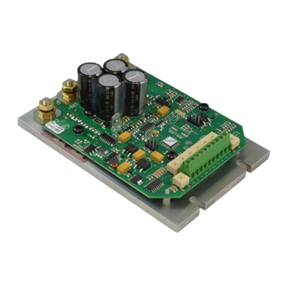
DC60-4Q
4Q PWM Microprocessor-based Chassis
Adjustable Speed Drive
for Low Voltage PMDC Brush Motors
READ ALL SAFETY WARNINGS BEFORE INSTALLING THIS EQUIPMENT
Motor
Motor
• DO NOT INSTALL, REMOVE, OR REWIRE THIS EQUIPMENT WITH POWER APPLIED. Have a
Continuous HP
Peak
•
qualified electrical technician install, adjust and service this equipment. Follow the Na�onal
Range
HP
•
Electrical Code and all other applicable electrical and safety codes, including the provisions of the
1/25 - 3/8
3/4
•
Occupa�onal Safety and Health Act (OSHA), when installing equipment.
1/12 - 3/4
1 1/2
• Avoid direct contact with the printed circuit board or with circuit elements to prevent the risk of
1/12 - 2/3
1 1/3
•
serious injury or fatality. Use a non-metallic screwdriver for adjus�ng the calibra�on trim pots. Use
1/6 - 1 1/3
2 2/3
•
approved personal protec�on equipment and insulated tools if working on this drive with power
•
applied.
• The drive is not diode-protected from reverse ba�ery voltage. You must ensure that the posi�ve
•
terminal is wired to +BAT and the nega�ve terminal is wired to -BAT.
• Reduce the chance of an electrical fire, shock, or explosion by using proper grounding techniques,
•
over-current protec�on, thermal protec�on, and enclosure. Follow sound maintenance procedures.
• Removing DC power is the only acceptable method for emergency stopping. Do not use
•
regenera�ve braking, decelera�ng to minimum speed, or coas�ng to a stop for emergency stopping.
•
They may not stop a drive that is malfunc�oning. Removing DC power is the only acceptable method
•
for emergency stopping.
• Applying and removing DC source voltage is recommended for infrequent star�ng and stopping of a
•
drive only. Regenera�ve braking, decelera�ng to minimum speed, or coas�ng to a stop is
•
recommended for frequent starts and stops. Frequent star�ng and stopping can produce high
•
torque. This may cause damage to motors.
• Do not disconnect any of the motor leads from the drive unless power is removed or the drive is
•
disabled. Opening any one lead while the drive is running may destroy the drive.
• Under no circumstances should power and logic level wires be bundled together.
• Be sure poten�ometer tabs do not make contact with the poten�ometer's body. Grounding the
•
input may cause damage to the drive.
• Do not exceed 30 in-lbs �ghtening torque on terminals.
Input Power
Connect the DC input power leads to terminals +BAT (posi�ve) and -BAT (nega�ve). Connec�ng the
DC input power backwards will cause damage to the drive.
Pre-Charge
Connect the pre-charge switch between the posi�ve ba�ery terminal and the PRE-CHARGE tab.
Closing this switch allows the power circuitry to charge without the en�re drive turning on
(ie logic is off). This prevents large in-rushes of current and sparking on the main power contacts.
Motor
Connect the DC armature leads to terminals A1 and A2. If the motor does not spin in the desired
direc�on, power down the drive and reverse these connec�ons.
PRE-CHARGE
FUSE
BATTERY
-BAT
Safety Warnings
Connections
POWER
A1
EN
ENABLE
COM
DIR
DIRECTION
+BAT
COM
BRK
STP
REGEN STOP
COM
CW
S3
S2
COM
A2
Dimensions
0.28 [7]
A1
+BAT
3.50 [89]
1.75 [44]
-BAT
0.87 [22]
A2
A
MODEL
DC60-12/24-4Q
DC60-36/48-4Q
ALL DIMENSIONS IN INCHES [MILLIMETERS]
Speed Poten�ometer
Use a 10K ohm, 1/4 W poten�ometer for speed control. Connect the counter-clockwise end of the
poten�ometer to COM, the wiper to S2, and the clockwise end to S3. If the poten�ometer works
inveresly of desired func�onality, (i.e. to increase motor speed, you must turn the poten�ometer
counterclockwise), power off the drive and swap the COM and S3 connec�ons.
Stop
Short the COM and STP terminals to regenera�vely brake the motor to zero speed. The stop circuit
bypasses the DEC trim pot. Open the COM and STP terminals to accelerate the motor to set speed.
Do not use the Stop func�on for emergency stopping.
Enable
Connect an enable switch to the COM and EN terminals. Close the switch to run and open the switch
to coast the motor to a stop. The enable comes into effect regardless of direc�on. If no switch is
desired, jumper the COM and EN terminals. Do not use the Enable func�on for emergency stopping.
Direc�on
Connect a direc�on switch to the COM and DIR terminals. Close the switch to change direc�on.
Electro-mechanical Brake
The BRK terminal supplies a voltage out to an electro-mechanical DC brake. The voltage is removed
a�er a short delay once the enable is opened, the stop switch is closed, or the speed of the motor is
set to zero. The voltage is reapplied to the BRK terminal once a run command has been received. The
voltage is equal to the input power voltage.
To BAT+
10K
SPEED
POT
5.38 [137]
4.82 [122]
0.19 [5]
1.06 [27]
DIMENSION "A" HEIGHT
1.56 [40]
2.17 [56]
LOGIC
Advertisement
Table of Contents

Related Manuals for American Control Electronics Minarik DC60-4Q Series


Summary of Contents for American Control Electronics Minarik DC60-4Q Series
- Page 1 DC60-4Q 4Q PWM Microprocessor-based Chassis Adjustable Speed Drive An American Control Electronics Brand for Low Voltage PMDC Brush Motors Specifications Safety Warnings Dimensions READ ALL SAFETY WARNINGS BEFORE INSTALLING THIS EQUIPMENT Source Armature Peak Motor Motor 5.38 [137] Voltage Voltage Range •...
- Page 2 Decelera�on (DEC): The DEC se�ng determines the �me the motor takes to ramp to a lower speed. Copyright 2019 by American Control Electronics® - All rights reserved. No part of this document may To calibrate the DEC, turn the DEC trim pot CW for a longer decelera�on �me and CCW for a shorter be reproduced or retransmi�ed in any form without wri�en permission from American Control...
Need help?
Do you have a question about the Minarik DC60-4Q Series and is the answer not in the manual?
Questions and answers