
Related Manuals for TEMPUR EASE 4.0


Summary of Contents for TEMPUR EASE 4.0
- Page 1 ® EASE 4.0 OWNER’S MANUAL Customer Service AUS. 1800 763 498 Customer Service NZ. 0800 483 6789...
-
Page 2: Table Of Contents
table of contents Safety Precautions and Usage Statements ..............1–2 Parts List . -
Page 3: Safety Precautions And Usage Statements
safety precautions and usage statements Attention: Important Safety Disclaimers Read all instructions before using your EASE ® SAVE THESE INSTRUCTIONS. complete warranty information refer to the warranty information WARNING section on pages 15-16. To reduce the risk of shock, burns, fire or injury: In-Home Use and Hospital Disclaimer: Always unplug the base from the electrical outlet before servicing The EASE... - Page 4 safety precautions and usage statements a temporary power source to get the base to a desired position. Fabric Care: Instructions on how to operate the Battery Backup Strap are on the To prolong the life of your fabric, protect from direct sunlight whenever Emergency Battery Backup page(s).
-
Page 5: Parts List
parts list Before discarding the packing materials, ensure all the parts are accounted for. All electronics and components that need to be installed are located in boxes under the base or attached to the frame. Wireless Remote Control (1) AAA Batteries (3) Mattress Retainer Bar (1)* Legs (6) Power Cord (1) -
Page 6: Base And Remote Overview
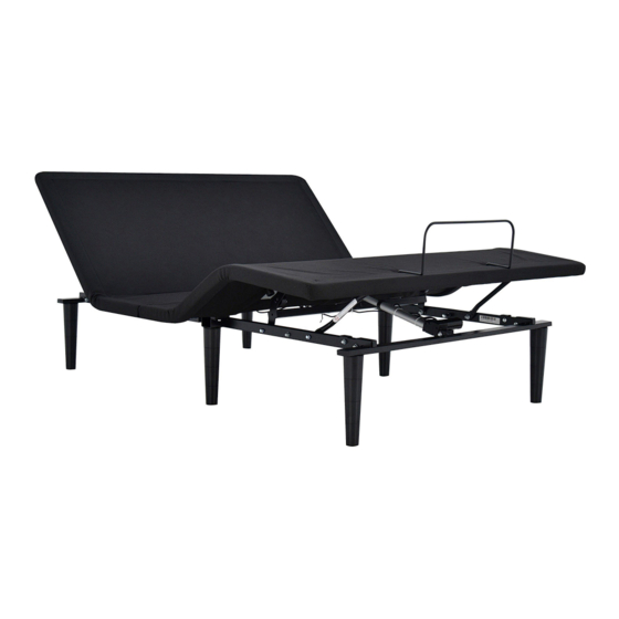
base and remote overview Actual product design may vary. Head Motor Lifts and lowers Lifts and lowers Head portion of Foot portion of the base the base Control Box Lowers head and foot por- tions of the base to FLAT preset position Zero-G ®... -
Page 7: Quick Reference Guide
quick reference guide Not to scale. For illustration purposes only. Read all instructions before beginning installation. CONTROL BOX OVERVIEW ELECTRONICS OVERVIEW Foot Motor Head Motor Power Cord Multifunction Power Cord Foot Motor Head port Port Motor Port Control Box Power Supply Input Power Cord Wireless... -
Page 8: Installation Guide
installation guide Always use two people when setting up the base. STEP 1 STEP 3 Place the bed base box in a desired location with the bottom of To install Headboard Brackets (sold separately) the box facing up. see instructions on page 12. Remove the binding straps and packing materials, making sure Legs are shipped fully assembled. - Page 9 installation guide STEP 9 STEP 5 Ensure that batteries are correctly installed in the remote. Uncoil input Power Cord (connected to Quickly test remote functions to verify proper setup before Control Box’s power port) and plug into placing mattress on base. Return the base to a FLAT position Power Supply.
-
Page 10: Remote Control
remote control Remote Control arrives paired to the adjustable base. Three (3) AAA batteries are required to operate the remote. ADJUST Head Position Adjustments (A, B) A) HEAD UP Use to raise and lower the head C) FOOT UP section of your adjustable base. button button Foot Position Adjustments (C, D) - Page 11 remote control Child Lock Feature Remote Pairing WARNING The original remote that comes in the box is already paired to the adjustable base. No further action is required. In the event Children and pets can be crushed or killed in moving parts of the bed! that the remote is not paired with the base, follow the steps For safety purposes, the child lock function locks the remote control below.
-
Page 12: Connecting Strap
connecting strap (optional) If any split setup is being installed, plastic Connecting Straps are provided (one per base) to secure the bases together. STEP 1 STEP 2 With the bases in their desired Slide side (a) of the Connecting Strap onto leg bolt. Swing the location, slightly loosen both strap and connect side (b) to the leg bolt. -
Page 13: Syncing Two Bases
syncing two bases (optional) A Sync Cord is included with the base. Not available on Queen, Full or King/Cal King size bases. The Sync Cord connects the two control boxes to a single remote for the synchronization of two bases. STEP 1 Unplug bases from power source. -
Page 14: Headboard Brackets (Not Included)
headboard bracket installation guide (optional) Headboard Brackets are an optional accessory and are not included. A hex key is included with the accessory kit to complete installation. STEP 1 STEP 2 a. Measure the distance between the mounting holes on the a. -
Page 15: Emergency Battery Backup Strap
emergency battery backup Two (2) 9 Volt batteries are required to operate the power down feature and are NOT included. STEP 1 STEP 3 Disconnect the Power Supply from the input power cord. Connect the end of the Battery Backup Strap to the input power cord that is attached to the control box. -
Page 16: Troubleshooting
troubleshooting If one or more functions on the bed base have stopped operating: ADJUSTABLE BASE • Check under the bed base to verify that the wired connections are secure and that there are no cords or bedding obstructing the movement of the base. •... - Page 17 This three (3) year warranty shall not apply In no instance will this warranty cover any damage attributable to misuse or to normal if the purchaser does not return any and all defective parts to Tempur Sealy ®...
-
Page 18: Warranty
CUSTOMER SERVICE: eligible to make a valid claim under this Warranty. If original proof of purchase is not provided by the purchaser, Tempur Sealy ® reserves Please have your receipt ready and available.
Need help?
Do you have a question about the EASE 4.0 and is the answer not in the manual?
Questions and answers