Advertisement
Table of Contents
- 1 Table of Contents
- 2 Safety Precautions and Usage Statements
- 3 Parts List
- 4 Base Overview
- 5 Quick Reference Guide
- 6 Installation Guide
- 7 Remote Control
- 8 USB Charging
- 9 Connecting Strap
- 10 Syncing Two Bases (Optional)
- 11 Headboard Brackets (Optional)
- 12 Emergency Battery Backup Strap
- 13 Troubleshooting
- 14 Warranty
- Download this manual
Advertisement
Table of Contents

Related Manuals for TEMPUR ERGO SMART


Summary of Contents for TEMPUR ERGO SMART
- Page 1 ERGO SMART ® OWNER’S MANUAL Customer Service AUS. | 1300 306 062 Customer Service N.Z | 0800 483 6789...
-
Page 2: Table Of Contents
table of contents Safety Precautions and Usage Statements ............1-4 Parts List . -
Page 3: Safety Precautions And Usage Statements
® ® In-Home Use and Hospital Disclaimer: SAVE THESE INSTRUCTIONS. The Tempur Ergo bed base is designed solely for in-home use. This base was not designed as a hospital bed and is not designed to meet hospital standards. WARNING To reduce the risk of shock, burns, fire or injury:... - Page 4 SMART POWERED BY SLEEPTRACKER-AI and void your ® ® warranty. For best performance, you should enter and exit the TEMPUR frequency energy and, if not installed and used in accordance with ERGO SMART POWERED BY SLEEPTRACKER-AI while it is in the flat or the instructions, may cause harmful interference to radio ®...
- Page 5 Most European Countries – 1 ~ 13 802.11a: ® Bluetooth SIG, Inc. and any use of such marks by Tempur Sealy International, USA – 36, 40, 44, 48, 52, 56, 60, 64, 100, 104, 108, 112, 116, 120, 124, 128, 132, 136, 140, 149, 153, 157, 161, 165 Inc.
- Page 6 This equipment was tested for FCC compliance under conditions that Designed in Santa Cruz, California included the use of Tempur peripheral devices and Tempur cables and Made in China connectors between system components. It is important that you use Tempur...
-
Page 7: Parts List
parts list Before discarding the packing materials, ensure all the parts are accounted for. All electronics and components that need to be installed are located in boxes under the base or attached to the frame. Wireless Remote Control (1) AAA Batteries (2) Mattress Retainer Bar (1)* Legs (6) Power Cord (1) -
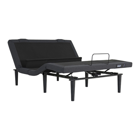
Page 8: Base Overview
To access all the features of your smart base, please download the TEMPUR SLEEPTRACKER-AI App and setup using the ® ® QR code found on the back of the remote control. Under Bed Sleeptracker-AI Control ® Light Ports... -
Page 9: Quick Reference Guide
quick reference guide Not to scale. For illustration purposes only. Read all instructions before beginning installation. Battery Remote Control Backup Strap Massage Motors Under Bed Power Supply Input Cord Power Cord Lighting USB Charging Ports Lumbar Motor Foot Motor LED Brand Badge Head Motor Control Box... -
Page 10: Installation Guide
installation guide Always use two people when setting up the base. STEP 3 STEP 1 Place the bed base box in a desired location with the bottom To install Headboard Brackets (sold separately) of the box facing up. see instructions on page 17. Remove the binding straps and packing materials, making sure Legs are shipped fully assembled. - Page 11 installation guide STEP 9 STEP 5 Ensure that batteries are correctly installed in the remote. Uncoil Input Cable (connected to Control Quickly test remote functions to verify proper setup before Box’s power port) and plug into Power placing mattress on base. Return the base to a FLAT position Supply.
- Page 12 To complete the Smart Base setup, download the TEMPUR STEP 11 ® SLEEPTRACKER-AI App and follow the in-app prompts. ® Using the remote, move the head of Once the app is connected, it will allow access to the full the base to its full upright position.
-
Page 13: Remote Control
remote control Remote control arrives paired to the adjustable base. Two (2) AAA batteries are required to operate the remote. ADJUST Head Position Adjustments Use to raise and lower the head section of your adjustable base. Foot Position Adjustments Use to raise and lower the foot section of your adjustable base. - Page 14 remote control Remote control arrives paired to the adjustable base. Two (2) AAA batteries are required to operate the remote. PRESET MASSAGE Zero-G ‡ ® Head Zone Massage Control Adjusts your legs to relieve pressure off the lower Activates simple steady-state massage and toggles back.
- Page 15 remote control Remote Pairing Child Lock Feature WARNING The original remote that comes in the box is already paired to the adjustable base. No further action is required. In the event that the remote is not paired with the base, follow the steps Children and pets can be crushed or killed in moving parts below.
-
Page 16: Usb Charging
USB Charging The USB charger is configured with 2 connectors, Type-A and Type-C connector. TYPE-A CONNECTOR (STANDARD USB) TYPE-C CONNECTOR Type-A connector standard USB port, used for standard The Type-C USB connector is a smaller cable connection interface for personal USB port. -
Page 17: Connecting Strap
connecting strap If any split setup is being installed, plastic Connecting Straps are provided (one per base) to secure the bases together. STEP 1 STEP 2 With the bases in their desired Slide side (a) of the Connecting Strap onto leg bolt. Swing the location, slightly loosen both strap and connect side (b) to the leg bolt. -
Page 18: Syncing Two Bases (Optional)
syncing two bases (optional) To sync two bases wirelessly, please refer to the below instructions. The remote controls must be paired to their respective control boxes prior to completing this step. Refer to page 13 for specific instructions. PERFORMANCE NOTES STEP 1 Unplug bases from power outlet. -
Page 19: Headboard Brackets (Optional)
headboard bracket installation guide (optional) Headboard Brackets are an optional accessory and are not included. A hex key is included with the accessory kit to complete installation. STEP 1 STEP 2 a. Measure the distance between the mounting holes on the a. -
Page 20: Emergency Battery Backup Strap
emergency battery backup strap Two (2) 9 Volt batteries are required to operate the power down feature and are NOT included. STEP 1 STEP 3 Disconnect the Power Supply from the input power cord. Connect the end of the Battery Backup Strap to the input cable that is attached to the control box. -
Page 21: Troubleshooting
• Ensure that the remote control is paired to the bed base. Sleeptracker-AI ® • For support with Sleeptracker-AI Monitor please open the TEMPUR SLEEPTRACKER-AI App and select ® ® ® Menu > Help > Contact Support or email support@sleeptracker.com If your issue is not resolved by following the instructions above, please locate the serial number on the warranty card or back of the remote control and call the customer service team for your region. - Page 22 (3) years from the warranty product, you take “as is” and “with all faults.” If you did not purchase this TEMPUR ERGO commencement date. During these first three years of the warranty, the entire product is ®...
-
Page 23: Warranty
ISSUES PERSIST, PLEASE CALL TEMPUR-PEDIC that you are the original purchaser and eligible to make a valid claim under this Warranty. CUSTOMER SERVICE: If original proof of purchase is not provided by the purchaser, Tempur-Pedic reserves the ® right to determine if the unit is covered, or is not covered, by this Warranty and may use Please have your receipt ready and available.
Need help?
Do you have a question about the ERGO SMART and is the answer not in the manual?
Questions and answers