
Related Manuals for ICP DAS USA MQ-7200M Series


Summary of Contents for ICP DAS USA MQ-7200M Series
- Page 1 Industri al Computer P roducts Data Acquisi ti on Syste ms MQ-7200M Series User Manual Written by Liam Lin Edited by Janice Hong...
- Page 2 Warranty All products manufactured by ICP DAS are under warranty regarding defective materials for a period of one year, beginning from the date of delivery to the original purchaser. Warning ICP DAS assumes no liability for any damage resulting from the use of this product. ICP DAS reserves the right to change this manual at any time without notice.
-
Page 3: Table Of Contents
Table of Contents Introduction .................... 5 Features ......................6 Overview ......................9 Dimensions (Unit: mm) ................... 10 Hardware Information ................11 MQ-7244M ...................... 11 MQ-7251M ...................... 13 MQ-7252M ...................... 14 MQ-7253M ...................... 16 MQ-7255M ...................... 17 Getting Started ..................19 Cabling Power and Network ................ - Page 4 Last Will ......................37 Publications ..................... 38 Digital Outputs....................39 Digital Inputs ....................39 Authentication ..................42 User Management ................... 42 Web HMI ....................43 Example: MQTT Publish/Subscribe I/O Status ........44 Publishing the I/O status of MQ-7200M ............44 Subscribing the I/O Status of the MQ-7200M ..........
-
Page 5: Introduction
1. Introduction The MQ-7200M series is a web-based Ethernet I/O module equipped with a built-in web server allows the user to configure module and control/monitor the status of digital I/O by simply using a regular web browser. Support for MQTT protocol makes it easy to connect sensors to Internet of Things (IoT) system via the MQ-7200M series module. -
Page 6: Features
I/O usage and enhances performance of the I/O operations. Daisy-Chain Ethernet Cabling The MQ-7200M Series has a built-in two-port Ethernet switch to implement daisy-chain topology. The cabling is much easier and total costs of cable and switch are significantly reduced. - Page 7 Dual Watchdog The Dual Watchdog consists of a Module Watchdog and a Communication Watchdog. The actions of digital output are also associated to the Dual Watchdog. Module Watchdog is a built-in hardware circuit to monitor the operation of the module and will reset the CPU if a failure occurs in the hardware or the software.
- Page 8 Reset Button The reset button is used to restore all settings to factory defaults. It is very useful especially when the user forgets the IP address to access the MQ-7200M module. Pressing and holding the reset button for at least 3 seconds will restore the module to its factory defaults. For more information, see section “7.4.
-
Page 9: Overview
1.2 Overview Connector 1 LED Indictors Reset Button I/O Indictors Connector 2 E1 Port E2 Port MQ-7200M Label Status Description Flashing The unit is turned on and ready. A link has been established on the E1 port. No link is established on the E1 port. Flashing Data is now transferred via the E1 port. -
Page 10: Dimensions (Unit: Mm)
1.3 Dimensions (Unit: mm) Top View Left Side View Front View Bottom View MQ-7200M User Manual, version 1.0.1 Page: 10... -
Page 11: Hardware Information
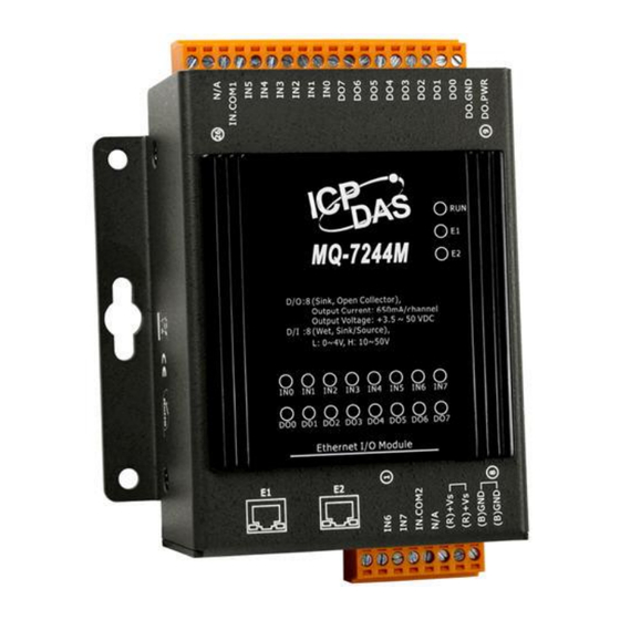
2. Hardware Information 2.1 MQ-7244M I/O Specifications Digital Input Channels Type Wet Contact Sink/Source (NPN/PNP) Sink/Source On Voltage Level +10 V ~ +50V Off Voltage Level +4 V max. Input Impedance 10 KΩ Overvoltage Protection 70 V Digital Output Channels Type Isolated Open Collector Sink/Source (NPN/PNP) - Page 12 Pin Assignments Wire Connections Digital Input Readback as 1 Readback as 0 +10 ~ +50 V Open or < 4 V Sink Source Digital Output ON State: Readback as 1 OFF State: Readback as 0 Drive Relay Resistance Load MQ-7200M User Manual, version 1.0.1 Page: 12...
-
Page 13: Mq-7251M
2.2 MQ-7251M I/O Specifications Digital Input Channels Type Wet Contact Sink/Source (NPN/PNP) Sink/Source On Voltage Level +10 V ~ +50V Off Voltage Level +4 V max. Input Impedance 10 KΩ Overvoltage Protection 70 V Pin Assignments Wire Connections Digital Input Readback as 1 Readback as 0 +10 ~ +50 V... -
Page 14: Mq-7252M
2.3 MQ-7252M I/O Specifications Digital Input Channels Type Wet Contact Sink/Source (NPN/PNP) Sink/Source On Voltage Level +10 V ~ +50V Off Voltage Level +4 V max. Input Impedance 10 KΩ Overvoltage Protection 70 V Digital Output Channels Type Isolated Open Collector Sink/Source (NPN/PNP) Source Max. - Page 15 Wire Connections Digital Input Readback as 1 Readback as 0 +10 ~ +50 V Open or < 4 V Sink Source Digital Output ON State, Readback as 1 OFF State, Readback as 0 Source MQ-7200M User Manual, version 1.0.1 Page: 15...
-
Page 16: Mq-7253M
2.4 MQ-7253M I/O Specifications Digital Input Channels Type Dry Contact Sink/Source (NPN/PNP) Source On Voltage Level Close to GND Off Voltage Level Open Overvoltage Protection Effective Distance 500 M Max. Pin Assignments Wire Connections ON State: Readback as 1 Digital Input OFF State: Readback as 0 Dry Contact MQ-7200M User Manual, version 1.0.1... -
Page 17: Mq-7255M
2.5 MQ-7255M I/O Specifications Digital Input Channels Type Dry and Wet Contact Dry: Source Sink/Source (NPN/PNP) Wet: Sink/Source On Voltage Level +10 V ~ +50 V Wet Contact Off Voltage Level +4 V max. On Voltage Level Close to GND Dry Contact Off Voltage Level Open... - Page 18 Wire Connections Digital Input Readback as 1 Readback as 0 +10 ~ +50 V Open or < 4 V Wet Contact (Sink) Wet Contact (Source) Digital Input ON State: Readback as 1 OFF State: Readback as 0 Dry Contact Digital Output ON State: Readback as 1 OFF State: Readback as 0 Source...
-
Page 19: Getting Started
3. Getting Started If the user is new to using the MQ-7200M module, start with this chapter as it includes a guided tour that provides a basic overview of how to install, configure and use the module. What’s in the BOX? Before starting any task, please check the package contents. -
Page 20: Cabling Power And Network
Cabling Power and Network Step 1: Connect the computer to the Ethernet Port via the Hub or Switch. Step 2: Connect the positive of the power supply to the terminal marked “(R)+Vs”. Connect the negative of the power supply to the terminal marked “(B)GND”. Host PC Power Supply Hub/Switch... -
Page 21: Installing The Minios7 Utility
3.2 Installing the MiniOS7 Utility The MiniOS7 Utility provides a quick and easy way to configure the Ethernet settings, update OS image or firmware file to the MQ-7200M from a computer. After the installation has been completed, a new shortcut for the MiniOS7 Utility will be displayed on the desktop. Step 1: Install the MiniOS7 Utility tool The latest version of the MiniOS7 Utility can be obtained from the ICP DAS website:... -
Page 22: Configuring Network Settings
3.3 Configuring Network Settings The MQ-7200M comes with default network settings as the table below. Before starting the MQ-7200M, valid network settings for the LAN where the module will operate need be set to the module. Default Ethernet Settings Item Default IP Address 192.168.255.1... - Page 23 Step 2: Click the menu "Connection > Search" (or press the "F12" key) to search for the module. Check the status bar to monitor for the progress of the search Step 3: Click the “192.168.255.1” in the IP/Port field and click the “IP Settings” button Click the item you want to configure (the default IP= “192.168.255.1”) and then click the “IP Settings”...
- Page 24 Step 4: Specify the appropriate IP/Mask/Gateway address In the IP Settings dialog box, the user can manually specify the IP, Mask, Gateway addresses, and alias. Alternatively, the user can enable the DHCP Client function to dynamically obtain an IP address from the DHCP Server. After entering the appropriate values, click the "Set" button to update the configuration.
-
Page 25: Logging In To Web Interface
3.4 Logging in to Web Interface The MQ-7200M series module provides a web-based user interface that allows users to manage the module, access I/O, and monitor the running status through a standard web browser. Step 1: Launch the browser The user can use a standard web browser such as Mozilla Firefox or Internet Explorer to log in to the MQ-7200M module. - Page 26 Step 4: Welcome to the MQ-7200M web interface After logging into the module, the Overview page provides a brief description of the module, including its MAC address, the current firmware version, and other relevant information. MQ-7200M User Manual, version 1.0.1 Page: 26...
-
Page 27: Configuration
4. Configuration The web-based user interface allows users to configure the module, access and monitor the I/O status through a web browser. Before starting the configuration steps, please refer to Chapter 3 - Getting Started to configure and log in to the MQ-7200M module. Step 1: Welcome to the MQ-7200M web interface After logging into the MQ-7200M web interface, the user will see relevant information about... -
Page 28: Basic Settings
4.1 Basic Settings The Basic Settings page includes Network Configuration and Basic Settings sections. Network Configuration In the Configure dropdown menu, there are two ways to configure the network: ● Manual configuration – Manually: If DHCP is not available, you can manually set up the IP address, subnet mask, and gateway addresses for the MQ-7200M module. - Page 29 In general, network settings include the following parameters: ● IP address: Each MQ-7200M module needs to be configured with a unique IP address to log in to the module's settings page on the network. ● A subnet mask: The subnet mask indicates which portion of the IP address that is used to identify the local network or subnet.
-
Page 30: Basic Settings
Basic Settings This section includes the following items: ● Module Name: The initial value for this field will depend on the model of the module and cannot be modified. ● Page Header Information (First line) and Page Header Information (Second line): The title of the website that is displayed at the top left-hand corner of the interface, for example the company name and web address as per the example below. -
Page 31: I/O Settings
4.2 I/O Settings In industrial applications, maintaining a "safe" state for the module's output when power is restored after a power loss caused by either a normal or abnormal event is crucial to prevent accidents. In addition, in the case of host failure or network communication exceptions, it is equally important to output a safety value. -
Page 32: Power-On Value
Power-on Value The user can set the power-on value for each output channel. When the module is powered on normally or reset by the module watchdog, it loads its power-on value. Method: After selecting On or Off, clicking the Apply button to complete the setting. Safe Value The user can set the safe value for each output channel. -
Page 33: Mqtt
4.3 MQTT MQTT is a Client Server publish/subscribe messaging transport protocol. It is light weight, open, simple, and designed so as to be easy to implement. These characteristics make it ideal for use in many situations, including constrained environments such as for communication in Machine to Machine (M2M) and Internet of Things (IoT) contexts where a small code footprint is required and/or network bandwidth is at a premium. -
Page 34: Mqtt Conversation
On the MQTT page, the user can enable/disable the MQTT function, set the broker information, define the Last Will and Testament for announcing a module’s offline message, and obtain the topic names for each I/O. MQTT conversation The user can enable/disable the MQTT function. If the MQTT conversation is disabled, the module will stop publishing messages. -
Page 35: Connectivity
Connectivity The user can customize the settings related to the Broker and the connection, and if any changes are made, click the Apply button. Item Description Enter the Broker URI and port for MQTT connection. Broker URI The Broker URI can be an URL or an IP address. The identifier for each MQTT Client to connect to the MQTT Broker Client identifier must be unique. -
Page 36: Security
Reconnection interval In the event of a connection failure, how long does the MQ-7200M (Unit: second) wait before attempting to reconnect to the Broker? The Keep-alive mechanism ensures the availability of both the Client and the Broker for communication purposes. If the Client has no message to send within the specified Keep Alive Interval, it is required Keep alive interval to send a PINGREQ packet to the Broker, while the Broker must reply... -
Page 37: Last Will
Last Will The Last Will and Testament (LWT) function notifies other clients when a client disconnects abnormally. The MQ-7200M can retain the Last Will (LWT) message on the Broker. If the MQ-7200M unexpectedly disconnects, the Broker will send the LWT message to all clients that have subscribed to this Offline topic. -
Page 38: Publications
In the publisher/subscriber model, once subscribe to a topic (or I/O channel), the subscriber can receive the information (status) related to that topic. The publisher can periodically send its content to all subscribers of the topic, or whenever there is new information available. Publications The I/O status can be published to topics based on either a time-driven or event-driven approach. -
Page 39: Digital Outputs
The user can customize the topic name and published conditions for each I/O. If the MQTT conversation feature is enabled, the MQ-7200M will automatically subscribe to all DO topics upon startup. Digital Outputs Digital Inputs A topic for each I/O channel on a MQ-7200M module consists of 3 topic levels; each topic level is separated by a forward slash (/): For example F001/GetValue/DO1... - Page 40 Level 1: The default is the name specified in the “Connectivity - Client identifier” field. Level 1 Client identifier The default is the module name followed by the MAC address. 可自訂第 1 層的主題名稱。 Topic prefix Level 2: To get or set the I/O status Level 2 Subscribed topic: The MQTT client will send a message to control the SetValue...
- Page 41 The DO operation can be divided into two steps, for example, the steps to turn off the lights (DO1) are as follows: Topic: F001/Set_Value/DO_1 DO1 = 0 MSG: 0 Published msg. : (Turn the light off) Turn off the lights MQTT Broker MQTT Client MQTT Client...
-
Page 42: Authentication
5. Authentication To ensure secure access to the MQ-7200 web interface, authentication is implemented as a requirement. When attempting to connect to the web interface, users are prompted to provide both a username and password. Authentication is enabled by default. User Management The factory default employs the administrator account, and you can establish an additional administrator or user account. -
Page 43: Web Hmi
6. Web HMI On this Web HMI page, the user can get the following information: 1. Connection status between the PC and the MQ-7200M module, 2. Connection status between the MQ-7200M module and the broker you set, 3. The status of each I/O channel. The user can control the output channels by clicking the On or Off button. -
Page 44: Example: Mqtt Publish/Subscribe I/O Status
7. Example: MQTT Publish/Subscribe I/O Status 7.1 Publishing the I/O status of MQ-7200M Publish MQTT Client MQTT Broker 1. On the MQTT page, make sure that the MQTT function is enabled. 2. Enter both the URL and port number of the Broker, and click the Apply button to update the settings. - Page 45 3. On the Basic Settings page, make sure that the DNS Server has been configured properly. 4. On the Web HMI page, the user can verify if the connection is successful. Connection Status: = Good, = Disconnection If the connection between the MQ-7200M and the MQTT broker is established successful, all the topics listed on this page will be published to the Broker.
-
Page 46: Subscribing The I/O Status Of The Mq-7200M
7.2 Subscribing the I/O Status of the MQ-7200M Subscribe MQTT Client MQTT Broker MQTT Client Before proceeding with the testing of the I/O subscription function, it is essential to install the MQTT client on your PC. MQTT Lens is a Chrome extension tool that lets you publish messages to an MQTT broker, subscribe to MQTT topics, and receive messages using the chrome web browser. - Page 47 3. Click the "+" button to add a connection, enter a name (e.g., Broker01) in the Connection Name field, enter a hostname (e.g., broker.hivemq.com) in the Hostname field, and click the “Create Connection” button. 4. Enter the topic in the Subscribe field and click the button. MQ-7200M User Manual, version 1.0.1 Page: 47...
- Page 48 5. The user can all topics listed on the Web HMI page to the subscriptions. Next, click the ON/OFF button to change the status of the I/O, and view the subscribed messages. Change the status of the I/O View the subscribed messages MQ-7200M User Manual, version 1.0.1 Page: 48...
-
Page 49: Controlling The Do Status Of The Mq-7200M
7.3 Controlling the DO Status of the MQ-7200M Topic: F001/Set_Value/DO_0 DO1 = 0 Message: 1 (Turn the light on) (Publish: D00 = ON) MQTT Broker MQTT Client MQ-7200M 1. Ensure that the MQTT function is enabled and the broker is correctly configured on the MQTT page of the MQ-7200M module. - Page 50 5. In the Publish field of the MQTT Lens, enter the Topic name (F001/Set_Value/DO_0) and the Message (1), and then click the “Publish” button. Now, the user can observe that the DO0 indicator of the MQ-7200M has been switched on, and the status of DO0 on the Web HMI page reflects as "ON."...
-
Page 51: Frequently Asked Question (Faq)
8. Frequently Asked Question (FAQ) Establishing a Connection by Using MiniOS7 Utility MiniOS7 Utility is a tool for uploading firmware to flash memory and updating the OS to the MQ-7200M module embedded with MiniOS7 with easiness and quickness. If the MiniOS7 Utility is not yet installed on the system, installation of the MiniOS7 Utility should be the first step. - Page 52 Step 2: Press the “F12” key or choose the “Search” option from the “Connection” menu After pressing the “F12” key or choosing the “Search” option from the “Connection” menu, the MiniOS7 utility performs a search of all modules on the network. Check the status bar to monitor the progress of the search.
- Page 53 Step 4: Check the connection symbol to make sure that the connection is established Check the connection symbol status in the top right side to make sure the connection has been established. Connection Status : Connected : Disconnected MQ-7200M User Manual, version 1.0.1 Page: 53...
-
Page 54: Exchanging The Protocol (Tcp/Ip To Udp)
8.2 Exchanging the Protocol (TCP/IP to UDP) MiniOS7 Utility supports both UDP and TCP protocols. For MiniOS7 Utility, the TCP/IP is the default protocol for communicating with MQ-7200M, and the UDP is used to update the OS. Hence, if the user wants to update the operating system, please change the communication protocol to UDP. -
Page 55: Updating The Mq-7200M Os
8.3 Updating the MQ-7200M OS Additional features to MQ-7200M OS will continue to be added in the future, so we advise the user to periodically check with ICPDAS web site for the latest updates. The latest version of the OS image can be obtained at: http://www.icpdas.com/en/download/show.php?num=2678 Release Date Protocol Type... - Page 56 Step 3: Select the latest version of the MiniOS7 OS image After choosing the update MiniOS7 Image command, a dialog box titled "Select MiniOS7 Image file" will appear. Please select the most recent version of the MiniOS7 OS image. Step 4: Click “OK”...
-
Page 57: Using The 7188Eu.exe And Command Line
8.3.2 Using the 7188EU.exe and Command Line Step 1: Establish a connection to MQ-7200M. Be sure that the MiniOS7 Utility is connecting with the MQ-7200M using the UDP connection. For a more detailed description of this instruction, refer to the section “8.2. Exchanging the Protocol (TCP/IP to UDP)”. - Page 58 Step 4: Upload the MiniOS7 image Press Enter to see “ET7K_UDP>” in the window and input the upload command, then press Enter. Also, press ALT + E and enter the full name of the image file (e.g., ET7200_UDP_20161124.img) Press Enter after inputting the command. If no files are uploaded, confirm that both the IP addresses of the PC and the module are on the same network segment.
-
Page 59: Updating The Mq-7200M Firmware
8.4 Updating the MQ-7200M Firmware The firmware is stored in flash memory and can be updated to fix functionality issues or add additional features, so we advise the user to periodically check the ICP DAS web site for the latest updates. - Page 60 Tips & Warnings The user has to delete all files existed on the MQ-7200M before uploading the firmware. Step 3: In the Confirm dialog box, click the “Yes” button to continue. After executing the Erase Disk command, the Confirm dialog will appear, and then click “Yes” button to continue erasing the memory contents.
- Page 61 Step 5: Reboot the module. After the update is completed, reboot the module. MQ-7200M User Manual, version 1.0.1 Page: 61...
-
Page 62: Restoring The Mq-7200M To Default Settings
8.5 Restoring the MQ-7200M to Default Settings If the network configuration on the MQ-7200M is lost, press and hold the reset button for at least 3 seconds can restore the MQ-7200M to default factory settings. Reset Button The following configuration will be restored: Network Configuration Item Factory Default Settings... -
Page 63: Modbus Register Table
9. Modbus Register Table Coils (0xxxx) Register Factory Points Description Settings Attribute Value 00000 0000 0: Off DO value 1: On 00005 0005 Clear 1-ch historical DI max. value 00032 0020 1: Clear Clear 1-ch historical DI min. value 00033 0021 1: Clear 00064... - Page 64 Input Register (3xxxx) Register No. Per Points Description Data Format Attribute Point Number of the DI channel 30100 0064 Number of the DO channel 30110 006E OS image version 30150 0096 0x123 means version 1.2.3 Firmware version 30151 0097 0x123 means version 1.2.3 I/O version 30153 0099...
-
Page 65: Troubleshooting
10. Troubleshooting A number of common problems are easy to diagnose and fix if the user knows the cause. Symptom/Problem Possible cause Solution The Run LED doesn’t light Internal power has failed Return the module for repair. The Run LED indicator is ON The module has possibly Reboot the module (light), but not flashing. -
Page 66: Revision History
Revision History The table below shows the revision history. Revision Date Description 1.0.0 Aug, 2016 Initial issue Adjust the order of chapters, add or modify some chapter content 1.0.0 Jun, 2023 and screenshots. MQ-7200M User Manual, version 1.0.1 Page: 66...
Need help?
Do you have a question about the MQ-7200M Series and is the answer not in the manual?
Questions and answers