
Related Manuals for Amazone UF 600


Summary of Contents for Amazone UF 600
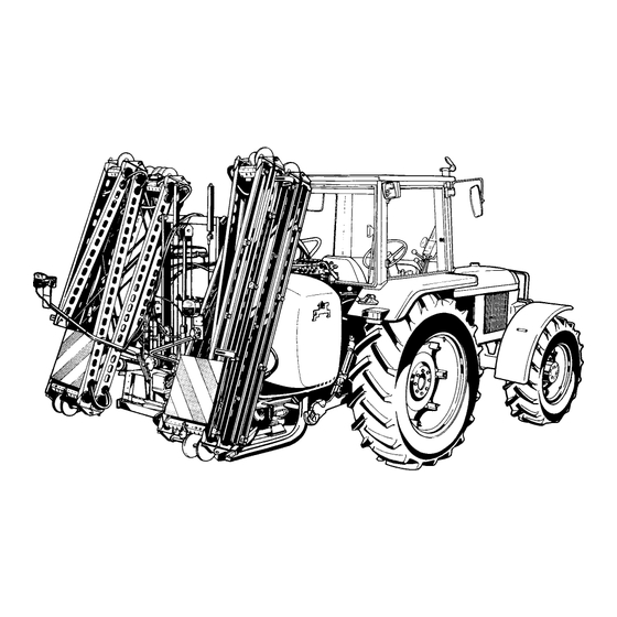
- Page 1 Instruction manual Mounted Sprayer UF 600 UF 800 UF 1000 UF 1200 MG 370 SB 233.2 (GB) 04.03 Printed in Germany Before starting operation carefully read and adhere to this instruction manual safety advice.
- Page 2 Reading the instruction manual and to adhere to it should not appear to be in- con-venient and superfluous as it is not enough to hear from others and to realise that a machine is good, to buy it and to believe that now everything would work by itself.
- Page 3 Preface Preface Dear Customer, the mounted sprayer UF is yet another high quality product from the large range of farm ma- chinery manufactured by AMAZONEN-WERKE, H. Dreyer GmbH & Co. KG. In order to make fullest use of your trailed sprayer and to ensure trouble-fee operation, we recommend that this instruction manual is carefully read and that the content is observed and the advice given therein is ad- hered to.
-
Page 4: Table Of Contents
Table of contents Details about the machine..................9 Range of application..........................9 1.1.1 Designated use of the machine......................9 1.1.2 Designated equipment of the crop protective implement...............9 Attention when using specific crop protection agents ................10 Manufacturer ............................10 Conformity declaration .........................10 On requesting after sales service and parts..................10 Type plate.............................10 Safety ........................ - Page 5 Table of contents On receipt of the machine..................34 First fitting of the switch box.........................34 4.1.1 Main console, bracket and top hat profile rail ..................34 4.1.2 Battery link up cable..........................34 4.1.3 Electric switch box..........................35 4.1.3.1 On-board computer "AMACHECK II A", "SPRAYCONTROL II A" or "AMATRON II A" ......35 PTO-shaft .............................36 4.2.1 Initial fitting and matching up of the PTO shaft ..................36...
- Page 6 Table of contents Sprayer booms ...................... 63 P-boom in package folding technique, rigid booms, manually folded including manual winch for height adjustment ..........................63 8.1.1 Manual winch adjustment........................63 Q-booms and Q-plus-booms ........................64 8.2.1 Q-booms up to 8 m working width (incl. swing compensation and hydraulic height adjustment)..64 8.2.1.1 Q-boom, manually folded ........................65 8.2.1.1.1 Folding the boom in or out........................66...
- Page 7 Table of contents Maintenance, repair- and care-work ..............114 Check list for maintenance work ......................114 Cleaning the filter tap .........................115 Pump - Maintenance-, cleaning- and remedy in case of malfunction ..........116 9.3.1 Checking oil level ..........................116 9.3.2 Oil change ............................116 9.3.3 Cleaning .............................117 9.3.4...
- Page 8 Table of contents 10.20 Induction bowl with canister flushing ....................139 10.20.1 Inducting liquid agents........................139 10.20.2 Inducting powdered agents and urea....................140 10.20.3 Flushing of spray agent containers with the aid of the can wash nozzle ...........140 10.21 Induction bowl with power injector and canister flushing ..............141 10.21.1 Inducting liquid agents........................141 10.21.2 Inducting powdered agents and urea....................142 10.21.3 Flushing of spray agent containers with the aid of the can wash nozzle ...........143...
-
Page 9: Details About The Machine
Under "designated use" also the manufacturer's pre- scribed operation, maintenance and repair conditions must be adhered to as well as the exclusive use of original AMAZONE spare parts. Any damage resulting from arbitrary changes on the machine rule out the responsibility of the manufac- turer. -
Page 10: Attention When Using Specific Crop Protection Agents
In case of spraying such aggressive crop protection Using non-original spare parts will rule agents it is recommended to apply them onto the field out the liability of AMAZONE for result- immediately after the mixing with water and after- ing damage. -
Page 11: Safety
Safety Safety 2.3.2 Attention symbol Attention symbols which may cause dangers to the This instruction manual contains basic advice, which machine and it's function when not being adhered to, has to be observed when mounting, operating and are identified with the attention symbol. maintaining the machine. - Page 12 Safety MD 085 MD 089 MD 078 MD 095 MD 094 Fig. 1 Fig. 2 MD 078 MD 078 MD 094 MD 078 MD 089 MD 084 Fig. 3 UF SB 233.2 - 04.03...
- Page 13 Safety Picture No.: MD 095 Explanation: Before commencing operation read thoroughly opera- tors manual and safety advice. Picture No.: MD 078 Explanation: Never enter into bruising zones without first isolating any further movement. Picture No.: MD 084 Explanation: Never stay within the operating area of the fold- ing/unfolding sprayer booms.
-
Page 14: Safety Conscious Operation
Safety 11. When attaching or removing the machine bring Safety conscious operation any parking or storing devices into the corre- sponding position (standing safety). Besides the safety advice in this instruction manual additionally, the national, and generally valid opera- 12. Fit weights always to the fixing points provided tion safety and accident prevention advice of the and as advised for that purpose. -
Page 15: Means For Traffic Safety
Safety 16. The adjustment of loaded draw bars should 2.6.2 Means for traffic safety always be conducted under suitable workshop conditions. 1. Before starting to travel on public roads check function of brakes. 17. On single axle trailers beware of the weight re- duction on the tractor front axle and the influ- 2. -
Page 16: Hydraulic System
Safety 12. Always stop PTO when it is not needed or when 8. Before starting to do repair work to the hydraulic the shaft is in an adverse position! system release the pressure, lower machine to the ground and stop tractor engine! 13. -
Page 17: General Safety And Accident Prevention Advice For Maintenance, Repair And Cleaning
Using original AMAZONE spare parts for example ensures this. Non original parts invalidate warranty and contravene these Consider the compatibility of spray a- documentation for safe use. -
Page 18: Product Description
Product description Product description The mounted sprayer UF has been designed for fit- ting to the rear three point hydraulics of the tractor. Fig. 4 Fig. 5 Fig. 4/... or Fig. 5/... 1 - Tank with intensive hydraulic agitation system 2 - Tank level indicator Tank volume [l] = indicated scale figure x 100 3 - Tank access lid... -
Page 19: Liquid Flow Uf
Product description Liquid flow UF Suction side - Operational pump Pressure side – Operational pump Injector – Suction side Return flows Clear water system Fig. 6 Fig. 6/... 1 - Spray agent tank 15 - Internal tank wash with rotating nozzles 2 - Pump 16 - Fresh water flushing tank 3 - filter tap... -
Page 20: Control Units
Product description Control units 3.2.1 Control units, manually actuated 3.2.1.1 Control unit "B" Fig. 7 Fig. 7/... 1 - Volume control for a constant spray rate [l/ha] 9 - Equal pressure control. within one tractor gear. 10 - Equal pressure part width shut off valves for 2 - Star knob for setting and adjusting the spray switching on and off individual part width shut pressure. -
Page 21: Control Units, Remote Controlled Via Switch Box
Product description 3.2.2 Control units, remote controlled via switch box Electric switch box SKS 50/70 Functions for Super-S- booms Control units w.o. control computer with control computer UF SB 233.2 - 04.03... -
Page 22: Control Unit "F" And "G", Remote Controlled Via Switch Sks 3 Or 2, Suitable For Combinations With Functions Of The Super-S-Boom
Product description 3.2.2.1 Control unit "F" and "G", remote con- trolled via switch SKS 3 or 2, suitable for combinations with functions of the Su- per-S-boom The control unit "G" is suitable for the use with the control computers AMACHECK SPRAYCONTROL II A and AMATRON II A. - Page 23 Product description 15 - Knurled thumb knobs for setting the equal pres- sure valves. Set up the equal pressure control units via the setting screw before the first operation and after every change of noz- zles. 16 - Equal pressure valve chest return flow. When switching off one boom section the volume of spray agent that was being supplied to this sec- tion is returned via the equal pressure return...
-
Page 24: Switch Boxes Sks
Product description Switch boxes SKS 3.3.1 Elektic switch boxes SKS 50 / 70 3.3.1.1 Electric switch box SKS 50 Auto Fig. 10 Fig. 10/... 1 - Switch box SKS 50. For first fitting the switch box, please 2 - On- and off switch for the power supply. In posi- refer to chapter "Machine installation". -
Page 25: Switch Box Sks 50 With Integrated Electric Boom Tilt Control
Product description 3.3.1.2 Switch box SKS 50 with integrated elec- tric boom tilt control Fig. 11 Fig. 11/... 1 - Switch box SKS 50 N. 8 - Indicator lights (green). When the part width 2 - On- and off switch for the power supply. In posi- section has been switched on the relevant indi- tion "1"... -
Page 26: Switch Box Sks 3 With Profi Folding For Super-S- And Q-Plus- Booms
Product description 3.3.1.3 Switch box SKS 50 with Profi folding for Super-S- and Q-plus- booms Auto Fig. 12 Fig. 12/... 1 - Switch box SKS 50 HAD. 9 - Holder for fertiliser proof pressure gauge. 2 - On- and off switch for the power supply. In posi- 10 - Electro-hydraulic boom tilt adjustment. -
Page 27: Amacheck Ii A
Product description AMACHECK II A "AMACHECK II A" fastens directly on top of the switch box. "AMACHECK" is only a pure information and monitoring device and contains the following functions: • Displays the actual operational speed [km/h] and actual spray rate [l/ha]. •... -
Page 28: Filter Equipment
Product description Filter equipment Only if the spray mixture is thoroughly filtered can a trouble free operation of the sprayer, espe- cially of the nozzles be ensured and thus the filter influences considerably the success of the treat- ment. Therefore always use all filters provided and check their function through regular mainte- nance. -
Page 29: Self Cleaning The Pressure Filter Of The
Product description 3.6.2 Self cleaning the pressure filter of The pressure filter (Fig. 15/ 1) has a larger number of meshes per inch than the suction filter insert in the filter tap. This way the undesirable large particles that still remain in the spray liquid are filtered off protect- ing the nozzle filters in the spray nozzles. -
Page 30: Intensity Hydraulic Agitator
Product description Intensity hydraulic agitator Fig. 16/... 1 - Step tap for the adjustable intensity hydraulic agitation. The agitation can be set in 6 steps "0, 1, 2, 3, 4, 5". In position "0" agitation is switched off whereas the highest intensity agitation is a- chieved in position "5". -
Page 31: Clean Water Tank With Integrated Vario-Control
Product description Clean water tank with integrated Vario-control The clean water tank contains water without chemical contact. By actuating the Vario control this water can be used to dilute the spray agent residue in the tank. to clean the entire sprayer in the field (rinsing), even with the tank filled with spray agent tank. -
Page 32: Pump Outfit Diaphragm Pump 105, 115, 140, 160, 180 And 210 L/Min
Product description Pump outfit diaphragm pump 105, 115, 140, 160, 180 and 210 l/min The pumps (Fig. 19) are piston diaphragm pumps with a capacity of each 140, 160, 180, 210, 180 and 210 l/min. All components which come into contact with spray agents have been made from injection moulded plastic coated aluminium or entirely from plastic. -
Page 33: Triple Nozzle Body (Special Option)
Product description 3.10.1 Triple nozzle body (special option) When using a variety of nozzles we recommend the use of triple or three way nozzle bodies (Fig. 21). In the triple nozzle body the vertically positioned nozzle is fed. By swivelling the triple nozzle body to the right or left hand side or by turning counter clockwise an- other nozzle is brought into the operational position. -
Page 34: On Receipt Of The Machine
On receipt of the machine On receipt of the machine When receiving the machine check that no damage has been caused in transit and all parts are present. Only with the immediate reporting of damage to- wards the forwarder will be considered for compen- sation. -
Page 35: Electric Switch Box
On receipt of the machine 4.1.3 Electric switch box Slide the SKS-switch box (Fig. 23/1) into the gui- de key way of the hat profile rail (Fig. 23/2) and tighten the clamping screws. The on/off switch (Fig. 23/3) for the elec- tric power supply of the switch box should be in position "0"... -
Page 36: Pto-Shaft
On receipt of the machine PTO-shaft Only use the Walterscheid WWE 2280 PTO shaft provided. Clean and grease the tractor PTO-shaft. Slide the tractor PTO shaft halves onto the PTO and the pump input shaft in the prescribed fitting direction. When fitting initially or when chang- ing the tractor the PTO length should checked be matched to the tractor. -
Page 37: Adjustable Mounting Bracket For Control Units
On receipt of the machine 1. Check whether the overlapping of the universal joint shaft's profile tube is in any position of the sprayer behind the tractor at a minimum of 40 % of LO (length in the totally retracted position) by holding the two mounted PTO shaft tubes next to one another. -
Page 38: Hitching Up Or Off
The lower link arms of the tractor are connected to the lower link pins (cat. I or II at UF 600 or cat. II at UF 800, UF 1000 and UF 1200). Fit top link with mounting pins (cat. I or II at UF 600 or cat. -
Page 39: Traffic Lights
Hitching on or off Traffic lights Super-S-boom with Profi folding Connect the pressure hydraulic hose to a single Connect the power cable of traffic lights on tractor acting spool valve, the return hydraulic hose to a and check function of the traffic lights before eve- pressure-free return socket on the tractor. -
Page 40: En Route To The Field - Transport On Public Roads And Ways
En route to the field - Transport on public roads and ways En route to the field - Transport on public roads and ways Please adhere to the following hints. They help to prevent accidents in public traffic. When travelling on public roads and highways during transport to the field the specification of tractor and imple- ment have to correspond to the national... -
Page 41: Calculating The Payload
En route to the field - Transport on public roads and ways Calculating the payload Payload [kg] = allowable total weight [kg] - net weight [kg] The net weight depends on the execution of the im- plement. You may take it from the type plate or de- termine the net weight by adding the weight of the individual components with the aid of the para. -
Page 42: Putting Into Operation
Putting into operation Putting into operation Before the first operation set up the e- Careful calculating and metering the qual pressure control unit (refer to para. required final fill should be conducted 7.2). prior to spraying the remaining area. To achieve this deduct the technically undi- Condition for an appropriate application luted quantity of liquid within the... -
Page 43: Calculating The Filling Or Refilling Quantities
Putting into operation 7.1.1 Calculating the filling or refilling quantities Example 1: Known data: Tank nominal volume 1000 l Residual amount in tank required rate of water 400 l/ha Spray agent requirement per ha Agent A 1,5 kg Agent B 1,0 l Question: How many litres of water, how many kg of agent A... - Page 44 Putting into operation Calculation formula and reply to question 2: available spray mixture [l] - residual amount [l] = area to be sprayed [ha] required rate of water [l/ha] 1000 [l] (tank nominal volume) - 20 [l] (residual amount) = 1.96 [ha] 500 [l/ha] required rate of water UF SB 233.2 - 04.03...
-
Page 45: Filling With Water
Putting into operation 7.1.2 Filling with water Observe permissible payload! For this bear in mind the individual weights [kg/l] for the various liquid a- gents. Liquid Water Urea NP-Dilution density [kg/l] 1.11 1.28 1.38 Before refilling check the implement for any damage, e. - Page 46 Putting into operation Always use the filling sieve (Fig. 29/1) when filling the spray agent tank. Fig. 29 Read the tank volume off the pointer position on the scale (Fig. 30/1) of the tank level indicator (Fig. 30/2). Tank volume [l] = indicated scale figure x 100 Close the filling opening with the aid of the hinged cover or screw lid.
-
Page 47: Inducting Spray Agents
Putting into operation 7.1.3 Inducting spray agents If the urea filter (option) is placed into the tank sump the quantity of urea nee- ded for one tank filling can be placed directly into the tank opening. Before starting spraying operation dilute urea completely by pumping the spray cocktail around the tank. -
Page 48: Setting The Equal Pressure Control Chest Before The First Operation And After Any Change Of Jets
Putting into operation Setting the equal pressure con- trol chest before the first opera- tion and after any change of jets Set the pressure relief valve. Turn the adjustment nut (Fig. 32/1) of the auto- matic metering unit until a spacing of 5 mm is reached between the edge of the adjustment nut and the return flow hose (Fig. -
Page 49: Spraying Crop Protection Liquid
Putting into operation Spraying crop protection liquid Before the spraying season begins and All mentioned spray rates in l/ha for noz- after any change of nozzles the proper zles in the spraying table refer to water. spraying ability of the sprayer should be The corresponding figures should be checked by a calibration test (please multiplied by 0.88 for urea suspensions... -
Page 50: Hints Regarding The Slip Clutch Of The
Putting into operation Example : In case the spray pressure has been set to 3.2 bar, spray pressures between 2.4 and 4.0 bar are per- missible. At no time, however, should the maximum permissible pressure range of the nozzles fitted be exceeded. -
Page 51: Setting The Spray Rate [L/Ha]
Putting into operation 7.3.4 Setting the spray rate [l/ha] The spray rate depends on: The liquid delivery of the nozzles [l/min]. The nozzle size and the spray pressure influence the delivery of the nozzle. The spray pressure to be set is taken from the spray table depending on the type of nozzle and size. -
Page 52: Set The Spray Pressure
Putting into operation 7.3.4.2 Set the spray pressure Pre-condition for a correct spray pres- sure setting is to start with a correctly set equal pressure control chest. Turn On/Off-switch (Fig. 36/1) for the power sup- ply to position "I" (EIN) (only with control units "electrically remote controlled with switch box). -
Page 53: Calibrating
Putting into operation Calibrating Measure on the field accurately a distance of Always calibrate the sprayer with the spray pres- 100 m. Mark the starting and end point. sure set according to the spray rate table: Read off the tractor clock for which tractor gear before the beginning of any seasonal operation. -
Page 54: Stationary Calibrating From Single Nozzle Output
Putting into operation 7.4.1.2 Stationary calibrating from single nozzle output The calibrating can also be conducted by measuring 2. Read the actual liquid amount [l/ha] off the the single nozzle output (l/min) with water when the spraying table for forward speed of the tractor on the field is exactly Nozzle size '06', known. -
Page 55: Determining The Actual Operation Speed
Putting into operation Determining the actual operation speed 100 m 5 km/h = 72 s for 100 m Measure on the field accurately a distance of 100 m. Mark the starting and end point. Read off the tractor clock for which tractor gear will allow a forward speed of 6 to max. -
Page 56: Practical Operation With "Amacheck Ii A
Putting into operation Practical operation with "AMACHECK II A" The control units are supplied ready for operation. starting field operation programme "AMACHECK II A" according to the mounting and operation instructions "AMACHECK II A". Switch off "AMACHECK II A". Attach sprayer to tractor, connect "AMACHECK II A"... - Page 57 Putting into operation By the ± key (Fig. 39/5) set the spray pressure for the desired spray rate. When deviations are noticed between the displayed spray rate and the nomi- AMACHECK II A AMACHECK II A nated spray rate change the spray pressure accordingly by the ±...
-
Page 58: Practical Operation With "Spraycontrol Ii A" Or "Amatron Ii A
Putting into operation Practical operation with "Spraycontrol II A" or "AMATRON II A" The control units "G" or "K" are supplied ready for Enter the work related data into the data block operation. Before starting the field operation the "order". "Spraycontrol II A"... -
Page 59: The Liquid Volume Inside The Tank Is Only Approx. 100 L
Putting into operation If at a higher forward speed and lower pump drive speed the nominal spray rate is not achieved an alarm message is shown on the display and simulta- neously an alarm signal can be heard. This can be remedied by reducing the forward speed and increas- ing the pump drive speed. -
Page 60: Surplus Amounts
Putting into operation Surplus amounts You may encounter two kinds of of spray mix- ture: 1. Surplus remaining in the tank after concluding the spraying operation. 2. Technical surplus amount left in the tank, filter tap, pump, suction and pressure hose, control chest and nozzle tubes after the pressure has dropped indicating no more can be sprayed out. -
Page 61: Cleaning
Fig. 42 Cleaning Life span and reliability of the AMAZONE sprayer Before changing or fitting nozzles flush depend considerably on the period of contact of the all spray circuits. spray agent with the materials of the implement. -
Page 62: Cleaning The Sprayer With A Filled Tank
Putting into operation 7.9.1 Cleaning the sprayer with a filled 7.10 Storing over winter tank Clean the sprayer before discontinuation of the If due to poor weather conditions the spraying opera- spraying operation. tion has to be interrupted the filter tap, pump, control After completion of the flushing and cleaning op- chest and spray liquid circuits should be cleaned. -
Page 63: Sprayer Booms
Sprayer booms Sprayer booms The application accuracy of the spray liquid is con- siderably influenced by the proper condition of the sprayer boom as well as its mounting. By correctly setting up the spray boom height above the crop a perfect overlapping of nozzles is achieved. -
Page 64: Q-Booms And Q-Plus-Booms
Sprayer booms Q-booms and Q-plus-booms 8.2.1 Q-booms up to 8 m working width (incl. swing compensation and hy- draulic height adjustment) The manually folded and the hydraulically folded booms are identical except for the hydraulic compo- nents necessary for the folding operation. For the hydraulic boom height adjustment a single acting control valve is required on the tractor side. -
Page 65: Q-Boom, Manually Folded
Sprayer booms 8.2.1.1 Q-boom, manually folded Fig. 45/... 1 - Boom centre. 2 - Inner boom section (L.H). 3 - Coil springs; keep the booms automatically in the corresponding set position (transport- and operational position). 4 - Threaded rod for changing the coil spring pre- tension. -
Page 66: 8.2.1.1.1 Folding The Boom In Or Out
Sprayer booms 8.2.1.1.1 Folding the boom in or out Squeezing danger when folding in or out the boom ends. Fold the booms out placing your hands only on the yellow marked places of the booms Always lock the boom sway compensa- tion in transport position for transporting the sprayer. -
Page 67: Operating With The Booms Folded Asymmetricallyn
Sprayer booms 8.2.1.1.2 Operating with the booms folded asym- metrically Lock the boom swing compensation at the pre-set or desired boom height be- fore either boom is folded out or in asymmetrically. The boom is in symmetrically folded out position. Lock the boom in the set boom height. -
Page 68: Operating With The Booms Folded Asymmetricallyn
Sprayer booms 8.2.1.2 Operating with the booms folded asym- metricallyn The hydraulically folding sprayer booms are available in two versions: 1. Fully hydraulic boom control "I" (one-sided folding in driving direction to the left hand si- de is possible) Required on tractor: 1 single acting control valve and 1 double act- ing control valve. - Page 69 Sprayer booms Setting the folding speed of the boom The folding speed has been factory set. Depending on the tractor type adjustment of this set folding speed might be necessary. The folding speed of the boom is settable on the throttle valves (Fig. 50/6) by screwing in or out the Allen key headed set screw.
-
Page 70: Hydraulically Folding The Q-Boom In Or Out
Sprayer booms 8.2.1.2.1 Hydraulically folding the Q-boom in or Before folding the booms in or out all persons should leave the folding area of the boom. Avoid any crushing and bruising points at all the hydraulically actuated folding sections. Never fold the boom in or out while mov- ing. - Page 71 Sprayer booms Sprayer boom with hydraulic boom actuation "II" By actuating the control valve on the tractor swivel the control lever (Fig. 53/1) in to Position "A" and folt out the right hand boom section. By actuating the control valve on the tractor swivel the control lever in to Position "B"...
-
Page 72: Operating With The Booms Folded Asymmetricallyn
Sprayer booms 8.2.1.2.2 Operating with the booms folded asym- metricallyn Lock the boom swing compensation at the pre-set or desired boom height be- fore either boom is folded out or in un- symmetrical. The boom is in symmetrically folded out position. Open the block tap. -
Page 73: Locking And Unlocking Swing Compensation Into Transport Position
Sprayer booms 8.2.1.3 Locking and unlocking swing compen- sation into transport position Locking the swing compensation into the trans- port position (Fig. 54) Lower the booms in the lowest position with the height adjustment, so that both square profiles (Fig. 54/1) rest on the stop elements and latches (Fig. -
Page 74: Locking The Boom Into Transport Position
Sprayer booms 8.2.1.3.1 Locking the boom into transport posi- tion For road transport always lower the booms into the lowest position (see para. 8.2.2.3). This way automatic lock- ing of both the swing compensation and the transport lock on the boom occurs (Fig. - Page 75 Sprayer booms 2. Horizontal alignment Seen in driving direction all boom sections must be aligned. A re-adjustment may become necessary long periods of operation or excessive contact of the boom with the ground. Inner boom section Slacken the counter nut of the setting bolt (Fig. 59/6).
-
Page 76: Electric Boom Tilting (Special Option Q-Booms)
Sprayer booms 8.2.1.4 Electric boom tilting (Special option Q- booms) Version I, Order No.: 723 500 Operated via separate control box (Fig. 61) Version I A, Order No.: 914 378 Actuation from the switch box SKS 50 N or SKS 70 N (Fig. -
Page 77: Alignment Of Sprayer Boom Via Boom Tilting
Sprayer booms 8.2.1.4.1 Alignment of sprayer boom via boom tilting Electric boom tilting can only be con- ducted with the nut (Fig. 63/12) slack- ened on the swivel arm and when the swing compensation is unlocked. Turn the setting knob (Fig. 63/4 or Fig. 64/2) of the boom tilt adjustment with the boom fully folded out. -
Page 78: Q-Plus-Boom Up To 15 M Working Width, Fully Hydraulically Folded (Incl. Boom Swing Compensation And Hydraulic Height Adjustment)
Sprayer booms 8.2.2 Q-plus-boom up to 15 m working width, fully hydraulically folded (incl. boom swing compensation and hy- draulic height adjustment) Fig. 65/... 1 - Boom frame. 2 - Single acting hydraulic height adjustment ram allow the setting of the spraying height of the boom (3). -
Page 79: Folding The Boom In Or Out
Sprayer booms 8.2.2.1 Folding the boom in or out Before folding the booms in or out all persons should leave the folding area of the boom. Avoid any crushing and bruising points at all the hydraulically actuated folding sections. Never fold the boom in or out while mov- ing. -
Page 80: Locking And Unlocking Sprayer Boom Into The Transport Position
Sprayer booms 8.2.2.2 Locking and unlocking sprayer boom into the transport position Unlocking Lift the folded boom pack via height adjustment until the automatic transport latches (Fig. 67/1) are re- leased (height position approx. 2/3 of the boom car- rier frame). Fig. -
Page 81: Unlocking And The Swing Compensation
Sprayer booms 8.2.2.3 Unlocking and the swing compensation Unlocking the swing compensation (Fig. 69/1) from the transport position An even lateral distribution will only be achieved with the swing compensation unlocked. For unlocking the swing compensation hold the lever of the double acting control device for an- other 5 seconds in position "Fold out"... -
Page 82: Operation With One Side Folded Boom
Sprayer booms 8.2.2.4 Operation with one side folded boom For giving way to obstacles or for one side spray- ing the Q-plus boom can be folded either on the right or left hand side. Folding the left hand boom side: Keep the actuating lever of the double acting con- trol device in position "folding out"... -
Page 83: Boom Safety Release At Obstacles
Sprayer booms 8.2.2.5 Boom safety release at obstacles The plastic trips (Fig. 71/1) allow the giving way of the outer boom sections into or against the driving direction pivoting around the hinge point (Fig. 71/2) and after clearing any obstacle the booms will auto- matically return to the operating position. -
Page 84: Correcting The Hydraulic Throttle Valves
Sprayer booms 8.2.2.6 Correcting the hydraulic throttle valves The speed of the individual hydraulic functions (lifting and lowering of the folded boom sections, fold in and out of the booms, lock and unlock of the swing compensation etc.) via the relevant hydraulic throttle valves on the valve block (Fig. -
Page 85: Settings On The Folded Out Boom
Sprayer booms 8.2.2.7 Settings on the folded out boom 1. Alignment parallel with the ground The sprayer boom, when folded out should be paral- lel with the ground and then all spraying nozzles should have the same parallel distance to the ground. -
Page 86: Electric Boom Tilting (Special Option)
Sprayer booms 8.2.2.8 Electric boom tilting (special option) Version II Order No.: 910 921 Operated via separate control box (Fig. 76/5) Version III Order No.: 911 811 Operated directly from the sprayer main switch box SKS 50 N, SKS 70 N (Fig. 77) In unfavourable terrain conditions the alignment of the sprayer booms with the area to be treated can be corrected by the electric boom tilt kit and without... -
Page 87: Q-Plus-Boom With Profi-Folding I (Special Option)
Sprayer booms 8.2.3 Q-plus-boom with Profi-folding I (Special option) The profi-folding offers the following functions: Folding in / folding out, One-sided boom folding, Hydraulic height adjustment, Hydraulic boom tilting, Locking of the swing compensation All hydraulic functions are controlled by solenoid valves via the switch box (SKS 50 H (HA), SKS 70 H (HA)) from tractor cab. -
Page 88: Folding The Boom In Or Out
Sprayer booms 8.2.3.2 Folding the boom in or out Before folding the booms in or out all persons should leave the folding area of the boom. As a matter of principle lock the swing compensation in transport position be- fore starting any boom folding opera- tion. - Page 89 Sprayer booms Folding in When folding in always first fold in the left hand and then the right hand boom. Lift the boom into a middle height by pressing key (Fig. 81/1). Auto Boom tilting in position "0". Before folding in align booms into a parallel position with the sprayer frame.
-
Page 90: Locking And Unlocking Sprayer Boom Into The Transport Position
Sprayer booms 8.2.3.3 Locking and unlocking sprayer boom into the transport position Unlocking Lift the boom with the aid of the height adjustment key (Fig. 82/1) until the automatic transport lock- ing device (Fig. 83/1) releases the boom pack (height approx. 2/3 of the boom carrier length). Locking Auto Lower the boom via the height adjustment key... -
Page 91: Locking And Unlocking Sprayer Boom Into The Transport Position
Sprayer booms 8.2.3.4 Locking and unlocking sprayer boom into the transport position As a matter of principle lock the swing compensation before folding out and in the booms. before the one-sided folding out and Auto in of the booms to prevent the boom from leaning over one way. -
Page 92: Operation With Asymmetrically Folded Out Booms
Sprayer booms 8.2.3.5 Operation with asymmetrically folded out booms Only operate with the swing compensa- tion locked. Lock the swing compensa- tion before folding one side in or out so that the boom will not lean over one way. Avoid an unstable oscillation and any ground contact with the boom while the swing compensation is locked, because in this case an even lateral spray distri-... -
Page 93: Correcting The Hydraulic Throttle Valves
Sprayer booms 8.2.3.6 Correcting the hydraulic throttle valves The speed of the individual hydraulic functions (lifting and lowering of the folded boom sections, fold in and out of the booms, lock and unlock of the swing compensation etc.) via the relevant hydraulic throttle valves on the valve block (Fig. -
Page 94: Electro-Hydraulic Boom Tilting
Sprayer booms 8.2.3.7 Electro-hydraulic boom tilting In difficult terrain the position of the sprayer booms in relation to the area to be sprayed is correctable via the hydraulic boom tilting - without affecting the swing compensation. Thus sprayer boom can be guided parallel to the ground, e. -
Page 95: Super-S-Boom 8 To 3 M Working Width
Sprayer booms Super-S-Boom 15 to 28 m work- ing width Fig. 92/... 1 - Boom frame. 2 - Transport latch for locking boom sections in transport position. 3 - Locating sockets. 4 - Single acting hydraulic height adjustment ram allow the setting of the spraying height of the boom. -
Page 96: Folding The Boom In Or Out
Sprayer booms 8.3.1.1 Folding the boom in or out Before folding the booms in or out all Folding in persons should leave the folding area of Open the block tap. the boom. Lift boom into a middle height position via the height adjustment ram. -
Page 97: Locking And Un Sprayer Boom Into The Transport Position
Sprayer booms 8.3.1.2 Locking and unlocking sprayer boom into the transport position Unlocking Lift the sprayer boom via height adjustment until the transport latches (Fig. 94/1) are released from the pockets (Fig. 94/2). Fig. 94 Locking Fully lower the sprayer boom via the height adjust- ment until the transport latches (Fig. -
Page 98: Operation With Reduced Working Width
Sprayer booms 8.3.1.4 Operation with reduced working width For a symmetrical working width reduc- tion of the sprayer booms the special optional equipment "Super S boom me- chanical boom width reduction kit" is required. On every ram used for folding out the booms, 2 ball taps (Fig. -
Page 99: Boom Folding Speed
Sprayer booms 8.3.1.6 Boom folding speed These speeds are factory set. However, depending on the tractor type it might be necessary to adjust these settings. The boom folding speed of the folded in boom packs can be set on the throttle valves (Fig. 100/2, Fig. -
Page 100: Settings On The Folded Out Boom
Sprayer booms 8.3.1.7 Settings on the folded out boom If the sprayer boom has been set correctly all nozzles should have the same distance parallel to the ground. If this is not the case, align the sprayer boom with the aid of counter weights (Fig. -
Page 101: Alignment Of Sprayer Boom Via Boom Tilting
Sprayer booms 8.3.1.9 Alignment of sprayer boom via boom tilting For tilting the unfolded booms turn the setting knob (Fig. 105/4 or Fig. 106/2). The individual points on the scale represent pre-determined an- gle of boom tilt. The horizontal position of the boom can be set from any boom tilting position by readjusting the setting knob to "0". -
Page 102: Super S-Booms With Profi-Folding (0, I, Ii And Iii) (Special Optional Equipment)
Sprayer booms 8.3.2 Super S-booms with Profi-Folding (0, I, II and III) (Special Optional Equip- ment) The profi-folding offers the following functions: Folding in / folding out, Independent boom fold (only profi-folding I and II until 24 m), Hydraulic height adjustment, Hydraulic boom tilting, Individual independent angling of booms variable geometry (only profi-folding II and III). -
Page 103: Setting The System Setting Screw On The Hydraulic Valve Block
Sprayer booms 8.3.2.1 Setting the system setting screw on the hydraulic valve block The setting of the system setting screw (Fig. 108/1) on the hydraulic block (Fig. 108/2) depends on the tractor's hydraulic system. After determining the type of hydraulic system the system shifting bolt should be driven out until its stop (set by the factory) on tractors with Open-Centre-Hydraulic System (constant flow... -
Page 104: Folding The Boom In Or Out
Sprayer booms 8.3.2.2 Folding the boom in or out Before folding the booms in or out all persons should leave the folding area of the boom. Avoid any crushing and bruising points at all the hydraulically actuated folding sections. Never fold the boom in or out while mov- ing. - Page 105 Sprayer booms Profi-folding "III" up to 27/28 m Keep the switches (Fig. 110/4 and Fig. 110/5) in position "tip angling" until both boom packs have been folded down horizontally. Keep one of the keys (Fig. 110/2 or Fig. 110/3) in position "folding out" until the individual segments have been unfolded completely.
-
Page 106: Locking And Un Sprayer Boom Into The Transport Position
Sprayer booms Profi-folding "III" up to 27/28 m Keep one of the keys (Fig. 111/2 or Fig. 111/3) in position "folding in" until the individual seg- ments have completely been folded in and both boom packs have been folded upwards. Keep the keys (Fig. -
Page 107: Unlocking And The Swing Compensation
Sprayer booms 8.3.2.4 Unlocking and locking the swing com- pensation An even lateral distribution will only be achieved with the swing compensation unlocked and the boom side sections symmetrically folded out. Unlock and lock the swing compensation from the Auto transport position via the key (Fig. -
Page 108: Electro-Hydraulic Boom Tilting (Only For Profi-Folding)
Sprayer booms 8.3.2.5 Electro-hydraulic boom tilting (only for Profi-folding) In difficult terrain the position of the sprayer booms in relation to the area to be sprayed is correctable via the hydraulic boom tilting - without affecting the swing compensation. Thus sprayer boom can be guided parallel to the ground, e. -
Page 109: Operation With Asymmetrically (One-Sided) Folded Out Booms Up To 24 M
Sprayer booms Readjustment of "0-Position" Lock the swing compensation and unfold both booms completely. Align booms parallel to the sprayer frame by pres- sing key (Fig. 120/2). Turn the potentiometer (Fig. 119/4) on the roller with the thread is turn around (Fig. 119/5) by hand until the centre diode (Fig. -
Page 110: Angling Up And Down The Boom Tips (Only Profi-Folding "Ii" And "Iii")
Sprayer booms 8.3.2.7 Angling up and down the boom tips (on- ly profi-folding "II" and "III") If in very unfavourable terrain conditions the boom can no longer be aligned with the ground by the height- and tilt adjustment, it is possible to angle up or down the boom tips via keys (Fig. -
Page 111: Correcting The Hydraulic Throttle Valves
Sprayer booms 8.3.2.8 Correcting the hydraulic throttle valves The speed of the individual hydraulic functions (lifting and lowering of the folded boom sections, fold in and out of the booms, lock and unlock of the swing compensation etc.) via the relevant hydraulic throttle valves on the valve block (Fig. - Page 112 Sprayer booms 2. Profi I Fig. 123/... 1 - Throttle valve - folding in the right hand boom. 2 - Throttle valve - folding out the right hand boom. 3 - Throttle valve - locking the swing compensation. 4 - Hydraulic connection - height adjustment (the throttle valve is located on the left hand hydrau- lic ram of the height adjustment).
- Page 113 Sprayer booms 4. Profi III Fig. 125/... 1 - Throttle valve - angling down the right hand boom. 2 - Throttle valve - angling up the right hand boom. 3 - Throttle valve - locking the swing compensation. 4 - Hydraulic connection - height adjustment (the throttle valve is located on the left hand hydrau- lic ram of the height adjustment).
-
Page 114: Maintenance, Repair- And Care-Work
Repair work should be conducted with the pump stopped. If spare hoses are needed use only original AMAZONE hoses. When fixing use only hose clamps made of V2A stainless steel. Repair work inside the spray agent tank may only be conducted after a thorough cleaning. -
Page 115: Cleaning The Filter Tap
Maintenance, repair- and care-work Cleaning the filter tap Daily clean the filter insert (Fig. 126/1) after having finished operation. For cleaning the filter tap proceed as follows: Drive the pump (300 R.P.M.). Set control lever (Fig. 126/2) on position "filling". Swivel spring bracket (Fig. -
Page 116: Pump - Maintenance-, Cleaning- And Remedy In Case Of Malfunction
Maintenance, repair- and care-work Pump - Maintenance-, cleaning- and remedy in case of malfunc- tion 9.3.1 Checking oil level With the pump stopped and in horizontal position the oil level is correct when it is visible on the markings of the oil filler (Fig. -
Page 117: Cleaning
Maintenance, repair- and care-work 9.3.3 Cleaning Thoroughly clean the pump after every operation by letting it pump clean water for a few minutes. 9.3.4 Remedy in case of malfunction 1. Pump does not suck Remove stoppages in the feed hose (filter tap, suction hose). -
Page 118: Adaptation Of Air Pressure In The Pressure Reservoir To The Spraying Pressure
Maintenance, repair- and care-work 9.3.4.1 Adaptation of air pressure in the pres- sure reservoir to the spraying pressure (only possible with BP 105, 125 or BP 151, 171) The pressure reservoir (Fig. 130/ 1, Fig. 131/ 1) func- tions simultaneously for the necessary pressure bal- ance of the peak pressures and thus dampening the pulsation effect during liquid delivery by the stroke movements of the pump's pistons. - Page 119 Maintenance, repair- and care-work Exchanging the air reservoir diaphragm Deflate the air pressure from the pres- sure reservoir (Fig. 132/1) via the air valve (Fig. 132/3) before removing the lid of the pressure reservoir (Fig. 132/2). Fig. 132 Slacken the four fixing bolts, remove the pressure reservoir lid (Fig.
-
Page 120: Check And Exchange Suction- And Pressure-Side Valves
Maintenance, repair- and care-work 9.3.4.2 Check and exchange suction- and pres- sure-side valves Take off pump. 10 7 Slacken bolt (Fig. 133/1, Fig. 134 /1) and remove tensioning clamp (Fig. 133/2, Fig. 134/2). Take off suction- and pressure-tube (Fig. 133/3, Fig. - Page 121 Maintenance, repair- and care-work Checking and exchanging the piston diaphragms Check the piston diaphragms (Fig. 135/1) at least once a year by dismantling. In case of checking and exchanging the piston diaphragms it is recommended to conduct this work for each piston indi- vidually.
-
Page 122: Switch Box, Amacheck Ii A, Spraycontrol Ii A And Amatron Ii A - Maintenance And Remedy In Case Of Malfunction
Maintenance, repair- and care-work Switch box, AMACHECK II A, SPRAYCONTROL II A and AMATRON II A - Maintenance and remedy in case of malfunction Switch box SKS / implement plug Switch box and implement plug are maintenance- free. Protect the boxes from moisture. When removed, protect the 48-pole plug with the protective cap. -
Page 123: Continuing The Field Operation With A Defective Electric Outfit Or Defective "Amacheck Ii A
Maintenance, repair- and care-work 9.4.1.2 Continuing the field operation with a defective electric outfit or defective "AMACHECK II A" Any failure of the computer "AMACHECK II A" means no loss of function of the sprayer and the field opera- tion can be continued without restrictions. 9.4.1.3 Continuing the field operation with a defective "SPRAYCONTROL II A"... -
Page 124: Calibrating The Flow Meter
Maintenance, repair- and care-work Calibrating the flow meter 9.5.2 Calibrating the flow meter with "AMATRON II A" Always re-determine the impulse figure (Imp./l) received from the flow meter by a calibration test: Fill the tank of the sprayer with approx. 600 l water up to an existing or self applied filling mark on After dismantling the control chest and/or the both sides. -
Page 125: Nozzles
Maintenance, repair- and care-work Nozzles 9.6.1 Fitting the nozzles The nozzle filter (Fig. 140/1) is placed from below into the nozzle carrier (Fig. 140/2). Place the nozzle (Fig. 140/3) inside the bayonet cap (Fig. 140/4). For quick identification of the various nozzles a variety of coloured bayonet caps is available. -
Page 126: Hints For Checking The Field Sprayer
Maintenance, repair- and care-work Hints for checking the field sprayer The sprayer check should be carried out by an autho- rised institution. The following intervals prescribed by law must be maintained: at least 6 months after first operation (if not car- ried out at the moment of buying), every 2nd year thereafter. -
Page 127: Special Options
Special options Special options 10.1 Options for the application of liq- 10.1.1 3-ray nozzles uid fertilisers Should the liquid fertiliser predominantly be absorbed by the roots instead by the leaves of the plant the use At present there are mainly two different kinds of of the 3-ray-nozzles is of advantage for liquid fertiliser liquid fertiliser available: application. -
Page 128: 5- And 8-Hole-Nozzles
Special options 10.1.2 5- and 8-hole-nozzles Preconditions for the use of the 5- and 8-hole nozzles are the same as for the 3-ray nozzles. Contrary to the 3-ray nozzles the jet openings at the 5- and 8-hole nozzle (Fig. 143) are not directed downwards but sideways. -
Page 129: Drag Hose Kit, Cpl. (With Metering Washers No. 4916-39) For Late Top Dressing With Liquid Fertiliser
Special options 10.1.3 Drag hose kit, cpl. (with metering washers No. 4916-39) for late top dressing with liquid fertiliser Fig. 144/... 1 - The drag hose sections have a 25 cm nozzle and hose spacing. The drag hose sections are numbered whereby No. -
Page 130: Suction Hose For Filling The Tank
Special options 10.2 Suction hose for filling the tank 1. Suction hose (5m/8m), Order No. 717100/ 718100, (Fig. 146) Fig. 146/... 1 - Suction hose. 2 - Quick coupling. 3 - Suction filter. Filters the sucked water. 4 - Return valve. Prevents the liquid already in the tank from running out, if during filling procedure the sub-pressure suddenly collapses. -
Page 131: Filling Ports
Special options 10.3 Filling ports 10.3.1 Filling port with connection to the water supply network The spray agent tank or the flushing water tank can be filled water from the public water supply network with the aid of the filling port (Fig. 148). Operational procedure when filling the tank Create the connection with the water supply net- work via the C-coupling (Fig. -
Page 132: Spray Pistol With 0,9 M Long Spray Tube, Without Hose
Special options 10.5 Spray pistol with 0,9 m long spray tube, without hose 10.5.1 Pressure hose up to 10 bar, e.g. for spray pistol Fibre enforced PVC (Nominal width/inside: 13 mm; outside: 20 mm; wall gauge: 3.5 mm). Connect the pressure hose of the spray pistol to the single tap of the control unit. -
Page 133: Traffic Options
Special options 10.9 Traffic options The traffic regulations advise the use of lighting units on agricultural and forest tractor mounted imple- ments. The driving unit's owner is responsible for, as well as the operator for adhering to the legal rules and regulations of the traffic law. -
Page 134: 10.10 Foam Marker
Special options 10.10 Foam marker The foam marker (Fig. 152/1) which can be retrofitted at any time, allows an accurate driving for the next bout when treating fields without marked tramlines. The marks are formed by foam bubbles. The foam bubbles are applied in adjustable spacings of approx. - Page 135 Special options Fig. 154/... 1 - Air- and liquid mixer 2 - Flexible plastic nozzles Fig. 154 Fig. 155/... 1 - Control unit 2 - Switch Switch in centre position "Aus" (off). Switch moves to the left onto position "AN" (on), foam bubbles are created on the left hand sprayer boom side in travelling direction.
-
Page 136: 10.11 Tank-Control
Special options 10.11 Tank-Control 3. 2 Nozzles A0C 80, Order No.: 702 7000 The filling level measuring device tank-control allows an exact quantity determination (litres) in tanks of suitable for nozzle size: different design. The device operates with all aque- '06' at 2 x 6 m additional working width ous solutions, even at a density deviating from water. -
Page 137: Inside Tank Pre-Cleaning Device With Rotating Nozzles
Special options 10.15 Inside tank pre-cleaning device with rotating nozzles Order No.: 910 055 (from 1998 Standard execution) Requires an additional single tap on the control unit. The inner tank walls can be rinsed with the cleaning device. This way the thorough tank cleaning is con- siderably eased. -
Page 138: 10.17 Transport Device
Special options 10.17 Transport device for UF 600, Order No.: 736 300 for UF 800/ 1000/ 1200, Order No.: 910 022 The transport device (Fig. 158) consists of four castor wheels which are inserted from below into the pro- vided retainer pockets and secured. Never forget to secure the sprayer gainst rolling away. -
Page 139: Induction Bowl With Canister Flushing
Special options 10.20 Induction bowl with canister flus- hing Order No.: 715 100 Fig. 160/... 1 - Induction bowl with litre scale for inducting and metering liquid and powdery agents and for flushing canisters. 2 - Single tap. When tap is opened liquid will be sucked off container (1) and directly be inducted into the suction hose (3). -
Page 140: Inducting Powdered Agents And Urea
Special options 10.20.2 Inducting powdered agents and urea Fill spray agent tank half with water. Set central boom on/off switch to position "AUS" (OFF). Switch on agitator via step tap and PTO shaft - drive the pump with at least 300 R.P.M. Open single taps (Fig. -
Page 141: Induction Bowl With Power Injector And Canister Flushing
Special options 10.21 Induction bowl with power injec- tor and canister flushing Order No.: 915347 Fig. 162/... 1 - Induction bowl for inducting all kinds of spray agent incl. urea. 2 - Screw on lid. 3 - Hinged joint for swivelling the induction bowl. The induction bowl catches in two determined positions. -
Page 142: Inducting Powdered Agents And Urea
Special options Swivel the three-way tap (Fig. 164/ 6) to position "a" and suck the spray agent rate off the induction bowl (before remove the lid of the induction bowl) (Before, remove the lid of the induction bowl.). Shut the single tap (Fig. 164/ 8) for the closed circular pipe line. -
Page 143: Flushing Of Spray Agent Containers With The Aid Of The Can Wash Nozzle
Special options 10.21.3 Flushing of spray agent containers with the aid of the can wash nozzle Switch off the sprayer boom and shut the single tap on the control unit on the induction bowl. Drive the pump with approx. 400 R.P.M. and switch on the agitator. -
Page 144: Technical Data
Technical data Technical data The following tables show the technical data for the individual components. By combination of the individ- ual components many model variations result. For determining the total implement weight, therefore, please add the individual weights of the components. All indicated weights and lengths are therefore to be understood as "additions". -
Page 145: Technical Data Control Units
Technical data 11.2 Technical data control units Control units Central control Equal pressure control 5 / 7 * 5 / 7 * (boom part sections) Pressure adjustment manual electr. * electr. * electr. * electr. * electr. * Pressure range [bar] 0.8 - 10 0.8 - 10 0.8 - 10... -
Page 146: Technical Data Pump Equipment
Technical data 11.3 Technical data pump equipment UF SB 233.2 - 04.03... -
Page 147: Technical Data Sprayer Boom
Technical data 11.4 Technical data sprayer boom 11.4.1 P-boom, manually folded and rigid (height adjustment via hand winch, without swing compensation) Working width 12.5 Number of boom sections 3 o. 5 Number of nozzles per 9-6-9 boom section (from l.h. to 7-6-7 5-5-5-5-5 5-4-6-4-5... -
Page 148: Q-Boom (Incl. Hydraulic Height Adjustment And Swing Compensation) And Q-Plus-Boom
Technical data 11.4.2 Q-boom (incl. hydraulic height ad- justment and swing compensation) and Q-plus-boom Q-boom Q-plus-boom Working width 12.5 12.5 Number of boom 3 o. 5 3 o. 5 sections Number of noz- zles per boom section (from l.h. 7-6-7 9-6-9 5-4-6-4-5 5-5-5-5-5 6-6-6-6-6... -
Page 149: Super-S-Boom, Hydraulically Foldable (Including Hydraulic Height Adjustment And Swing Compensation)
Technical data 11.4.3 Super-S-boom, hydraulically foldable (including hydraulic height adjust- ment and swing compensation) Working width Number of boom sections Number of nozzles per boom section 6-6-6-6-6 4-8-8-8-4 6-8-8-8-6 8-8-8-8-8 9-8-8-8-9 6-6-6-6-6-6-6 (from l.h. to r.h. seen in driving direction) Transport width [mm] 2400... -
Page 150: Technical Data Filling Sieve, Filter
Technical data filling sieve, filter Area, Mesh width Number of Type [mm] meshes Filling sieve 2650 1.00 0.32 UF 600 UF 800 Filling insert in filter tap 0.32 UF 1000 UF 1200 Pressure filter insert Standard in all con- 0.30 trol units 0.20 (special option) 0.15... -
Page 151: Spray Rate Calibration Chart
Spray rate calibration chart Spray rate calibration chart 12.1 Spray rate chart for flat fan-, anti drift- and injector-nozzles, spray- ing height 50 cm All rates (l/ha) were determined with water. At AUS suspensions the corre- sponding figures should be multiplied by 0.88 and at NP-solutions by 0.85. - Page 152 Spray rate calibration chart Determine the spraying pressure 1. Find the column with the intended operational speed [km/h] in the spraying table (Fig. 168). 2. In this column find the line with the desired spray rate [l/ha] 3. In this line find the column for the nozzle size used and read off the necessary spraying pres- sure on the point of intersection.
- Page 153 Spray rate calibration chart 50 cm l/ha l/min km/h 015 02 025 03 04 05 06 08 150 120 109 100 2,2 1,2 3,1 1,8 1,1 180 144 131 120 111 103 210 168 153 140 129 120 112 105 4,2 2,4 1,5 1,1 5,5 3,1 2,0 1,4 240 192 175 160 148 137 128 120 113 107...
-
Page 154: Spray Rate Table For 12-Ray Nozzles, Spraying Height Above Ground 2 Cm
Spray rate calibration chart 12.2 Spray rate table for 3-ray nozzles, Spraying height above ground 120 cm AMAZONE - Spray rate table for 3-ray nozzles (yellow) Pres- Nozzle output Spray rate AUS (l/ha) sure Water 9 (km/h) (bar) (l/min) 0.36 0.32... -
Page 155: Spray Rate Table For 5- And 8-Hole Nozzles (Permissible Pressure Range 1-2 Bar)
1.78 12.3 Spray rate table for 5- and 8-hole nozzles (permissible pressure range 1-2 bar) AMAZONE Spray rate table for metering disc 4916-39, (ø 1,0 mm) Spraying height above ground 100 cm for 5-hole nozzle (black) and 8-hole nozzle Pres-... - Page 156 Spray rate calibration chart AMAZONE Spray rate table for metering disc 4916-55, (ø 1,4 mm) spraying height above ground 100 cm for 5-hole nozzle (grey) and 8-hole-nozzle Pres- Nozzle output Spray rate AUS (l/ha) sure per metering disc Water 9 (km/h)
-
Page 157: Spray Rate Table For Drag Hose Equipment (Permissible Pressure Range 1-4 Bar)
Spray rate calibration chart 12.4 Spray rate table for drag hose equipment (permissible pressure range 1-4 bar) AMAZONE Spray rate table for metering disc 4916-26, (ø 0,65 mm) Pres- Nozzle output Spray rate AUS (l/ha) sure per metering disc Water... - Page 158 Spray rate calibration chart AMAZONE Spray rate table for metering disc 4916-39, (ø 1,0 mm) (standard specification) Pres- Nozzle output Spray rate AUS (l/ha) sure per metering disc Water 9 (km/h) (bar) (l/min) 0.43 0.38 0.47 0.41 0.53 0.47 0.58 0.51...
-
Page 159: Conversion Table For Spraying Liquid Fertiliser Ammonium Nitrate / Urea Suspension (Aus)
Spray rate calibration chart 12.5 Conversion table for spraying liquid fertiliser Ammonium Nitrate / Urea sus- pension (AUS) UF SB 233.2 - 04.03... -
Page 160: Filling Table For Finishing Off Remaining Field Areas
Spray rate calibration chart 12.6 Filling table for finishing off remaining field areas Travelling Spray rate: 100 l/ha at working width [m] distance For all other spray rates the refilling quantity has to be increased by a multiple. Example : Remaining left over distance: 100 m Spray rate: 100 l/ha... - Page 161 Notice UF SB 233.2 - 04.03...
- Page 162 Notice UF SB 233.2 - 04.03...
- Page 163 Fabrikat / marque / make / merk Field Sprayers / Gedragen spuiltmachine Fabrikat / marque / make / merk UF 600, UF 800, UF 1000, UF 1200 Type / modèle / model / type Masch.-Nr / numéro de machine / serial No. / machine num- Baujahr / année de la fabrication / year of manufacture / bouwjaar...
- Page 164 + 49 (0) 5405 501-0 D-49202 Hasbergen-Gaste Telefax: + 49 (0) 5405 501-193 Germany e-mail: amazone@amazone.de http:// www.amazone.de Branch factories at: D-27794 Hude D-04249 Leipzig F-57602 Forbach Subsidiaries in England and France Factories for mineral fertiliser broadcasters, field sprayers, seed drills, soil tillage implements,...
Need help?
Do you have a question about the UF 600 and is the answer not in the manual?
Questions and answers