
Subscribe to Our Youtube Channel
Related Manuals for Amazone Citan 12001-C


Summary of Contents for Amazone Citan 12001-C
- Page 1 Operating Manual Large area seed drill Citan 12001-C Citan 15001-C Please read this operating manual before initial MG6035 operation. BAH0094-3 12.2019 Keep it in a safe place for future use!
- Page 2 Only by doing so would you be satisfied both with the machine and also with yourself. To achieve this is the purpose of this instruction manual. Leipzig-Plagwitz 1872. Citan 12001-C/15001-C BAH0094-3 12.2019...
- Page 3 + 49 (0) 5405 501-234 E-mail: amazone@amazone.de Spare part orders Spare parts lists are freely accessible in the spare parts portal at www.amazone.de. Please send orders to your AMAZONE dealer. Formalities of the operating manual Document number: MG6035 Compilation date: 12.2019 ...
- Page 4 We update our operating manuals regularly. Your suggestions for improvement help us to create ever more user-friendly operating manuals. AMAZONEN-WERKE H. DREYER SE & Co. KG Postfach 51 D-49202 Hasbergen, Germany Tel.: + 49 (0) 5405 50 1-0 E-mail: amazone@amazone.de Citan 12001-C/15001-C BAH0094-3 12.2019...
-
Page 5: Table Of Contents
Safety chain for implements without brake system (optional) ..........53 5.2.2 Parking brake ......................... 53 5.2.3 Dual-circuit pneumatic braking system .................. 54 5.2.4 Hydraulic operating brake system ..................54 ISOBUS ..........................55 Citan 12001-C/15001-C BAH0094-3 12.2019... - Page 6 Tractor wheel mark eradicator (optional) ................81 5.25 Seed drill wheel mark eradicator (optional) ................ 82 5.26 Track marker (optional, only for Citan 12001-C) ..............82 5.27 Tramline marker (optional) ....................82 5.28 One-sided switching off (part-width section) .................
- Page 7 8.11.3 Adjusting the working position of the guide wheel harrow ........... 155 8.12 Adjusting the tractor wheel mark eradicator (optional) ............156 8.13 Adjusting the support wheel height ..................157 Citan 12001-C/15001-C BAH0094-3 12.2019...
- Page 8 Table of Contents 8.14 Adjusting the track marker (optional, only for Citan 12001-C) ..........158 8.15 Setting the tramline rhythm/counter (optional) ..............159 8.16 Adjusting the tramline to the track width/wheelmark width (specialist workshop) ....160 ...
- Page 9 Hydraulic system with on-board hydraulic system / on-board electrical system ....242 13.3 Hydraulic system with on-board electrical system ............... 244 13.4 Hydraulic system with track marker (12001-C) ..............246 Notes ......................249 Citan 12001-C/15001-C BAH0094-3 12.2019...
-
Page 10: User Information
Numbers in round brackets refer to the item numbers in the illustra- tions. The first number refers to the diagram and the second number to the item. Example: (Fig. 3/6) Figure 3 Item 6 Citan 12001-C/15001-C BAH0094-3 12.2019... -
Page 11: General Safety Instructions
If the user discovers that a function is not working properly, then they must eliminate this fault immediately. If this is not the task of the user or if the user does not possess the appropriate technical knowledge, then they should report this fault to their superior (operator). Citan 12001-C/15001-C BAH0094-3 12.2019... - Page 12 Unauthorised design changes to the implement Insufficient monitoring of implement parts which are subject to wear Improperly executed repairs Disasters due to the effects of foreign objects and force majeure. Citan 12001-C/15001-C BAH0094-3 12.2019...
-
Page 13: Presentation Of Safety Symbols
Non-compliance with these instructions can cause faults on the im- plement or disturbance to the environment. NOTE Indicates handling tips and particularly useful information. These instructions will help you to use all the functions of your imple- ment in the best way possible. Citan 12001-C/15001-C BAH0094-3 12.2019... -
Page 14: Organisational Measures
As well as all the safety information in this operating manual, comply with the general, national regulations pertaining to accident prevention and environmental protection. When driving on public roads and routes you should comply with the statutory road traffic regulations. Citan 12001-C/15001-C BAH0094-3 12.2019... -
Page 15: User Training
The personnel of a specialist workshop shall possess the appropriate knowledge and suitable aids (tools, lifting and support equipment) for carrying out the maintenance and repair work on the implement in a way which is both appropriate and safe. Citan 12001-C/15001-C BAH0094-3 12.2019... -
Page 16: Safety Measures In Normal Operation
Carefully fix and secure larger assembly groups to lifting units when carrying out replacement work. Check all the bolted connections for tightness. On completion of the maintenance work, check the function of the safety devices. Citan 12001-C/15001-C BAH0094-3 12.2019... -
Page 17: Design Changes
Immediately replace any implement parts which are not in a perfect state. Use only genuine AMAZONE spare and wear parts or the parts cleared by AMAZONEN-WERKE so that the operating permit retains its validity in accordance with national and international regulations. If... -
Page 18: Workstation Of The Operator
2. The consequence of non-compliance with the risk avoidance instructions. For example: causes serious injuries to fingers or hands. 3. The risk avoidance instructions. For example: only touch implement parts when they have come to a complete standstill. Citan 12001-C/15001-C BAH0094-3 12.2019... - Page 19 It is forbidden to stand in the swivel range of the implement when implement parts are being lowered. Instruct personnel to leave the swivel range of any implement parts which can be low- ered before you lower the parts. Citan 12001-C/15001-C BAH0094-3 12.2019...
- Page 20 Actuate the operating controls for the trac- tor's three-point hydraulic system only from the designated workstation. under no circumstances if you are in the lifting area between the tractor and implement. Citan 12001-C/15001-C BAH0094-3 12.2019...
- Page 21 These dangers can cause extremely serious and potentially fatal injuries. Maintain an adequate safety distance from moving implement parts while the tractor engine is running. Ensure that all personnel maintain an ade- quate safety distance from moving imple- ment parts. Citan 12001-C/15001-C BAH0094-3 12.2019...
- Page 22 MD 114 This symbol indicates a lubrication point MD 155 This icon designates the restraint points for tie- ing the implement to a transport vehicle allowing the implement to be transported in a safe man- ner. Citan 12001-C/15001-C BAH0094-3 12.2019...
- Page 23 MD 181 Check that the wheel nuts are secure. after the first 10 operating hours after a wheel change. MD 199 The maximum operating pressure of the hydrau- lic system is 210 bar. Citan 12001-C/15001-C BAH0094-3 12.2019...
- Page 24 Instruct people to leave the danger area between the tractor and the implement whenever the engine of the tractor is run- ning and the tractor is not secured against unintentional rolling. Citan 12001-C/15001-C BAH0094-3 12.2019...
-
Page 25: Positions Of Warning Symbols And Other Labels
2.13.1 Positions of warning symbols and other labels Warning signs The following diagrams show the arrangement of the warning symbols on the implement. Fig. 1 ( *Optional, only in combination with the track marker) Fig. 2 Citan 12001-C/15001-C BAH0094-3 12.2019... -
Page 26: Dangers In Case Of Non-Observance Of The Safety Instructions
Comply with the accident prevention instructions on the warning pic- tograms. When driving on public roads and routes, comply with the appropriate statutory road traffic regulations. Citan 12001-C/15001-C BAH0094-3 12.2019... -
Page 27: Safety Information For Users
The permissible total tractor weight The permissible tractor axle loads The approved load capacities of the tractor tyres Secure the tractor and the implement against unintentional roll- ing before coupling or uncoupling the implement. Citan 12001-C/15001-C BAH0094-3 12.2019... - Page 28 It is forbidden to stand in the working area of the machine. It is forbidden to stand in the turning and swivel range of the implement. There are crushing and shearing hazards on implement parts actuated by external force (e.g. hydraulically)! Citan 12001-C/15001-C BAH0094-3 12.2019...
- Page 29 Before road transport, move all the swivel implement parts to the transport position. Before road transport, secure all the swivel implement parts in the transport position against risky position changes. Use the transport locks intended for this. Citan 12001-C/15001-C BAH0094-3 12.2019...
-
Page 30: Hydraulic System
Have the hydraulic hose lines checked at least once a year by a specialist for proper functioning. Replace the hydraulic hose lines if they are damaged or worn. Only use our original AMAZONE hydraulic hose lines! Citan 12001-C/15001-C BAH0094-3 12.2019... -
Page 31: Electrical System
10 to 15 minutes and seek medical advice straight away. Replace damaged cables immediately. Old batteries must be disposed of according to regulations. Store the batteries in a dry area during the winter periods (corrosion). Citan 12001-C/15001-C BAH0094-3 12.2019... -
Page 32: Attached Implements
(wheel chocks)! Be particularly careful with welding, burning and drilling work in the vicinity of brake lines! Always carry out a braking test after any adjusting or repair work on the braking system. Citan 12001-C/15001-C BAH0094-3 12.2019... -
Page 33: Tyre
Park the implement in a safe place and lock the implement against unintentional falling and rolling (parking brake, wheel chocks), before carrying out work on the tyres. Tighten or retighten all the fixing screws and nuts in accordance with the specifications of AMAZONEN-WERKE! Citan 12001-C/15001-C BAH0094-3 12.2019... -
Page 34: Operation Of The Seed Drill
Spare parts must meet at least the technical requirements speci- fied by AMAZONEN-WERKE! This is ensured through the use of original AMAZONE spare parts. Citan 12001-C/15001-C BAH0094-3 12.2019... -
Page 35: Loading And Unloading
2. Place the implement on the transport vehicle and lash it down as prescribed. Fig. 3 The (Fig. 4) symbol marks the lashing points on the implement. Fig. 4 Fig. 5/… (1) Front lashing points Fig. 5 Citan 12001-C/15001-C BAH0094-3 12.2019... - Page 36 Loading and unloading Fig. 6/… (1) Middle lashing points (2/3) Rear lashing points Fig. 6 Citan 12001-C/15001-C BAH0094-3 12.2019...
-
Page 37: Product Description
(2) Seed hopper, 3 chambers (9) Star wheel (optional) (3) Wheel chocks (10) Running gear (4) Distributor head for seed-fertiliser mixture (11) Support wheel (5) Seed hose (12) RoTeC pro coulter (6) Control centre (13) Roller harrow (7) Metering Citan 12001-C/15001-C BAH0094-3 12.2019... -
Page 38: Overview Of Assembly Groups
Depending on the implement equipment, the control terminal can vary or operation takes place through the tractor terminal. Fig. 8 Fig. 9/... (1) Tensioned crosspiece (2) Loading board with ladder Fig. 9 Fig. 10/... (1) Mounting for supply lines Fig. 10 Citan 12001-C/15001-C BAH0094-3 12.2019... - Page 39 Fig. 11 Fig. 12/... Optional (only without ISOBUS) (1) Star wheel (lifted) (2) Calibration crank Fig. 12 Fig. 13/... RoTec pro coulter RoTec pro-S coulter (similar to RoTec pro coulter, without separate figure) Fig. 13 Citan 12001-C/15001-C BAH0094-3 12.2019...
- Page 40 (1) Seed tube monitoring (optional) The seed tube hoses represent the connec- tion between the distributor head and the coulters. Each seed tube hose can be equipped with a sensor (Fig. 16/1) that detects the seed flow. Fig. 16 Citan 12001-C/15001-C BAH0094-3 12.2019...
-
Page 41: Safety And Protection Equipment
Fig. 17 Fig. 18/… (1) Catch hooks (for locking the implement sections during transportation) Fig. 18 Fig. 19/… (1) Wheel chock (parking position on the main frame in front of the running gear tyres) Fig. 19 Citan 12001-C/15001-C BAH0094-3 12.2019... -
Page 42: Transportation Equipment (Optional)
(2) 2 reflectors, yellow. (3) 2 brake and rear lights (4) 1 light for number plate (5) 2 reflectors, triangular Fig. 21 Fig. 22/... (1) 2 forwards-facing marker lights (2) 2 forwards-facing warning signs Fig. 22 Citan 12001-C/15001-C BAH0094-3 12.2019... -
Page 43: Overview - Supply Lines Between The Tractor And The Implement
Overview – Supply lines between the tractor and the implement Fig. 24/... (1) Hydraulic connections (2) Lighting connection (optional) Fig. 24 Fig. 25/... (1) Hydraulic connections (option if applicable) (2) Without illustration: Lighting connection (optional) Brake system supply line (optional) Fig. 25 Citan 12001-C/15001-C BAH0094-3 12.2019... -
Page 44: Proper Use
adherence of inspection and maintenance work exclusive use of original AMAZONE spare parts. Other uses to those specified above are forbidden and shall be con- sidered as improper. For any damage resulting from improper use ... -
Page 45: Danger Areas And Danger Points
in the area of the swivelling track marker underneath raised, unsecured implements or parts of imple- ments. When folding and unfolding the implement sections near over- head power lines. Citan 12001-C/15001-C BAH0094-3 12.2019... -
Page 46: Rating Plate And Ce Mark
(6) Perm. system pressure rear axle load kg (7) Perm. system pressure system pressure (8) Perm. system pressure total weight kg (9) Factory (10) Model year CE marking CE label with specification of the year of manufacture Citan 12001-C/15001-C BAH0094-3 12.2019... -
Page 47: Technical Specifications
Operation without a brake system is not permitted in Germany and in some other countries. Operation with a hydraulic brake system is not permitted in Germany and in several other countries. The implement may not be equipped with an on-board electrical system. Citan 12001-C/15001-C BAH0094-3 12.2019... -
Page 48: Payload
Weigh the implement to determine the basic weight. Depending on the tyres, the tyre load capacity of both tyres can be lower than the permissible axle load. In this case, the tyre load capacity limits the permissible axle load. Citan 12001-C/15001-C BAH0094-3 12.2019... - Page 49 In that case, observe the reduced payload of the implement. Please also follow the specifications of the tyre manufacturer! WARNING Risk of accident! In event of too low inflation pressure, the stability of the vehicle is no longer guaranteed. Citan 12001-C/15001-C BAH0094-3 12.2019...
-
Page 50: Necessary Tractor Equipment
The workplace-related emission value (acoustic pressure level) is 74 dB(A), measured in operating condition at the ear of the tractor driver with the cab closed. Measuring unit: OPTAC SLM 5. The noise level is primarily dependent on the vehicle used. Citan 12001-C/15001-C BAH0094-3 12.2019... -
Page 51: Structure And Function
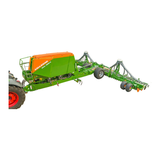
(Fig. 27/7) with the adjustable drag tines can be used. The implement can be folded to a transport width of 3 m and trans- ported on the running gear (Fig. 27/8). Citan 12001-C/15001-C BAH0094-3 12.2019... -
Page 52: Hydraulic Hose Lines
Stickers are applied on the implement for the markings that illustrate the respective hydraulic functions. Fig. 28 Citan 12001-C/15001-C BAH0094-3 12.2019... -
Page 53: Service Brake System
The crank (Fig. 30/1) is used to activate the parking brake. Engaging the parking brake: Turn the crank to the right Releasing the parking brake: Turn the crank to the left Fig. 30 Citan 12001-C/15001-C BAH0094-3 12.2019... -
Page 54: Dual-Circuit Pneumatic Braking System
Germany and a few other EU countries. The hydraulic service braking system acts on two braking cylinders which actuate the brake shoes in the brake drums. The tractor also has to be equipped with a hydraulic service brake system. Citan 12001-C/15001-C BAH0094-3 12.2019... -
Page 55: Isobus
The implement can be connected to any ISOBUS-compatible control terminal. If the tractor has an ISOBUS system, the AMAZONE job computer can also be connected to the existing ISOBUS socket of the tractor and operated with the on-board terminal. As an option, the combination can be delivered e.g. -
Page 56: On-Board Electrical System (Optional)
The hydraulic drive is switched on together with the fan. Fig. 35 As soon as the charging signal (Fig. 36/2) is turned off, the loading procedure begins and the electric energy is stored in the battery (Fig. 36/1). Fig. 36 Citan 12001-C/15001-C BAH0094-3 12.2019... -
Page 57: Frame And Implement Sections
that is nearly vertical before the implement sections are folded in. two implement sections that can be folded for transport (Fig. 37/5) Support wheels for the implement sections (Fig. 37/6). Citan 12001-C/15001-C BAH0094-3 12.2019... -
Page 58: Control Centre
Stowage compartment The storage compartment (Fig. 40/1) contains the accessories kit with the operating man- ual, the metering rollers in parking position, the scale for the calibration test the control terminal Fig. 40 Citan 12001-C/15001-C BAH0094-3 12.2019... -
Page 59: Reservoir
When the fan is running, the hopper cover (Fig. 42/1) must be firmly closed (see section "Filling the hopper", page 184). Fig. 41 Fig. 42 Each hopper chamber is marked with a number (Fig. 43/1) on the metering unit. Fig. 43 Citan 12001-C/15001-C BAH0094-3 12.2019... -
Page 60: Filling Auger
The filling auger (Fig. 46/2), driven by a hydraulic motor, fills the hopper (Fig. 46/1). The filling auger is hydraulically swivelled from transport to working position and vice-versa. The tractor engine must be running when swivelling and when filling the hopper. Fig. 46 Citan 12001-C/15001-C BAH0094-3 12.2019... -
Page 61: Digital Fill Level Monitoring
(Fig. 48). Other sources are also possible (refer to the "ISOBUS software" operating manual). The working speed data is used to determine: the worked area (hectare counter) the required speed for the speed of the metering roller(s). Fig. 48 Citan 12001-C/15001-C BAH0094-3 12.2019... -
Page 62: Hand Wash Tank
The materials used to construct the Fig. 50 hand wash tank are not food-safe 5.10 Soap dispenser Easily accessible, the soap dispenser is on the hose cabinet (Fig. 51/1). Fig. 51 Citan 12001-C/15001-C BAH0094-3 12.2019... -
Page 63: Work Lights (Optional)
(1) 2x 24 W LED on the distributor heads In addition to the LED floodlights on the hopper; however, only when supplied and operated via ISOBUS. Fig. 53 Fig. 54/... (1) Metering unit lighting Fig. 54 Citan 12001-C/15001-C BAH0094-3 12.2019... - Page 64 The hopper interior lighting along with the view- ing window (Fig. 55/2) allow quick checking of the fill level. If light can be seen through the viewing window, the fill level is lower than the viewing window. Without illustration: Ascent lighting Fig. 55 Citan 12001-C/15001-C BAH0094-3 12.2019...
-
Page 65: Quick Emptying (Optional)
5. Clean the sealing area of the quick emptying before putting back into operation. 6. Close the quick emptying. Fig. 56 7. Secure the lever (Fig. 56/1) using the knurled screw (Fig. 56/2). Fig. 57 Citan 12001-C/15001-C BAH0094-3 12.2019... -
Page 66: Seed / Fertiliser Metering
(see "ISOBUS software" operating manual) or with the gearbox lever (Fig. 61/1) of the Vario gearbox. Fig. 60 The higher the number the gearbox lever points to on the scale (Fig. 61/2), the greater the appli- cation rate. Fig. 61 Citan 12001-C/15001-C BAH0094-3 12.2019... - Page 67 When not in use, the calibration troughs are in- serted inside one another and secured in the transport bracket using a linch pin (Fig. 65/4). Citan 12001-C (Fig. 64/3) Citan 15001-C (Fig. 65/3) Fig. 64 The calibration crank is inserted in the transport bracket in parking position.
-
Page 68: Metering Rollers
, 210 cm 600 cm can be diminished by installing idler wheels (Fig. 68/2) to reduce the metered quanti- Fig. 68/… (1) Metering wheels (2) Idler wheels Conversion as shown in section 5.14.1, page 70. Fig. 68 Citan 12001-C/15001-C BAH0094-3 12.2019... - Page 69 Structure and function Fit all of the seed metering units with the same metering roller. Fit the fertiliser metering unit with the fertiliser metering roller. 7.5 cm 20 cm 40 cm 120 cm 210 cm 350 cm Citan 12001-C/15001-C BAH0094-3 12.2019...
-
Page 70: Converting The Metering Roller
(2) Rearrange the metering wheels or replace by idler wheels. Ensure that the arrangement is symmetrical! (3) Position the metering wheels on the drive shaft, put on the locking ring Fig. 70 Citan 12001-C/15001-C BAH0094-3 12.2019... -
Page 71: Metering Rollers Table
Beans Buckwheat Spelt Fertiliser (granular) Peas Flax (dressed) Barley Grass seeds Oats Millet Caraway Lupines Lucerne Maize Poppy Oilseed (moist dressed) Fodder radish Phacelia Rapeseed Rice Red clover White mustard Sunflowers Turnips Triticale Wheat Vetches Citan 12001-C/15001-C BAH0094-3 12.2019... -
Page 72: Calibration Test
30 kg/ha An inner white scale (Fig. 72/2) for all spread rates below 30 kg/ha A coloured scale (Fig. 72/3) with all gearbox settings from 1 to 100. Fig. 72 Citan 12001-C/15001-C BAH0094-3 12.2019... -
Page 73: Fan
The fan speed is set correctly when the indicator for the pressure gauge is between 45 and 60 mbar. At an idle, pressures between 25 and 35 bar are reached in the individual hopper chambers. Fig. 75 Citan 12001-C/15001-C BAH0094-3 12.2019... -
Page 74: On-Board Hydraulic System (Optional)
The PTO shaft hydraulic pump (Fig. 76/1) is driven by the tractor PTO shaft. Fig. 76 In a closed circuit, the implement carries the hydraulic fluid in an oil tank. Fig. 77/… (1) PTO shaft hydraulic pump in parking posi- tion Fig. 77 Citan 12001-C/15001-C BAH0094-3 12.2019... -
Page 75: Distributor Head
The seed line monitoring is not trig- gered. There is no warning message. The warning message is only triggered if the if the seed line is blocked between the sensor and the air separator. Citan 12001-C/15001-C BAH0094-3 12.2019... -
Page 76: Rotec Pro Coulter
RoTeC pro S coulter The RoTeC pro-S coulter is being developed and its function is comparable to the RoTeC pro coulter. Thanks to a modified furrow former, the RoTeC pro-S coulter can achieve a greater seed placement depth. Citan 12001-C/15001-C BAH0094-3 12.2019... -
Page 77: Seed Placement Depth
Fig. 82 gripping the soil. The "Control 25" depth limiting roller (Fig. 83) permits shallow seeding, even on very light soils, thanks to the wider tread surface. Fig. 83 Citan 12001-C/15001-C BAH0094-3 12.2019... -
Page 78: Coulter Pressure
If the pressure gauge is depressurised: The coulters work with normal coulter pressure. If the pressure gauge is pressurised: The coulters work with increased coulter pres- sure. Set the required coulter pressure with the blue Fig. 85 tractor control unit. Citan 12001-C/15001-C BAH0094-3 12.2019... -
Page 79: Exact Following Harrow
The lever rests upon a pin in the adjuster segment. The higher the pin is inserted in the group of holes, the greater the harrow pressure (see sec- tion 8.8, page 149). Fig. 87 Citan 12001-C/15001-C BAH0094-3 12.2019... -
Page 80: Hydraulic Exact Following Harrow Pressure Adjustment (Optional)
Voids are closed and obstruct snails' access to the seed. The following are adjustable the working depth of the harrow tines Fig. 89 the angle of the harrow tines the roller pressure Citan 12001-C/15001-C BAH0094-3 12.2019... -
Page 81: Guide Wheel Harrow
When lifting the implement at the headlands or for road transport, the wheel mark eradicators are swivelled up by approx. 90°. Fig. 91 Throwing the lever (Fig. 92/A) allows work to be performed without the tractor wheel mark eradicators. Fig. 92 Citan 12001-C/15001-C BAH0094-3 12.2019... -
Page 82: Seed Drill Wheel Mark Eradicator (Optional)
Wheel mark eradicator (Fig. 93/1) for eliminating the seed drill wheel tracks. Fig. 93 5.26 Track marker (optional, only for Citan 12001-C) The hydraulically-actuated track markers dig into the ground alternately on the left and the right of the implement. In doing so, the active track marker creates a mark. -
Page 83: One-Sided Switching Off (Part-Width Section)
Fig. 96 If all coulters are working one metering unit (Fig. 97/1) supplies both distributor heads with seed or fertiliser at the same time. Fig. 97 Citan 12001-C/15001-C BAH0094-3 12.2019... -
Page 84: Creating Tramlines (Option)
(Fig. 99/1), which open the and close the seed line tubes (Fig. 99/2), are working properly. An acoustic warning signal is issued if the posi- tion is faulty. The seed supply to the tramline coulters are marked with coloured labels (Fig. 100/1). Fig. 100 Citan 12001-C/15001-C BAH0094-3 12.2019... - Page 85 Seed drill working width 12.0 m 15.0 m Tramline spacing Tramline rhythm (working width of the fertiliser spreader and field sprayer) 24 m 30 m 48 m 36 m 45 m 30 m 18 m 42 m Fig. 102 Citan 12001-C/15001-C BAH0094-3 12.2019...
-
Page 86: Tramline Rhythm No. 1
Tramline distance 24 m Tramline counter display (D) Working width of the seed drill (A) 15 m Working width of the fertiliser spreader/field 30 m sprayer (B) Tramline distance 30 m Fig. 104 Tramline counter display (D) Citan 12001-C/15001-C BAH0094-3 12.2019... -
Page 87: Tramline Rhythm No. 2
36 m 2/0/1 Tramline counter display (D) Working width of the seed drill (A) 15 m Working width of the fertiliser spreader/field 45 m sprayer (B) Tramline distance 45 m Fig. 106 2/0/1 Tramline counter display (D) Citan 12001-C/15001-C BAH0094-3 12.2019... -
Page 88: Tramline Rhythm No. 37
Working width of the seed drill (A) 12 m Working width of the fertiliser spreader/field 30 m sprayer (B) Tramline distance 30 m Tramline counter display, left (D) 1/2/3/0/5/6/0/8/9/10 Tramline counter display, right 1/0/3/4/5/6/7/8/0/10 Fig. 108 Citan 12001-C/15001-C BAH0094-3 12.2019... -
Page 89: Tramline Rhythm No. 43
Working width of the seed drill (A) 12 m Working width of the fertiliser spreader/field 42 m sprayer (B) Tramline distance 42 m 1/0/3/4/5/6/7/8/9/10/11/12/0/13 Tramline counter display, left (D) Tramline counter display, right 1/2/3/4/5/0/7/8/0/10/11/12/13/14 Fig. 109 Citan 12001-C/15001-C BAH0094-3 12.2019... -
Page 90: Initial Operation
This does not apply to equipment movements that: are continuous or are automatically locked or require a float position or pressure position due to their function. Citan 12001-C/15001-C BAH0094-3 12.2019... -
Page 91: Checking The Suitability Of The Tractor
The front axle of the tractor must always be subjected to at least 20 % of the tare weight of the tractor. The tractor must achieve the brake delay specified by the tractor manufacturer, even with the implement connected. Citan 12001-C/15001-C BAH0094-3 12.2019... -
Page 92: Calculating The Actual Values For The Total Tractor Weight, Tractor Axle Loads And Load Capacities, As Well As The Minimum Ballast
§ 70 of the German Regulations Authorising the Use of Vehicles for Road Traffic and the required approval according to § 29, paragraph 3 of the Ger- man Road Traffic Regulations. Citan 12001-C/15001-C BAH0094-3 12.2019... -
Page 93: Data Required For The Calculation (Hitched Implement)
See tractor operating manual or vehicle documents or measurement [m] Distance between the centre of the rear See tractor operating manual or vehicle axle and the centre of the lower link con- documents or measurement nection Citan 12001-C/15001-C BAH0094-3 12.2019... -
Page 94: Calculation Of The Required Minimum Ballasting At The Front G
(section 6.1.1.7). 6.1.1.6 Tyre load capacity Enter the double value (two tyres) of the approved load capacity (see, for example, tyre manufacturer's documentation) in the table (section 6.1.1.7). Citan 12001-C/15001-C BAH0094-3 12.2019... -
Page 95: Table
(if required) attached to the tractor for the minimum front ballast (G V min You must use a front weight, which is equal to at least the required minimum front ballast (G V min Citan 12001-C/15001-C BAH0094-3 12.2019... -
Page 96: Requirements For Tractor Operation With Towed Implements
that the permissible total weight of the tractor is complied with that the approved load capacities of the tractor tyres are not exceeded. Citan 12001-C/15001-C BAH0094-3 12.2019... -
Page 97: Securing The Tractor/Implement Against Unintentional Start-Up And Rolling
This is how to prevent unintentional lowering. 3. Shut down the tractor engine. 4. Remove the ignition key. 5. Apply the tractor parking brake. 6. Secure the implement with wheel chocks against unintentionally rolling away. Citan 12001-C/15001-C BAH0094-3 12.2019... -
Page 98: Installation Regulations For The Hydraulic Blower Fan Drive Connection
The capacity of the tractor's oil tank (Fig. 111/4) should be at least twice the oil flow rate. If the hydraulic fluid heats up excessively, the installation of an oil cooler is required at a specialist workshop. Citan 12001-C/15001-C BAH0094-3 12.2019... -
Page 99: Installing The Wheels
If the implement is equipped with emergency wheels, the running wheels must be installed before initial operation. Workshop work WARNING The rims for the tyres must have a rim disc that has been fully welded all the way around! Citan 12001-C/15001-C BAH0094-3 12.2019... - Page 100 Required tightening torque for wheel nuts: 510 Nm. 4. Put the running wheels onto the stud bolts. 5. Tighten the wheel nuts. 6. Lower the implement and remove the slings. 7. Retighten the wheel nuts after 10 operating hours. Citan 12001-C/15001-C BAH0094-3 12.2019...
-
Page 101: Coupling And Uncoupling The Implement
5. Install the guard plate. 6. Put on the nut and tighten at 450 Nm. 7. Repeat the procedure for the second lower link pin. 8. Retighten the nuts after 10 operating hours. Fig. 112 Citan 12001-C/15001-C BAH0094-3 12.2019... -
Page 102: Coupling The Implement
If the tractor has been separated from the implement, always secure the implement with the service parking brake and also with 2 wheel chocks. secure the implement with 2 wheel chocks if it has no brake system! Citan 12001-C/15001-C BAH0094-3 12.2019... - Page 103 CAUTION Danger of getting crushed in the area of the moving tensioned crosspiece. 1. Verify that the implement is secured with wheel chocks (Fig. 113/1). Fig. 113 Citan 12001-C/15001-C BAH0094-3 12.2019...
- Page 104 11. Apply the tractor parking brake, switch the Fig. 116 tractor engine off and remove the ignition key. 12. Connect the supply lines to the tractor (see section 7.3 to 7.6, starting on page 106). Citan 12001-C/15001-C BAH0094-3 12.2019...
- Page 105 17. Check the function of the braking and lighting system. 18. Stow the wheel chocks (Fig. 119/1) in the brackets and secure with a wing nut (Fig. 119/2). 19. Before commencing a run, perform a braking test. Fig. 118 Fig. 119 Citan 12001-C/15001-C BAH0094-3 12.2019...
-
Page 106: Connecting The Hydraulic Connections
The tractor control unit must be used in different types of activa- tion, depending on the hydraulic function. Latched, for a permanent oil circulation Tentative, activate until the action is executed Float position, free oil flow in the control unit Citan 12001-C/15001-C BAH0094-3 12.2019... - Page 107 Coulter pressure acting Reduce switch on Single- Hydraulic motor blower fan double- acting Return flow: unpressurised line Pressure line with priority Unpressurised line (see section "Installation regulations for the hydraulic blower fan drive connection", page Citan 12001-C/15001-C BAH0094-3 12.2019...
-
Page 108: Coupling The Hydraulic Hose Lines
(neutral position). 2. Clean the hydraulic connectors of the hydraulic hose lines before you couple the hydraulic hose lines to the tractor. 3. Connect the hydraulic hose line(s) to the tractor control unit(s). Fig. 120 Citan 12001-C/15001-C BAH0094-3 12.2019... -
Page 109: On-Board Hydraulic System
Stellen Sie sicher, dass die Verk nüpfung auf die k orrek te Datei und den Boom k orrek ten Sp eicherort zeig t. acting Move into working position Fan hydraulic switch on Single motor Citan 12001-C/15001-C BAH0094-3 12.2019... -
Page 110: Uncoupling The Hydraulic Hose Lines
2. Release the hydraulic connectors from the hydraulic sockets. 3. Place the hydraulic hose lines in the hose cabinet. Depending on the implement equipment: Hose cabinet (Fig. 122/1) Hose cabinet (Fig. 123/1) Fig. 122 Fig. 123 Citan 12001-C/15001-C BAH0094-3 12.2019... -
Page 111: Making Further Connections
(red) is connected. Only then can the wheel chocks be removed. Compliance with the maintenance intervals is essential for the correct function of the brake system. Citan 12001-C/15001-C BAH0094-3 12.2019... - Page 112 The brake is not released if the implement's parking brake is applied. To make sure that the implement is braked after uncoupling, apply the implement's parking brake beforehand. Only release the parking brake once the implement has been coupled up to the tractor. Citan 12001-C/15001-C BAH0094-3 12.2019...
-
Page 113: Coupling The Brake And Supply Lines
Check the routing of the brake line. The brake line must not chafe on other parts. On the tractor, couple the yellow coupling head first (brake line). and then the red coupling head (supply line). Citan 12001-C/15001-C BAH0094-3 12.2019... - Page 114 The black button is pushed out when the supply line (red) is coupled. If the tractor parking brake is: engaged, the service brake of the im- plement is also engaged. released, the service brake of the im- plement is also released. Citan 12001-C/15001-C BAH0094-3 12.2019...
-
Page 115: Uncoupling The Supply And Brake Line
First secure the implement with the wheel chocks (Fig. 126) before you uncouple the implement from the tractor! Fig. 126 Fig. 127/… (1) Wheel chock (parking position on the main frame in front of the running gear tyres) Fig. 127 Citan 12001-C/15001-C BAH0094-3 12.2019... - Page 116 3. Release the coupling head (Fig. 129) of the supply line (red). 4. Release the coupling head of the brake line (yellow). 5. Fasten the coupling heads in the empty couplings. 6. Close the covers of the coupling heads on the tractor. Fig. 129 Citan 12001-C/15001-C BAH0094-3 12.2019...
-
Page 117: Control Elements Of The Dual-Circuit Pneumatic Braking System
Fig. 130 With a full compressed air tank, the brakes are released immediately when the supply line (red) is connected to the tractor. The button (Fig. 130/1) can then no longer be moved. Citan 12001-C/15001-C BAH0094-3 12.2019... -
Page 118: Connecting The Hydraulic Brake System
10 seconds with the engine running. This fills the hydraulic accumulator. When the hydraulic accumulator is full, the implement's service brake system responds when the tractor brake pedal or the tractor parking brake is applied. Citan 12001-C/15001-C BAH0094-3 12.2019... - Page 119 If the implement is separated from the tractor due to an accident, the implement will be braked. Fig. 133 7. The position of the break-away valve provides information about the position of the brake shoes. Fig. 134 Citan 12001-C/15001-C BAH0094-3 12.2019...
-
Page 120: Uncoupling The Hydraulic Service Brake System
5. Push the hydraulic socket onto the protective cap (Fig. 137/1). The protective cap is secured to the hose cabinet and protects the socket against soiling in the parking position. Fig. 137 Citan 12001-C/15001-C BAH0094-3 12.2019... -
Page 121: Uncoupling The Implement
4. Apply the tractor parking brake, switch the tractor engine off and remove the ignition key. Fig. 138 5. Unlock the pin. 5.1 Turn the locked pin (Fig. 139/1) by ° until the clamping sleeve (see Fig. 141/1) is released. Fig. 139 Citan 12001-C/15001-C BAH0094-3 12.2019... - Page 122 Fig. 142 10. Secure the implement wheels with two wheel chocks (Fig. 143/1) 11. Uncouple the supply line and the brake line from the tractor (see section "Uncoupling the supply and brake line", page 115) Fig. 143 Citan 12001-C/15001-C BAH0094-3 12.2019...
- Page 123 (see tractor operating manual). 18. Uncouple the tractor's lower link. 19. Pull the tractor forwards. DANGER While pulling the tractor forwards no personnel are allowed to be between the tractor and the im- plement! Citan 12001-C/15001-C BAH0094-3 12.2019...
-
Page 124: Safety Device Against Unauthorised Use
Coupling and uncoupling the implement Safety device against unauthorised use Lockable device for the drawbar eye, ball brack- et, or lower link crosspiece, prevents unauthor- ised use of the machine. Fig. 145 Citan 12001-C/15001-C BAH0094-3 12.2019... -
Page 125: Settings
(see section 10.1, page 173) Switch off the tractor's PTO shaft. Wait until the tractor's PTO shaft stops moving. Apply the tractor's parking brake Switch off the tractor's engine Remove the ignition key. Citan 12001-C/15001-C BAH0094-3 12.2019... -
Page 126: Repositioning The Fill Level Sensor
This ensures that the sensor head (Fig. 148/2) protrudes into the seed or fertiliser. 5. Tighten up the nut (Fig. 146/1). The close the opening, insert the dummy (Fig. 146/3) into the holder and clamp it firmly. Fig. 148 Citan 12001-C/15001-C BAH0094-3 12.2019... -
Page 127: Installing/Removing The Metering Roller
2.2 Release two nuts (Fig. 150/1) but do not remove. Fig. 149 Fig. 150 3. Swivel the bolts (Fig. 151/1). 4. Push the shutter (Fig. 151/2) into the dosing unit up to the stop. Fig. 151 Citan 12001-C/15001-C BAH0094-3 12.2019... - Page 128 Fig. 153 7. Pull the metering roller out of the metering unit. Install the metering roller in the re- verse sequence. Fig. 154 Set the shutter to the parking position and secure with two bolts (seeFig. 150). Citan 12001-C/15001-C BAH0094-3 12.2019...
-
Page 129: Calibrating The Spread Rate
5. Release the tensioning hooks and open the folding of the left conveyor section (Fig. 155/2). 6. Depending on the implement equipment, follow section 8.3.2 (see page 130) or sec- tion 8.3.3 (see page 135). Citan 12001-C/15001-C BAH0094-3 12.2019... -
Page 130: Mechanical Drive
Litre weight [kg/L] Conversion factors: Gearbox position 20 0.088 rpm Gearbox position 80 0.351 rpm Körner Conversion Tausendkor ngwicht Grains per m² to Saatstärke kg/ha Keimfähigk Citan 12001-C/15001-C BAH0094-3 12.2019... -
Page 131: Example For The Calculation Of Metering Volumes For Wheat
8.3.2.2 Example for the calculation of metering volumes for wheat 175 kg/ha of wheat with a litre weight of 0.85 kg/l are to be metered with a Citan 12001-C. Specification: Litre weight 0.85 kg/L Working width per metering unit... -
Page 132: Determining The Gearbox Setting Using The Calculating Disc Rule
The correct gearbox setting can be determined using the calculator disc with the values from the first calibration test and the calculated application rate (see section "Determining the gear- box setting using the calculating disc rule", page 132). Citan 12001-C/15001-C BAH0094-3 12.2019... -
Page 133: Calibration Procedure
10. Empty the calibration trough and push it back under the metering unit. Fig. 160 Citan 12001-C/15001-C BAH0094-3 12.2019... - Page 134 14. Repeat the calibration test until the desired application rate is achieved. 15. Secure the calibration trough on the transport bracket. 16. Close the openings under each metering unit. 17. Clip the calibration crank into its transport bracket. Citan 12001-C/15001-C BAH0094-3 12.2019...
-
Page 135: Electric Drive
Set the scale to the desired units (kg or lb). Fig. 164 6. Repeat the calibration test until the desired application rate is achieved. 7. Secure the calibration trough on the transport bracket. 8. Close the openings under each metering unit. Citan 12001-C/15001-C BAH0094-3 12.2019... -
Page 136: Adjusting Fan Speed
5 mbar! If the system pressure is not reached, check the system for leaks. Fig. 165 At an idle, pressures between 25 and 35 bar are reached in the individual hopper chambers. Citan 12001-C/15001-C BAH0094-3 12.2019... -
Page 137: Blower Fan Speed In Multiple Chamber Systems
Set the target blower fan speed via the tractor's flow control valve or (if not present) via the pressure relief valve of the blower fan hydraulic motor if the tractor does not have a flow control valve. Citan 12001-C/15001-C BAH0094-3 12.2019... - Page 138 Required system pressure: 45 - 60 mbar The pressure difference between the indi- vidual hopper chambers may not exceed a maximum of 5 mbar! 4. If the system pressure is not reached, check the system for leaks. Fig. 167 Citan 12001-C/15001-C BAH0094-3 12.2019...
-
Page 139: Setting The Blower Fan Speed Via The Flow Control Valve Of The Tractor
( Fig. 168/1) See section 8.4.3.1. „Pressure relief valve with round outer contour“ Fig. 168 2.2 Pressure relief valve with hexagonal outer contour ( Fig. 169/1) See section 8.4.3.2. „Pressure relief valve with hexagonal outer contour“ Fig. 169 Citan 12001-C/15001-C BAH0094-3 12.2019... -
Page 140: Pressure Relief Valve With Round Outer Contour
4000 rpm. Fig. 171 Blower fan speed Turn to the right: Increase the nominal blower fan speed Turn to the left: Reduce the nominal blower fan speed 3. Tighten the lock nut. Citan 12001-C/15001-C BAH0094-3 12.2019... -
Page 141: Pressure Relief Valve With Hexagonal Outer Contour
4000 rpm. Fig. 173 Blower fan speed Turn to the right: Increase the nominal blower fan speed Turn to the left: Reduce the nominal blower fan speed 3. Tighten the lock nut. Citan 12001-C/15001-C BAH0094-3 12.2019... - Page 142 PTO shaft speed. Do not exceed the following speeds: max. 1000 rpm PTO shaft speed, max. 4000 rpm blower fan speed. The blower fan speed is displayed on the control terminal. Fig. 174 Citan 12001-C/15001-C BAH0094-3 12.2019...
-
Page 143: Setting The Sections Pressure
(1) Pressure relief valve under the operation platform (2) Adjustment screw for the sections pressure (3) Pressure gauge, shows the set sections pressure. Fig. 176 The sections pressure setting depends on the Soil texture Coulter pressure Forward speed Citan 12001-C/15001-C BAH0094-3 12.2019... - Page 144 3.2 Support wheels of the booms are exposed to high loads: Reduce the pressure on the booms by 5 bar. 4. The pressure gauge (Fig. 177/1) shows the set section pressure. 5. Tighten the lock nut. Citan 12001-C/15001-C BAH0094-3 12.2019...
-
Page 145: Adjusting The Seed Placement Depth
1. Allow the handle (Fig. 178/1) to engage in the desired position. The specified values (see section 8.6.1) are to be considered as reference values! Fig. 178 Citan 12001-C/15001-C BAH0094-3 12.2019... -
Page 146: Positioning The Depth Limiting Discs
Fig. 179 Without depth > 4 – 6 > 5 – 7 limiting disc *) Because of the modified furrow former geometry, the RoTeC pro-S coulter reaches greater place- ment depths than the RoTeC pro coulter. Citan 12001-C/15001-C BAH0094-3 12.2019... -
Page 147: Seeding Without Plastic Disc
The shoulder must grip in the slot. 2. Pull the handle to the rear and upwards beyond the notches. A light knock on the centre of the disc helps to latch it into position. Citan 12001-C/15001-C BAH0094-3 12.2019... -
Page 148: Setting The Coulter Pressure
The pressure gauge is unpressurised: The coulters are working with normal coul- ter pressure (Fig. 181/1). Pressure is applied to the pressure gauge: The coulters are working with increased coulter pressure (Fig. 181/2). Fig. 183 Citan 12001-C/15001-C BAH0094-3 12.2019... -
Page 149: Adjusting The Exact Following Harrow
3. Remove the linch pin (Fig. 185/1) Fig. 185 4. Move the adjustable spindle to the desired position (Fig. 185/2) and secure with a linch pin 5. Carry out the same settings (Fig. 186/3) on all adjuster segments. Fig. 186 Citan 12001-C/15001-C BAH0094-3 12.2019... -
Page 150: Setting The Exact Following Harrow Pressure
(Fig. 189/4) and se- cure (Fig. 189/5) 6. The higher the pin is inserted in the adjustment scale (Fig. 189/1+), the greater the exact following harrow pressure. 7. Apply the same setting to all adjuster segments. Fig. 189 Citan 12001-C/15001-C BAH0094-3 12.2019... -
Page 151: Setting The Exact Following Harrow Pressure (Hydraulic Adjustment)
Roller harrow DANGER Carry out the adjustments only with the tractor PTO shaft shaft shut off, the tractor parking brake applied, the engine shut off and the ignition key removed! Check the work results after each adjustment. Citan 12001-C/15001-C BAH0094-3 12.2019... -
Page 152: Setting Working Depth And Pitch Of Harrow Tines
(Fig. 192/3) in the adjuster segment. The lower the pin (Fig. 192/2) is inserted in the adjuster segment, the flatter the pitch. 7. After each repositioning, secure the pin (Fig. 192/2) with a spring cotter pin. Citan 12001-C/15001-C BAH0094-3 12.2019... -
Page 153: Adjusting The Roller Pressure
Roller contact Roller diameter pressure D [mm] F [kg] 330 mm max. 35 kg The roller contact pressure "F" must not exceed the table value. Higher pressures than indicated may damage the roller harrow. Fig. 195 Citan 12001-C/15001-C BAH0094-3 12.2019... -
Page 154: Adjusting The Seed Drill Wheel Mark Eradicator
Increase working depth: Reduce working depth: 1. Loosen the nuts (Fig. 198/1) and remove them. 2. Move the harrow arm (Fig. 198/2) to the desired position. 3. Put on the nuts and tighten them. Fig. 198 Citan 12001-C/15001-C BAH0094-3 12.2019... -
Page 155: Adjusting The Pitch Of The Guide Wheel Harrow
5. Put on the nut and tighten it. Fig. 199 8.11.3 Adjusting the working position of the guide wheel harrow 1. Loosen the nut (Fig. 200/1). 2. Move the harrow arm (Fig. 200/2) to the desired position. 3. Tighten the nut. Fig. 200 Citan 12001-C/15001-C BAH0094-3 12.2019... -
Page 156: Adjusting The Tractor Wheel Mark Eradicator (Optional)
Valve lever position A: Transport position Valve lever position B: Working position Putting the valve lever into position A prevents accidental swivelling of the tractor wheel mark eradicators from transport position into working position. Fig. 203 Citan 12001-C/15001-C BAH0094-3 12.2019... -
Page 157: Adjusting The Support Wheel Height
2. Loosen the lower nuts, remove the bolts (Fig. 204/1) 3. Swivel the support wheel arm to the desired position Fig. 204 Position of the bolt Height [mm] (Fig. 204/1) (Fig. 204/3) - 50 - 25 Centre position + 25 Citan 12001-C/15001-C BAH0094-3 12.2019... -
Page 158: Adjusting The Track Marker (Optional, Only For Citan 12001-C)
(Fig. 204/1) and tighten with nuts 5. Tighten the upper nuts (Fig. 204/2) 8.14 Adjusting the track marker (optional, only for Citan 12001-C) DANGER It is forbidden to stand in the swivelling area of the track marker! 1. Direct people out of the danger area. -
Page 159: Setting The Tramline Rhythm/Counter (Optional)
The tramline counter is coupled with the working position sensor on the star wheel. Each time the implement or the star wheel is lifted, the tramline counter advances by one digit. Pressing the STOP button before lifting the star wheel prevents the tramline counter from advancing. Citan 12001-C/15001-C BAH0094-3 12.2019... -
Page 160: Adjusting The Tramline To The Track Width/Wheelmark Width (Specialist Workshop)
Deactivate any shutters (Fig. 209/2) that are not needed (see page 161). Deactivated shutters do not close the feed lines to the tramline coulters. Always activate or deactivate pairs of shutters positioned opposite each other on the base plate. Citan 12001-C/15001-C BAH0094-3 12.2019... -
Page 161: Activating / Deactivating Shutters
12. The shutter (Fig. 212/3) is inserted in the guide. Deactivating the shutters: 13. Turn the shutters around (Fig. 212/3) and push them into the drill hole (Fig. 212/4). 14. Screw the shutter tunnel (Fig. 212/2) onto the base plate. Fig. 212 Citan 12001-C/15001-C BAH0094-3 12.2019... -
Page 162: Half-Sided Switching Off
3. Throw the lever to the right (Fig. 214/1) and lock it: the right side of the implement is switched off. requires the halving of the application rate. Fig. 214 Citan 12001-C/15001-C BAH0094-3 12.2019... - Page 163 (Fig. 216/1) accord- ingly. Fig. 216 Optionally, a setting motor ( Fig. 217/1) actuates the electronic one-sided switching. If the one-sided switching is actuated electrically, the application rate is set automatically. Fig. 217 Citan 12001-C/15001-C BAH0094-3 12.2019...
-
Page 164: Adjusting The Tramline Marker
1. Set the track marker more or less on grip. 2. Loosen the nut (Fig. 219/1) and rotate the track marker disc together with the wedges (Fig. 219/2). 3. Tighten the nut. 4. Repeat the procedure for the second track marker disc Fig. 219 Citan 12001-C/15001-C BAH0094-3 12.2019... -
Page 165: Transportation
Risks of being crushed, cut, caught, drawn in or struck if the implement is unintentionally released from its attached or hitched position. Before transportation, visually check that the lower links are properly secured against accidental loosening. Citan 12001-C/15001-C BAH0094-3 12.2019... - Page 166 Instruct people to leave the loading site before approaching the implement. DANGER Lock the tractor control units during road transport! DANGER In bends take into consideration the wide sweep and the centrif- ugal mass of the implement. Citan 12001-C/15001-C BAH0094-3 12.2019...
-
Page 167: Set The Implement To Road Transport Mode
(see section "Transportation equipment (optional)", page 42). 9. Switch the work lights off during transport to avoid blinding other motorists. DANGER Lock the tractor control units during road transport! Citan 12001-C/15001-C BAH0094-3 12.2019... - Page 168 1. Take the road safety bars (Fig. 221/2) out of the storage compartment. 2. Install the road safety bars (Fig. 221/2). Hook the tension cables (Fig. 221/3) onto the harrow tines (Fig. 221/1). Fig. 221 Citan 12001-C/15001-C BAH0094-3 12.2019...
-
Page 169: Legal Regulations And Safety
Revolving beacon In several countries, the implement and/or the tractor must be equipped with a revolving beacon. Ask your local importer/implement dealer about the legal guidelines. The revolving beacon is subject to approval in Germany. Citan 12001-C/15001-C BAH0094-3 12.2019... - Page 170 These risks pose serious injuries or death. Comply with the maximum load of the mounted / towed implement and the approved axle and drawbar loads of the tractor. Citan 12001-C/15001-C BAH0094-3 12.2019...
- Page 171 Moreover, the permissible transport width of 3 m is exceeded. Push the outer harrow elements into the main tube of the exact following harrow before you perform any transport journeys. In bends take into consideration the wide sweep and the centrifugal mass of the implement. Citan 12001-C/15001-C BAH0094-3 12.2019...
-
Page 172: Use Of The Implement
Risk of contusions, drawing in and catching during implement operation without the intended protective equipment! Only ever start up the implement when the protective equipment is fully installed. Only actuate the tractor control units from inside the tractor cab! Citan 12001-C/15001-C BAH0094-3 12.2019... -
Page 173: Unfolding/Folding The Implement Booms
1. In combination with track markers, set the valve lever (Fig. 222/1) to position "A". The valve switches to unfold the implement booms. Fig. 222 2. Lift the implement sections out of the transport socket (Fig. 223/1). Fig. 223 Citan 12001-C/15001-C BAH0094-3 12.2019... - Page 174 Fig. 226 8. Set the valve lever (Fig. 227/1) to position "B" and leave it in position "B" during opera- tion. The valve switches to actuate the track markers. Fig. 227 Citan 12001-C/15001-C BAH0094-3 12.2019...
-
Page 175: Folding The Implement Sections
Keep actuating the green 2 control unit until the distributor heads are folded (see Fig. 230) the implement sections (Fig. 231/1) are resting on the skids (Fig. 231/2) of the lock hooks. Fig. 230 Citan 12001-C/15001-C BAH0094-3 12.2019... - Page 176 7. Move the implement into a horizontal position by actuating the tractor lower links. The implement requires sufficient ground clearance in all driving situa- tions. 8. Set the valve lever in the down position. 9. Switch off the control terminal. Fig. 233 Citan 12001-C/15001-C BAH0094-3 12.2019...
-
Page 177: Folding / Unfolding The Track Marker (Only Citan 12001-C)
Use of the implement 10.2 Folding / unfolding the track marker (only Citan 12001-C) The track markers can be put in three positions: Working position Parking position Transport position The valve lever (Fig. 234/2) is used to pre-set the desired track marker changing (Fig. -
Page 178: Folding The Track Markers During Operation
2 (Fig. 236/2). 2. Actuate the green 2 tractor control unit. The active track marker is folded from work- ing to transport position. The parked track marker is folded from parking to transport position. Citan 12001-C/15001-C BAH0094-3 12.2019... -
Page 179: Folding/Unfolding The Tractor Wheel Mark Eradicators
Fig. 238 the tractor wheel mark eradicator (option- al)", page 156). WARNING Before road transport, move the valve lever to position A (seeFig. 203, page 156) to prevent accidental swivelling of the tractor wheel mark eradicators. Citan 12001-C/15001-C BAH0094-3 12.2019... -
Page 180: Folding / Unfolding The Tramline Marker
2. Pull out the pin (Fig. 239/1) and fold the section (Fig. 239/2) with the track disc into working position. Fig. 239 3. Secure the connection by inserting the pin (Fig. 240/1) and locking it. 4. Repeat the setting on the second boom. Fig. 240 Citan 12001-C/15001-C BAH0094-3 12.2019... -
Page 181: Move The Tramline Markers To The Transport Position
6. Secure the connection by inserting the pin (Fig. 242/1) and locking it. 7. Repeat the setting on the second boom. Fig. 242 Citan 12001-C/15001-C BAH0094-3 12.2019... -
Page 182: Operating The Filling Auger
5. Swivel the jack (Fig. 246/2) down and lock 6. Swivel the jack (Fig. 246/3) down and lock 7. Using the handle, swivel the filling auger (Fig. 246/4) into working position. 8. Open the funnel tarp (Fig. 246/5). Fig. 246 Citan 12001-C/15001-C BAH0094-3 12.2019... - Page 183 15. Swivel the jack up and lock it (see Fig. Fig. 248 246/3). 16. Swivel the filling auger over the frame and lock it (see Fig. 245/1). 17. Actuate the control unit (see Fig. 244/1) and fold the filling auger into transport position. Citan 12001-C/15001-C BAH0094-3 12.2019...
-
Page 184: Filling The Hopper
Table (Metering Rollers Table, page 71) and install (see section "Installing/removing the metering roller", page 127). 5. Adjust the fill level sensors of the hopper chambers (see section "Repositioning the fill level sensor", page 126). Citan 12001-C/15001-C BAH0094-3 12.2019... - Page 185 2. Pull the ladder down (Fig. 249/2). Fig. 249 3. Push the ladder into working position. Make sure that the ladder reaches the end position. 4. Climb on the loading board via the ladder. Fig. 250 Citan 12001-C/15001-C BAH0094-3 12.2019...
- Page 186 Fig. 251 2. Unlock the lever (Fig. 252/1) Fig. 252 3. Swivel the lever upwards. Ensure that the spring-loaded pin engages (Fig. 253/1). The two handles (Fig. 253/2) are used for opening the hopper cover. Fig. 253 Citan 12001-C/15001-C BAH0094-3 12.2019...
- Page 187 with a filling auger from a supply vehi- from bulk bags. DANGER Never step between the supply vehicle and the implement! Fig. 256 Never stand under suspended loads! Citan 12001-C/15001-C BAH0094-3 12.2019...
- Page 188 The handles (Fig. 253/2) are used to close the hopper cover. Fig. 257 3. Pull out the spring-loaded pin (Fig. 258/1) and swivel the lever (Fig. 258/2) down- wards. Fig. 258 4. Make sure that the spring-loaded pin engages (Fig. 259/1). Fig. 259 Citan 12001-C/15001-C BAH0094-3 12.2019...
- Page 189 In working position, the ladder can be damaged by the drawbar or tractor when turning the implement. 1. Push the ladder up (Fig. 261/1). 2. Ensure that the spring-loaded locking device engages (Fig. 261/2). Fig. 261 Citan 12001-C/15001-C BAH0094-3 12.2019...
-
Page 190: Work Commencement
6. Start. 7. Check the placement depth of the seed and correct if necessary (see section "Checking the seed placement depth", page 191) after 100 m after changing from light to heavy soil and vice-versa. Citan 12001-C/15001-C BAH0094-3 12.2019... -
Page 191: Checking The Seed Placement Depth
(see section "Clean the distributor head", page 203). Visual inspection of the delivery lines The delivery lines may not sag! Accumulations of e.g. fertiliser and seed residues cause increased wear and must be removed immedi- ately. Citan 12001-C/15001-C BAH0094-3 12.2019... -
Page 192: Turning At End Of The Field
During the work, operate the yellow tractor control unit in neutral position. The pressure gauge (Fig. 263/1) indi- cates the pressure that is applied to the hydraulic cylinders. Fig. 263 Citan 12001-C/15001-C BAH0094-3 12.2019... -
Page 193: End Of Work On The Field
seed residues and fertiliser may swell or germinate in the metering units. As a result, rotation of the metering rollers is blocked and damage can be caused to the drive! Citan 12001-C/15001-C BAH0094-3 12.2019... -
Page 194: Emptying The Metering Unit
1. Push a calibration trough (Fig. 266) into the bracket under the metering unit. Fig. 266 2. Close the opening of the hopper above the metering unit with the shutter (Fig. 267/1) (see section "Installing/removing the meter- ing roller", page 127). Fig. 267 Citan 12001-C/15001-C BAH0094-3 12.2019... - Page 195 6. Pull the shutter (Fig. 267/1) slowly out of the metering unit. The seed drops into the calibration trough. 7. Reassembly occurs in the reverse sequence. 8. Secure the calibration trough(s) (Fig. 71) on the transport bracket. Fig. 269 Citan 12001-C/15001-C BAH0094-3 12.2019...
-
Page 196: Faults
Charge the battery with a Battery isolating relay is defective charger Replace the battery isolating relay One-sided switching Resistance when switching Check the folding in the metering unit and actuation rods for ease of movement. Citan 12001-C/15001-C BAH0094-3 12.2019... -
Page 197: Triggering The Track Marker Safety (Citan 12001-C)
Faults 11.2 Triggering the track marker safety (Citan 12001-C) To pass obstacles, the active track marker can be folded and unfolded on the field. If the track marker still encounters a solid obstacle, a shear bolt shears off (Fig. 270/2) and thus protects the track marker from damage. -
Page 198: Residual Quantity Display
Roller bar spring Fig. 274/… (1) Roller bar spring (2) Spring support Only use original parts as a replacement (see the online spare parts list). Tightening (Fig. 274/…) Function torque Spring support 10 Nm Fig. 274 Citan 12001-C/15001-C BAH0094-3 12.2019... -
Page 199: Cleaning, Maintenance And Repairs
(see section 10.1, page 173) The rear frame is fully lowered. The tractor parking brake is applied. The tractor PTO shaft is shut off. The tractor engine is switched off. The ignition key is removed. Citan 12001-C/15001-C BAH0094-3 12.2019... -
Page 200: Securing The Connected Implement
Never treat brake, air and hydraulic hoses with petrol, benzene, petroleum or mineral oils. After cleaning, grease the implement, in particular after cleaning with a high pressure cleaner/steam jet or liposoluble agents. Observe the legal regulations for handing and disposing of cleaning agents. Citan 12001-C/15001-C BAH0094-3 12.2019... - Page 201 Clean the dirty fan guard screen to ensure an unobstructed air flow. If the required quantity of air is not reached, faults may occur in the seed delivery and distribution. Clean the blower fan of any deposits. Deposits lead to imbalance and damage to the bearing. Citan 12001-C/15001-C BAH0094-3 12.2019...
- Page 202 4. Empty the hopper and the metering units (see section "Emptying the hopper and/or metering unit.", page 193). 5. Clean the distributor head (see section "Clean the distributor head", page 203). 6. Clean the implement with water or with a high pressure cleaner. Citan 12001-C/15001-C BAH0094-3 12.2019...
-
Page 203: Clean The Distributor Head
8. Install the plastic cap (Fig. 279/2). 9. Fix the plastic cap with winged nuts (Fig. 279/1). Intensive cleaning requires the shutters to be removed. See section "Adjusting the tramline to the track width/wheelmark width", page 160. Fig. 279 Citan 12001-C/15001-C BAH0094-3 12.2019... -
Page 204: Residual Emptying Of The Filling Auger
After the first heating up, no more grease/oil should escape. Lubricants For lubrication work use a lithium saponified multipurpose grease with EP additives: Company Lubricant designation ARAL Aralub HL2 FINA Marson L2 ESSO Beacon 2 SHELL Retinax A Citan 12001-C/15001-C BAH0094-3 12.2019... - Page 205 Cleaning, maintenance and repairs Citan 12001-C/15001-C BAH0094-3 12.2019...
-
Page 206: Overview Of Lubrication Points
Cleaning, maintenance and repairs 12.3.1 Overview of lubrication points Fig. 282 Citan 12001-C/15001-C BAH0094-3 12.2019... - Page 207 Track marker 297/1 (optional, only for Citan 12001- Fig. 298/1…3 Axle See section 12.14.1 Page 221 Setting spindle (only on the exact following Fig. 302/1 harrow) Filling auger section Fig. 303/1…3 Filling auger pivot point Fig. 304/1 Citan 12001-C/15001-C BAH0094-3 12.2019...
- Page 208 Cleaning, maintenance and repairs Fig. 283 Fig. 284 Fig. 285 Fig. 286 Fig. 287 Fig. 288 Fig. 289 Fig. 290 Citan 12001-C/15001-C BAH0094-3 12.2019...
- Page 209 Cleaning, maintenance and repairs Fig. 291 Fig. 292 Fig. 293 Fig. 294 Fig. 295 Fig. 296 Fig. 297 Fig. 298 Citan 12001-C/15001-C BAH0094-3 12.2019...
- Page 210 Cleaning, maintenance and repairs Fig. 299 Fig. 300 Fig. 301 Fig. 302 Fig. 303 Fig. 304 Citan 12001-C/15001-C BAH0094-3 12.2019...
-
Page 211: Maintenance Schedule - Overview
The inspection has to be recorded by the owner/operator. Section Visual inspection of the dual-circuit pneumatic braking system 12.14.4.1 Visual inspection of the tensioned crosspiece Section 12.6 Immediately after beginning work Checking the seed placement depth Section 10.7.1 Citan 12001-C/15001-C BAH0094-3 12.2019... - Page 212 Check the inflation pressure of the running gear tyres Section 12.12.1 Check the tyre inflation pressure on the support wheels Section 12.12.2 General visual inspection of the service brake system Section 12.14.3.1 Check the on-board hydraulic system Section 12.15 (oil quantity and oil filter) Citan 12001-C/15001-C BAH0094-3 12.2019...
- Page 213 10 hours after a wheel change, Section 12.13.1 Check tightening torques of wheel nuts Specialist work- shop Check the inflation pressure of the running gear tyres Section 12.12.1 Check the tyre inflation pressure on the support wheels Section 12.12.2 Citan 12001-C/15001-C BAH0094-3 12.2019...
-
Page 214: Winter Storage And Long Periods Out Of Operation
Check the tensioned crosspiece and the drawbar for visible defects whenever the implement is coupled. Have any visible defects fixed without delay in a specialist workshop. Fig. 305/… (1) Thorough visual inspection of the drawbar for the beginning of cracks. Fig. 305 Citan 12001-C/15001-C BAH0094-3 12.2019... -
Page 215: Replacing The Grid On The Rotec Pro Control Coulter
7. Install the coulter disc (Fig. 307/2). 8. Put on a socket head bolt 16X 45 (Fig. 307/1) and tighten it Tightening torque: 220 Nm. 9. Install the depth control disc/wheel (Fig. 306/1) and move to the desired position. Fig. 308 Citan 12001-C/15001-C BAH0094-3 12.2019... -
Page 216: Servicing Roller Chains And Chain Wheels
Always place the appropriate cover over the positive battery terminal. If there is acci- dental earth contact, there is a risk of ex- plosion Store the batteries in a dry area during the winter periods (corrosion). Citan 12001-C/15001-C BAH0094-3 12.2019... -
Page 217: V-Belt Generator
Refer to the table (Fig. 312) for the grade of transmission oil required. Hydraulic fluid grades and fill level of the Vario gearbox Total filling quantity: 0.9 litres Wintershall Wintal UG22 WTL-HM (ex-works) Gear oil (selectable): Fuchs Renolin MR5 VG22 Fig. 312 Citan 12001-C/15001-C BAH0094-3 12.2019... -
Page 218: Cleaning The Oil Cooling / Air Pre-Warming
Tyre pressure can be raised by up to 1 bar after a fast run or in warm weather. Tyre pressure should never be reduced in this case, as it is then too low when the tyres cool down. Citan 12001-C/15001-C BAH0094-3 12.2019... -
Page 219: 12.12.2 Check The Tyre Inflation Pressure On The Support Wheels
Adhere to the inspection intervals (see section Maintenance schedule – overview, page 211). 12.13.1 Check tightening torques of wheel nuts Check compliance with tightening torques (see table Fig. 315). Wheel nut Tightening torque M22x1.5…10.9 400 Nm Fig. 315 Fig. 316 Citan 12001-C/15001-C BAH0094-3 12.2019... -
Page 220: 12.13.2 Checking The Tightening Torques Of The Axle Bolts
Section brace Tightening torque M24x1.5…8.8 714 Nm 12.13.4 Check the tightening torques of the roller harrow holding arms Check compliance with tightening torques (see table Fig. 316). Roller harrow Tightening torque holding arms M20x110 8.8 220 Nm Citan 12001-C/15001-C BAH0094-3 12.2019... -
Page 221: 12.13.5 Check The Tightening Torques Of The Lower Link Pins
Fig. 318 Use only lithium-soap-based grease with a drop point above 190° C. DANGER Grease and oil must not get into the brake. The cam bearing for the brake is, depending on the series, not sealed. Citan 12001-C/15001-C BAH0094-3 12.2019... -
Page 222: Checking/Adjusting The Bearing Clearance Of The Wheel Hubs (Specialist Workshop)
5. Replace the cotter pin with an identical one. Fig. 320 6. Insert the cotter pin and bend it up slightly. 7. Replenish the dust cap with some long-term grease and pound or screw it into in the wheel hub. Citan 12001-C/15001-C BAH0094-3 12.2019... -
Page 223: Service Brake System (All Variants)
DANGER Perform the brake test on non-public roads or tracks and make sure to avoid rear-impact crashes with other road users. Never perform a brake test when other road users are following you. Citan 12001-C/15001-C BAH0094-3 12.2019... -
Page 224: Checking The Service Brake System For Safe Operating Condition (Specialist Workshop)
Risk of accident! If there is dirt in the brake drum, the brake linings must be checked by a specialist workshop. For this purpose, the wheel and brake drum must be detached. Citan 12001-C/15001-C BAH0094-3 12.2019... -
Page 225: 12.14.3.5 Brake Pad Check
"Safety information for users", page 27. The brake system may require adjustment when adding or removing accessories due to the resulting change in the total weight and/or axle load of the implement. Please contact your specialist workshop. Citan 12001-C/15001-C BAH0094-3 12.2019... -
Page 226: 12.14.4.1 Visual Inspection Of The Dual-Circuit Pneumatic Braking System
If the rating plate (Fig. 323/3) is rusty, loose or the rating plate is missing from the compressed air tank: Fig. 323 replace the compressed air tank. The compressed air tank may be replaced in a specialist workshop only. Citan 12001-C/15001-C BAH0094-3 12.2019... -
Page 227: Brake Inspection (Specialist Workshop)
In Germany Section 57 of the regulation BGV D 29 of the industrial injuries mutual insurance organisation requires as follows: the keeper has to have vehicles tested as required, however at least once annually, by an expert as to their safe operating condition. Citan 12001-C/15001-C BAH0094-3 12.2019... -
Page 228: Checking The Pressure In The Compressed Air Tank Of The Dual-Circuit Pneumatic Braking System (Specialist Workshop)
(rinse out) and dry with compressed air. 4. Reassemble in the inverse sequence and make sure that the O-ring seal is not twisted. 5. Observe the tightening values of the bolts! Fig. 324/2, 2 Nm Fig. 324/1: 5 Nm Citan 12001-C/15001-C BAH0094-3 12.2019... -
Page 229: Adjustment On The Slack Adjuster (Specialist Workshop)
10- 15% of the connected brake lever length "B" (Fig. 326/B) (e.g. brake lever length 150 mm = free travel 15 – 22 mm). Readjust the slack adjuster if the free travel is outside of the tolerance. Workshop work Fig. 326 Citan 12001-C/15001-C BAH0094-3 12.2019... -
Page 230: 12.14.6 Hydraulic Brakes
1. Slightly loosen the vent valve. 2. Actuate the tractor brake. 3. Close the ventilation valve as soon as oil escapes. Collect the escaping oil. 4. Perform a brake check. Fig. 327 Citan 12001-C/15001-C BAH0094-3 12.2019... -
Page 231: On-Board Hydraulics - Oil Check And Oil Filter Change
(Fig. 329/1). There is no need to change the oil. The filling plug on the bottom side serves to empty the oil tank. Collect the escaping oil in a tray. Fig. 329 Citan 12001-C/15001-C BAH0094-3 12.2019... -
Page 232: 12.15.1 Oil Filter Change
1. Loosen the two hexagon bolts 6x25 (Fig. 331/1). 2. Lift the cover (Fig. 331/2) 3. Pull the oil filter out of the oil tank and replace. Collect the escaping oil in a tray. Fig. 331 Citan 12001-C/15001-C BAH0094-3 12.2019... -
Page 233: Hydraulic System (Specialist Workshop)
Replace the hydraulic hose lines if they are damaged or worn. Only use our original AMAZONE hydraulic hose lines. The hydraulic hose lines should not be used for longer than six years, including any storage time of maximum two years. Even... -
Page 234: 12.16.1 Labelling Of Hydraulic Hose Lines
2. If necessary, tighten screw unions. Before each start-up: 1. Check hydraulic hose lines for visible damage. 2. Eliminate any scouring points on hydraulic hose lines and pipes. 3. Replace any worn or damaged hydraulic hose lines immediately. Citan 12001-C/15001-C BAH0094-3 12.2019... - Page 235 If the date of manufacture on the assembly is "2010", then the hose should not be used after Feb- ruary 2016. For more information, see "Labelling of hydraulic hose lines". Citan 12001-C/15001-C BAH0094-3 12.2019...
-
Page 236: 12.16.3 Installation And Removal Of Hydraulic Hose Lines
12.16.3 Installation and removal of hydraulic hose lines When installing and removing hydraulic hose lines, always observe the following information: Only use original AMAZONE hydraulic hose lines! Always ensure cleanliness. You must always install the hydraulic hose lines so that, in all states of operation: ... -
Page 237: Repairs To The Pressure Tank (Workshop)
EN 982 (safety requirements for fluid systems). Fig. 333 DANGER The hydraulic system and the pressure tank connected to it are under a constant high pressure (approx. 100 bar). Citan 12001-C/15001-C BAH0094-3 12.2019... -
Page 238: Bolt Tightening Torques
M 20 M 20x1.5 M 22 1050 M 22x1.5 M 24 1017 1190 1100 1300 M 24x2 1050 1500 1800 M 27 1150 1600 1950 M 27x2 1450 2000 2400 M 30 1600 2250 2700 M 30x2 Citan 12001-C/15001-C BAH0094-3 12.2019... - Page 239 Cleaning, maintenance and repairs The specified tightening values represent reference values! 19.3 Tightening torques for the wheel and hub screws (see Table Fig. 315, page 219). Citan 12001-C/15001-C BAH0094-3 12.2019...
-
Page 240: Hydraulic Diagram
Hydraulic diagram Hydraulic diagram 13.1 Standard hydraulic system Fig. 334 Citan 12001-C/15001-C BAH0094-3 12.2019... - Page 241 Harrow pressure, left Harrow pressure, right Harrow pressure, right Radiator Option Tractor wheel mark eradicator Option Wheel mark eradicator cylinder Wheel mark eradicator check valve Wheel mark eradicator control valve All position specifications in direction of travel Citan 12001-C/15001-C BAH0094-3 12.2019...
-
Page 242: Hydraulic System With On-Board Hydraulic System / On-Board Electrical System
Hydraulic diagram 13.2 Hydraulic system with on-board hydraulic system / on-board electrical system Fig. 335 Citan 12001-C/15001-C BAH0094-3 12.2019... - Page 243 Pump Radiator in combination with on-board unit Generator drive Option Tractor wheel mark eradicator Option Wheel mark eradicator cylinder Wheel mark eradicator check valve Wheel mark eradicator control valve All position specifications in direction of travel Citan 12001-C/15001-C BAH0094-3 12.2019...
-
Page 244: Hydraulic System With On-Board Electrical System
Hydraulic diagram 13.3 Hydraulic system with on-board electrical system Fig. 336 Citan 12001-C/15001-C BAH0094-3 12.2019... - Page 245 Harrow pressure, right Harrow pressure, right Radiator Option Generator drive Option Tractor wheel mark eradicator Option Wheel mark eradicator cylinder Wheel mark eradicator check valve Wheel mark eradicator control valve All position specifications in direction of travel Citan 12001-C/15001-C BAH0094-3 12.2019...
-
Page 246: Hydraulic System With Track Marker (12001-C)
Hydraulic diagram 13.4 Hydraulic system with track marker (12001-C) Fig. 337 Citan 12001-C/15001-C BAH0094-3 12.2019... - Page 247 Folding / track marker control valve Radiator Option Option Generator drive Tractor wheel mark eradicator Option Wheel mark eradicator cylinder Wheel mark eradicator check valve Wheel mark eradicator control valve All position specifications in direction of travel Citan 12001-C/15001-C BAH0094-3 12.2019...
- Page 248 Hydraulic diagram Citan 12001-C/15001-C BAH0094-3 12.2019...
-
Page 249: Notes
Notes Notes Space for your notes: Citan 12001-C/15001-C BAH0094-3 12.2019... - Page 250 H. DREYER SE & Co. KG Postfach 51 Tel.: + 49 (0) 5405 501-0 D-49202 Hasbergen-Gaste email: amazone@amazone.de Germany http:// www.amazone.de...
- Page 251 Check list Citan 01-C Pay attention to the safety instructions in the operating manual! operating Tasks assembly manual, instructions page HGV transport Seed drill assembly MM273 Initial operation Couple the tractor MM188 On-board hydraulic system K700 ...
Need help?
Do you have a question about the Citan 12001-C and is the answer not in the manual?
Questions and answers