Table of Contents
Advertisement
Quick Links
SERVICE MANUAL
Fresh Air Type Indoor Unit
DVFA Range R410a
English Manual
IMPORTANT NOTE:
Read this manual carefully before installing or operating your new air conditioning unit. Make sure to
save this manual for future referenc
DVFA-140N-01M22
DVFA-280/220N-01M22
e.
22.AW.DVFA.140-280.R410A.SM.EN.12.12.Rev01
Advertisement
Table of Contents

Subscribe to Our Youtube Channel
Related Manuals for Airwell DVFA-140N-01M22


Summary of Contents for Airwell DVFA-140N-01M22
- Page 1 SERVICE MANUAL Fresh Air Type Indoor Unit DVFA Range R410a English Manual DVFA-140N-01M22 DVFA-280/220N-01M22 IMPORTANT NOTE: Read this manual carefully before installing or operating your new air conditioning unit. Make sure to save this manual for future referenc 22.AW.DVFA.140-280.R410A.SM.EN.12.12.Rev01...
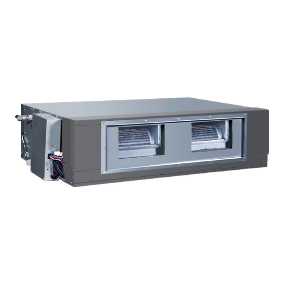
- Page 2 1. Fresh Air Type Indoor Unit 1.1 Features DVFA-140N-01M22 DVFA-280/220N-01M22 Connection condition: The Fresh Air unit can be independently connected with outdoor unit or connected together with common indoor units. The fresh air unit can be installed with common indoor units to introduce outside fresh air into inside room; So it can realize both air-conditioning and fresh-air function in one system. Operation Range: Cooling mode: 19-42°C; Heating mode: -5-18°C; Fan mode: outdoor ambient temp. above 0°C Note: 1. In cooling mode, when inlet temp is lower than 19°C, Fresh Air unit will enter Fan mode automatically; when inlet temp.
- Page 3 The matching rule of Duct Fresh Air. Quantity of Duct fresh air unit Connection method duct fresh Outdoor unit selection Fresh air unit only 10HP DVFA-140N-01M22 Together with general Minimum outdoor capacity 18HP. indoor units Fresh air unit only DVFA-280/220N- Together with general 01M22 Minimum outdoor capacity 28HP. indoor units Fresh air unit only 10HP DVFA-280/220N- Together with general Minimum outdoor capacity 34HP. 01M22 indoor units The matching rule of mixed connection of Duct Fresh Air and general indoor units in one system. ■ Because the return air of Duct Air Fresh is from outside, in which the temperature difference is higher than normal indoor air return type, in order to ensure the cooling/ heating effect, the matching must simultaneously satisfy the following two conditions: 1. C*80%≤A+B≤C*100% (80% total outdoor capacity ≤ total indoor capacity ≤ 100% total outdoor capacity) 2. A≤C*30% (the fresh air capacity ≤ 30% total outdoor capacity) ■ When in mixed installation Only one Duct Fresh Air can be connected in one system.
-
Page 4: Specification
1.2 Specification MODEL DVFA-140N-01M22 DVFA-220N-01M22 DVFA-280N-01M22 Power supply Ph-V-Hz 1,220~230,50/60 1,220~230,50/60 1,220~230,50/60 Capacity kBtu/h 47.7 77.1 95.5 Capacity 22.6 28.0 Cooling Power input Current 3.3 4.0 Capacity kBtu/h 30.4 51.8 60.8 Capacity 15.2 17.8 Heating Power input Current 3.3 4.0 Heating capacity at low temp. 16.5 20.8... - Page 5 MODEL DVFA-140N-01M22 DVFA-220N-01M22 DVFA -280N-01M22 Cabinet coating type Galvanized Galvanized Galvanized Cabinet salt spray test Cabinet Hour 72 72 72 duration Control box IP class IP20 IP20 IP20 Sheet metal thickness Drain pan material Construction Drain pan insulation Drain pump option Branch outlet option Material Hot zinc plate Hot zinc plate Hot zinc plate Indoor wall Thickness Double or single skin Single Single Single Material Air filter Mesh Pressure drop...
- Page 6 1.3 Dimension DVFA-140N-01M22 air outlet air inlet 1200 1355 view A check hole (more than 600*600) 1103 1200 more than 830 view B view C...
- Page 7 DVFA-280/220N-01M22 air inlet air outlet 1510 1570 1725 view A 1622 1572 1510 view B more than 900 1510 check hole (more than 600*600) 1510 1622 view C...
-
Page 8: Piping Diagram
1.4 Piping diagram DVFA-140N-01M22 Liquid pipe Gas pipe Filter Filter Tas (air outlet sensor) Taf (air inlet sensor) Indoor heat exchanger... - Page 9 DVFA-280/220N-01M22...
-
Page 10: Wiring Diagram
1.5 Wiring diagram... -
Page 12: Electric Characteristics
Units Power supply Indoor fan motor Power input (W) Volt Model Phase Voltage Output (W) Cooling Heating range 50/60 198-242 3.25 10.4 265/270 DVFA-140N-01M22 50/60 198-242 326*2 2.25*2 DVFA-280/220N-01M22 50/60 198-242 326*2 2.25*2 DVFA-280/220N-01M22 Symbols: MCA: Min. circuit amps (A) MFA: Max. fuse amps of circuit breaker W: Fan motor rated output (W) FLA: Full load amps Notes: 1. Voltage range The units are applicable for the electrical systems where voltage supplied to unit is in the range. -
Page 13: Air Flow And Static Pressure Curves
1.7 Air flow and static pressure curves DVFA-140N-01M22 2000 1500 1000 50 60 70 80 90 100 110 120 130 140 150 160 170 180 185 Static pressure (Pa) DVFA-280/220N-01M22 3000 2500 2000 1500 1000 50 60 70 80 90 100 110 120 130 140 150 160 170 180 190 200... -
Page 14: Sound Pressure Level
1. The test is on the standard condition. 2. The noise level dB is measured in the semi-anechoic chamber, using a Real Time Analyzer calibrated sound intensity meter. It is a sound pressure noise level. DVFA-140N-01M22 DVFA-280/220N-01M22 Limit of audible... -
Page 15: Installation
1.9 Installation 1.9.1 Installation Procedures The standard attached accessories of the units of this series refer to the packing; prepare other accessories according to the requirements of the local installation point of our company. 1. Before installation [before finishing the installation, don't throw away the attached parts required for the installation] ■ Determine the route to move the unit to the installation site;... - Page 16 DVFA-140N-01M22 DVFA-280/220N-01M22 1100 (3) If necessary, make a hole for installation and inspection on the ceiling. (used for the situation with a ceiling) ■ For the size of the inspection hole on the ceiling, please refer to the above drawing. ■ Before installation, finish all the preparations for all piping connected to indoor units (refrigerant, Water drainage) and wiring (connection line of the wired control, connection line between indoor units and outdoor unit) so that they can be connected with indoor units after installation. ■ For the inspection hole, the ceiling might be reinforced to keep the evenness of the ceiling and avoid the vibration of the ceiling. For details, please consult the construction contractor. Notch grapping Plug (4) Install the suspender (M10 bolts) Notch plug In order to support the weight of the unit, use barb bolts in the situation with a ceiling. In the situation with the new ceiling, use inlaid bolts, embedded bolts or other parts provided on site. Before proceeding the Concrete installation, adjust the gap between the bolt and the ceiling. Hoisting stud M10 (5) Installation of Indoor Units Hoisting stud ...
- Page 17 4. Drainpipes (a) Keep a gradient (1/50-1/100) of the drainpipes and avoid lobbing or curving. ■ Proper Piping ■ Proper Piping (b) When connecting the drainpipe to the equipment, don't apply too much force on one side of the equipment. Meanwhile, the piping should be positioned as close to the equipment as possible. (c) For the drainpipe, the general purpose hard PVC tube can be purchased at local shops. During the connection, insert the end of PVC tube into the wash port and fasten it with drainage hose and thread clip. Binding agents shouldn't be used to connect the wash port and drainage hose. Wash port Drainage hose Wash port Master unit Drainage hose Thread clip Binding S (accessory) (d) When the laid drain piping is used for multiple equipments, the public piping should be lower about 100mm than the wash ports of equipments, as shown in the figure. Thicker pipes should be used for this application.
- Page 18 (e) The hard PVC tube in the room must be provided with the heat insulating layer. (f) Water trap: Because it is easy to cause minus pressure at the water drainage hole, once the water level in drainage pan goes up, water will leak. To prevent water leakage, we design a water trap here. Water trap should be easy to be cleaned. Adopt T-shape connector like below figure. It should be near the unit, as the figure, it is set at the middle of drainage hose. Indoor (g) Don't place the drainpipes at the places where there is irritant gas. Don't put the drainpipe directly into the sewer, where there might be gases with sulfur. Testing Drainage System (a) After finishing the electrical system, test the drainage system. (b) During testing, make sure that the water flow passes the piping correctly without any water leakage at the connection.
- Page 19 ■ The length difference between pipes should be limited to be less than 2:1; ■ Make the piping as short as possible; ■ Keep the min. elbow quantity; Incorrect Incorrect Correct ■ Wind the heat insulating material around the flange between the master unit and the exhaust pipe for heat insulation and sealing. Install the piping before fitting up the ceiling. 6. Calculation of simple duct Assume the friction resistance per unit is 1Pa/m, when the size of one side of air pipe is 25omm, like below figure: Unit Gas pipe Flux (mmxmm) 1200m 250×310 (20m /min) 300m Static pressure box With filter 250×120 /min) ■ Calculation of resistance in duct: ■ Simple duct selection Note:1Pa/m Shape Square Pipe...
- Page 20 7. Cautions in Installation of Air Return Pipe & Exhaust Pipe Special exhaust port Positioning with bolt ■ It is recommended to use the blast pipes, which can be anti-condensation and absorb sound. (purchased at local shops) ■ Complete the installation of the blast pipes before fitting up the suspended ceiling. ■ Heat insulation should be made for the blast pipes. ■ The special exhaust port should be arranged at the place where the air is Blast pipe distributed evenly. ■ An inspection hole should be left on the surface of the ceiling for future maintenance. 8. Examples for Bad Installation ■ The unit is not equipped with the air return pipe and the inner side of the suspending ceiling is used as the blast ...
- Page 21 Pipe Materials & Specifications Model DVFA-140N-01M22 DVFA-280/220N-01M22 Gas Pipe Φ15.88 Φ25.4 Pipe Size (mm) Liquid Pipe Φ9.52 Φ9.52 Pipe Material Phosphor deoxy bronze seamless pipe (TP2) for air conditioner Refrigerant Recharge Amount Recharge the refrigerant according to the installation instruction of outdoor unit. The addition of R410A refrigerant must be performed with a measure gage to ensure the specified amount or compressor failure can be caused by too much or less refrigerant. Connecting Procedures of Refrigerant Tubing Proceed the flare tube connecting operation to connect all the refrigerant tubes. ■ Dual wrenches must be used in the connection of indoor unit tubing. ■ Mounting torque refers to the right table Outer diameter of tubing (mm) Mounting torque Φ9.52 40~50N.m Φ15.88 90~120N.m Φ19.05 100~140N.m Φ25.4 Cutting and Enlarging Connecting Cutting or enlarging pipes should be proceeded by 1. Connecting circular terminals: installation personnel according to the operating ...
-
Page 22: Electrical Wiring
1.9.2 Electrical Wiring WARNING ■ Electrical construction should be made with specific mains circuit by qualified personnel according to installation instruction. Electric shock and fire may be caused if the capacity of power supply is not sufficient. ■ During arranging wiring layout, specified cables should be used as mains line, which accords with local regulations on wiring. Connecting and fastening should be performed reliably to avoid external force of cables from transmitting to the terminals. Improper connection or fastness may lead to burning or fire accidents. ■ There must be the ground connection according to the criterion. Unreliable grounding may cause electrical shocks. Do not connect the grounding line to the gas pipe, water pipe, lightening rod and telephone line. ATTENTIoN ■ Only copper wire can be used. Breaker for electric leakage should be provided, or electric shock may occur. ■ The wiring of the mains line is of Y type. The power plug L should be connected to the live wire and plug N connected to null wire while should be connected to the ground wire. For the type with auxiliary electrically heating function, the live wire and the null wire should not be misconnected, or the surface of electrical heating body will be electrified. If the power line is damaged, replace it by the professional personnel of the manufacturer or service center. ■ The power line of indoor units should be arranged according to the installation instruction of indoor units. ■ The electrical wiring should be out of contact with the high-temperature sections of tubing as to avoid melting the insulating layer of cables, which may cause accidents. ■ After connected to the terminal tier, the tubing should be curved into be a U-type elbow and fastened with the pressing clip. ■ Controller wiring and refrigerant tubing can be arranged and fixed together. - Page 23 Signal Wiring Drawing Outdoor 1 Outdoor 2 Outdoor 3 Indoor 1 Indoor 2 Indoor 3 Indoor 4 Indoor 5 Outdoor units are of parallel connection via three lines with polarity. The master unit, central control and all indoor units are of parallel connection via two lines without polarity. The singal line between wired controller and indoor units are polarity There are three connecting ways between wired controller and indoor units: A. One wired controller controls one indoor unit, the wired controller connects with the ABC terminal of indoor unit. Indoor Wired controller B. Two wired controllers control one indoor unit. Either of the wired controls can be set to be the master wired controller while the other is set to be the slave wired controller. Indoor Wired Wired controller controller Master and slave controller setting method for YR-E17, other controllers' setting method please refer to the controller manual Type State of switch...
- Page 24 C. One wired controller controls multiple units 0151800113 PCB Note: 1. The wired controller connects with the ABC terminal of master unit which wired address is 0, the slave unit only connects BC terminal. 2. Wired address setting Wired control address oFF oFF oFF oFF Master unit in group control SW01_1 OFF OFF OFF Slave unit 1 in group control SW01_2 Wired control address OFF OFF Slave unit 2 in group control SW01_3 OFF OFF Slave unit 3 in group control SW01_4 … … … … …… Slave unit 15 in group control 3. One controller can Max. control 16 indoor units. 4. Hand-in-hand connection method 5. The singal line is polarity...
- Page 25 Indoor power supply wiring & signal wiring between indoor and outdoor & signal wiring between indoor. Items Cross sectional Rated Rated current of residual circuit Cross area of signal Line Length current of breaker (A) Total section overflow Ground fault Interrupter (mA) Outdoor Indoor current of breaker (A) Response time (S) -indoor (mm -indoor (mm indoor units (A) <7 10 A, 30 mA, 0.1S or below ≥7 and <11 16 A, 30 mA, 0.1S or below 2 cores×(0.75-2.0) ≥11 and <16 20 A, 30 mA, 0.1S or below shielded line ≥16 and <22 32 A, 30 mA, 0.1S or below ≥22 and <27 32 A, 30 mA, 0.1S or below ※ The electrical power line and signal lines must be fastened tightly. ※ Every indoor unit must have the ground connection. ※ The power line should be enlarged if it exceeds the permissible length. ※ Shielded lays of all the indoor and outdoor units should be connected together, with the shielded lay at the side of signal lines of outdoor units grounded at one point. ※ It is not permissible if the whole length of signal line exceeds 1000m. Signal wiring of wired controller Length of signal line (m) Wiring dimensions...
- Page 26 1.9.3 Test Run Before Test Run ■ Before switching it on, test the supply terminal tier (L, N terminals) and grounding points with 500V megaohm meter and check if the resistance is above 1MΩ. It can't be operated if it is below 1MΩ. ■ Connect it to the power supply of outdoor units to energize the heating belt of the compressor. To protect the compressor at startup, power it on 12 hours prior to the operation. Check if the arrangements of the drainpipe and connection line are correct. The drainpipe shall be placed at the lower part while the connection line placed at the upper part. Heat preservation measures should be taken such as winding the drainpipe esp. in the indoor units with heating insulating materials. The drain pipe should be made a slope type to avoid protruding at the upper part and concaving at the lower part on the way. Checkup of Installation Check if the installation place meets the requirement Check if the mains voltage is matching Check if there is too much noise Check if there is air leakage at the piping joints Check if the connecting line is fastened Check if the connections of mains power Check if the connectors for tubing are heat insulated and indoor & outdoor units are correct Check if the water is drained to the outside Check if the serial numbers of terminals are Matching Check if the indoor units are positioned Ways of Test Run Do ask the installation personnel to make a test run. Take the testing procedures according to the manual and check if the temperature regulator works properly. When the machine fails to start due to the room temperature, the following procedures can be taken to do the compulsive running. The function is not provided for the type with remote control. ■ Set the wired controller to cooling/heating mode, press "ON/OFF" button for 5 seconds to enter into the compulsive cooling/heating mode. Repress "ON/OFF" button to quit the compulsive running and stop the operation of the air conditioner.
- Page 27 Consult with the sales agency or manufacturer for details. ATTENTION : Le design et les données techniques sont donnés à titre indicatif et peuvent être modifiés sans préavis. AIRWELL RESIDENTIAL SAS 10,Rue du Fort de Saint Cyr, 78180 Montigny le Bretonneux - France www.airwell.com...
Need help?
Do you have a question about the DVFA-140N-01M22 and is the answer not in the manual?
Questions and answers