Table of Contents
Advertisement
Quick Links
TECHNICAL Manual
MIDDLE STATIC PRESSURE DUCT AIR CONDITIONER
DFMA R410A ON OFF 50Hz
English Manual
DFMD-100N-01M25
DFMD-100N-01T35
DFMD-140N-01M25
DFMD-160N-01M25
IMPORTANT NOTE:
Read this manual carefully before installing or operating your new air conditioning unit. Make sure to
save this manual for future reference.
21.AW.DFMD.100-160.R410A.TM.EN.11.19.Rev01
/
YFAD-100R-01M25
/
YFAD-100R-01T35
/
YFAD-140R-01M25
/
YFAD-160R-01M25
Advertisement
Chapters
Table of Contents

Related Manuals for Airwell DFMD-100N-01M25


Summary of Contents for Airwell DFMD-100N-01M25
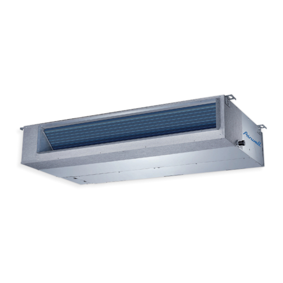
- Page 1 TECHNICAL Manual MIDDLE STATIC PRESSURE DUCT AIR CONDITIONER DFMA R410A ON OFF 50Hz English Manual DFMD-100N-01M25 YFAD-100R-01M25 DFMD-100N-01T35 YFAD-100R-01T35 DFMD-140N-01M25 YFAD-140R-01M25 DFMD-160N-01M25 YFAD-160R-01M25 IMPORTANT NOTE: Read this manual carefully before installing or operating your new air conditioning unit. Make sure to save this manual for future reference.
-
Page 2: Table Of Contents
Table of Contents Page 1. Specifications ....................4 Model Reference General Specifications Dimensional Drawings Centre of Gravity Electrical Wiring Diagrams Refrigerant Cycle Diagrams Capacity Tables Capacity Correction Factor for Height Difference Noise Data Electrical Characteristics Static Pressure 2. Product Features ................... 58 Operation Modes and Functions Remote Controller Functions 3. - Page 3 Table of Contents Page 4. Static Pressure Design .................. 91 Introduction Charts for friction losses in round ducts Dynamic losses Corresponding relation between Rectangular duct and Round duct Method for duct calculation Unit conversion Recommended outlet velocity for different occasions...
-
Page 4: Specifications
Specifications Contents Model Reference....................5 General Specifications...................6 Dimensional Drawings ..................12 Centre of Gravity ....................15 Electrical Wiring Diagrams..................18 Refrigerant Cycle Diagrams ................31 Capacity Tables ....................33 Capacity Correction Factor for Height Difference ..........48 Noise Data......................53 Electrical Characteristics..................55 Static Pressure......................56... -
Page 5: Model Reference
Refer to the following table to determine the specific indoor and outdoor unit model number of your purchased equipment. Indoor Unit Model Outdoor Unit Model Capacity (Btu/h) Power Supply 1Φ, 220~240V~, 50Hz DFMD-100N-01M25 YFAD-100R-01M25 3Φ, 380~415V~, 50Hz DFMD-100N-01T35 YFAD-100R-01T35 3Φ, 380~415V~, 50Hz DFMD-140N-01M25 YFAD-140R-01M25 3Φ, 380~415V~, 50Hz... -
Page 6: General Specifications
2. General Specifications DFMD-100N-01T35 Indoor model Outdoor model YFAD-100R-01T35 220-240,50,1 Power Supply V-Ph-Hz 5200 Max. input consumption 23.0 Max. input current YKSS-115-4-21 Model Insulation class IPX0 Indoor fan motor IP rating 253.0 Input Capacitor 1110/1000/910/780 Speed(Hi/Mi/Lo) r/min Number of rows 21x13.37 Tube pitch(a)x row pitch(b) Fin spacing... - Page 7 YKS-190-6-21L Model Insulation class Outdoor fan IPX4 IP rating motor 293.3 Input 10/450V Capacitor 850/770 Speed r/min Number of rows 25.4x22 Tube pitch(a)x row pitch(b) Fin spacing Hydrophilic aluminum Fin type (code) Outdoor coil 9.52,Inner groove tube Tube outside dia.and type 995x762x44 Coil length x height x width Number of circuits...
- Page 8 Indoor model DFMD-100N-01T35 DFMD-140N-01M25 Outdoor model YFAD-100R-01T35 YFAD-140R-01T35 Power Supply V-Ph-Hz 380~415,50,3 380~415,50,3 Max. input consumption 4250 6300 Max. input current Model YKSS-115-4-21 YKSS-210-4-2 Insulation class Indoor fan motor IP rating IPX0 IPX0 Input Capacitor Speed(Hi/Mi/Lo) r/min 1110/1000/910/780 930/860/760 Number of rows Tube pitch(a)x row pitch(b) 21x13.37 21x13.37...
- Page 9 Number of rows Tube pitch(a)x row pitch(b) 25.4x22 22x19.05 Fin spacing Outdoor coil Fin type (code) Hydrophilic aluminum Hydrophilic aluminum Tube outside dia.and type Φ9.52,Inner groove tube Ф7.94,Inner groove tube Coil length x height x width 995x762x44 837x1100x38.1 Number of circuits Outdoor noise level dB(A) Throttle type...
- Page 10 Indoor model DFMD-160N-01M25 Outdoor model YFAD-160R-01T35 380~415,50,3 Power Supply V-Ph-Hz 7500 Max. input consumption 12.6 Max. input current YKSS-210-4-2 Model Insulation class IPX0 Indoor fan motor IP rating Input Capacitor 930/860/760 Speed(Hi/Mi/Lo) r/min Number of rows 21x13.37 Tube pitch(a)x row pitch(b) Fin spacing Hydrophilic aluminium Indoor coil...
- Page 11 Number of rows 21x22 Tube pitch(a)x row pitch(b) Fin spacing Hydrophilic aluminum Fin type (code) Outdoor coil Ф7,Inner groove tube Tube outside dia.and type 830*22*630+795*22*630+830*22*483+ Coil length x height x width 795*22*483 Number of circuits 62.8 Outdoor noise level dB(A) Throttle valve Throttle type 900x350x1170...
-
Page 12: Dimensional Drawings
3. Dimensional Drawings Indoor Unit Model unit (KBtu/h) inch 34.65 8.27 26.54 25.98 5.51 27.80 1.97 5.35 30.79 7.48 1.57 36.22 3.07 5.83 3.46 4.41 1100 1001 1140 24-36 inch 43.31 9.80 30.47 27.56 5.51 36.46 1.97 6.89 39.41 8.98 44.88 11.73 3.15... - Page 13 Outdoor Unit Single Fan Outdoor Unit Model(KBtu/h) unit inch 30.31 11.81 21.85 33.07 19.17 11.73 inch 33.27 14.29 27.64 35.98 21.26 13.78 1030 inch 37.24 16.14 31.89 40.55 26.50 15.87 Page 13 ...
- Page 14 Double Fan Outdoor Unit Model (KBtu/h) unit 1170 48/60 inch 35.43 13.78 46.06 38.78 23.23 14.88 Page 14 ...
-
Page 15: Centre Of Gravity
4. Centre of gravity Page 15 ... - Page 16 Page 16 ...
- Page 17 48K, 60K Page 17 ...
-
Page 18: Electrical Wiring Diagrams
5. Electrical Wiring Diagrams Indoor unit Abbreviation Paraphrase Yellow-Green Conductor CAP1 Indoor Fan Capacitor Indoor Fan PUMP PUMP LIVE NEUTRAL TO CCM Comm.Bus Central Controller Indoor Room Temperature Coil Temperature of Indoor Heat Exchanger Super High Speed High Speed Page 18 ... - Page 19 DFMD-100N-01M25 Page 19 ...
- Page 20 DFMD-100N-01T35 Page 20...
- Page 21 DFMD-140N-01M25 FAN FOR THE FRESH AIR Alarm Remote OR ANION Output GENERATOR Control ALARM ON/OFF PUMP CN43 CN33 CN23 CN13 WIRE DISPLAY CN10 BOARD CONTROLLER INDOOR UNIT INDOOR COIL TEMP. SENSOR BLACK MAINBOARD WHITE ROOM TEMP. SENSOR CN111 CN40 BLACK To CCM Comm.Bus ...
- Page 22 DFMD-160N-01M25 Page 22 ...
- Page 23 Some connectors introduce: A. For new fresh motor terminal port (also for Anion generator) CN43: 1. Connect the fan motor to the port , no need care L/N of the motor ; 2. The output voltage is the power supply; 3.
- Page 24 B For ALARM terminal port CN33 1. Provide the terminal port to connect ALARM ,but no voltage of the terminal port , the power from the ALARM system (not from the unit ) 2. Althought design voltage can support higher voltage ,but we strongly ask you connect the power less than 24V, current less than 0.5A 3.
- Page 25 C. For remote control (ON-OFF) terminal port CN23 and short connector of J7 1. Remove the short connector of J7 when you use ON-OFF function; 2. When remote switch off (OPEN) ;the unit would be off; 3. When remote switch on (CLOSE) ;the unit would be on; 4.
- Page 26 Outdoor Unit Abbreviation Paraphrase CAP1, CAP2, CAP3,CAP4 Capacitor FAN1 Outdoor Fan Motor Contactor CT1, CT2 AC Current Detector COMP Compressor L-PRO, K2 Low Pressure Switch/Shorting Stub High Pressure Switch/Shorting Stub TRANS Power Transformer 10KΩ RESISTANCE/Outdoor Ambient Temperature 10KΩ RESISTANCE/Coil Temperature of Condenser 2-Way Terminal/4-Way Terminal 3-Way Terminal Terminal...
- Page 27 YFAD-100R-01M25 Page 27 ...
- Page 28 YFAD-100R-01T35 Page 28 ...
- Page 29 YFAD-140R-01T35 Page 29 ...
- Page 30 YFAD-160R-01T35 Page 30 ...
-
Page 31: Refrigerant Cycle Diagrams
6. Refrigerant Cycle Diagrams Heat pump Pipe Size(Diameter:ø) Piping length(m/ft) Elevation(m/ft) mm(inch) Model No. Additional Refrigerant Liquid Rated Max. Rated Max. YFAD-100R-01M25 19(3/4) 9.52(3/8) 5/16.4 30g/m (0.32oz/ft) 30/98.4 20/65.6 YFAD-100R-01T35 19(3/4) 9.52(3/8) 5/16.4 30/98.4 20/65.6 30g/m (0.32oz/ft) Page 31 ... - Page 32 Pipe Size (Diameter:ø) Piping length(m/ft) Elevation(m/ft) mm(inch) Model No. Additional Refrigerant Liquid Rated Max. Rated Max. YFAD-140R-01T35 19(3/4) 9.52(3/8) 5/16.4 30g/m (0.32oz/ft) 50/164 30/98.4 YFAD-160R-01T35 19(3/4) 9.52(3/8) 5/16.4 30g/m (0.32oz/ft) 50/164 30/98.4 Page 32 ...
-
Page 33: Capacity Tables
7. Capacity Tables Cooling DFMD-100N-01M25+YFAD-100R-01M25 ID WB 16.0 18.0 19.0 22.0 INDOOR OUT- (℃) AIRFLOW DOOR ID DB (CMH) DB(℃) 23.0 25.0 27.0 29.0 23.0 25.0 27.0 29.0 23.0 25.0 27.0 29.0 23.0 25.0 27.0 29.0 (℃) 10.66 10.67 10.67 10.78... - Page 34 ID WB 16.0 18.0 19.0 22.0 INDOOR OUT- (℃) AIRFLOW DOOR ID DB (CMH) DB(℃) 23.0 25.0 27.0 29.0 23.0 25.0 27.0 29.0 23.0 25.0 27.0 29.0 23.0 25.0 27.0 29.0 (℃) 11.08 11.19 11.31 11.43 11.74 11.74 11.74 11.86 12.08 12.08 12.08...
- Page 35 DFMD-100N-01M25+YFAD-100R-01M25 ID WB 16.0 18.0 19.0 22.0 INDOOR OUT- (℃) AIRFLOW DOOR ID DB (CMH) DB(℃) 23.0 25.0 27.0 29.0 23.0 25.0 27.0 29.0 23.0 25.0 27.0 29.0 23.0 25.0 27.0 29.0 (℃) 10.66 10.67 10.67 10.67 11.30 11.54 11.54 11.54...
- Page 36 ID WB 16.0 18.0 19.0 22.0 INDOOR OUT- (℃) AIRFLOW DOOR ID DB (CMH) DB(℃) 23.0 25.0 27.0 29.0 23.0 25.0 27.0 29.0 23.0 25.0 27.0 29.0 23.0 25.0 27.0 29.0 (℃) 11.08 11.08 11.19 11.31 11.74 11.74 11.74 11.86 12.08 12.08 12.08...
- Page 37 DFMD-100N-01T35+YFAD-100R-01T35 ID WB 16.0 18.0 19.0 22.0 INDOOR OUT- (℃) AIRFLOW DOOR ID DB (CMH) DB(℃) 23.0 25.0 27.0 29.0 23.0 25.0 27.0 29.0 23.0 25.0 27.0 29.0 23.0 25.0 27.0 29.0 (℃) 10.66 10.67 10.67 10.78 11.30 11.54 11.54 11.54 11.61 11.61...
- Page 38 ID WB 16.0 18.0 19.0 22.0 INDOOR OUT- (℃) AIRFLOW DOOR ID DB (CMH) DB(℃) 23.0 25.0 27.0 29.0 23.0 25.0 27.0 29.0 23.0 25.0 27.0 29.0 23.0 25.0 27.0 29.0 (℃) 11.08 11.19 11.31 11.43 11.74 11.74 11.74 11.86 12.08 12.08 12.08...
- Page 39 DFMD-140N-01M25 ID WB 16.0 18.0 19.0 22.0 INDOOR OUT- (℃) AIRFLOW DOOR ID DB (CMH) DB(℃) 23.0 25.0 27.0 29.0 23.0 25.0 27.0 29.0 23.0 25.0 27.0 29.0 23.0 25.0 27.0 29.0 (℃) 14.18 14.16 14.16 14.16 15.02 15.35 15.35 15.35 15.45 15.45...
- Page 40 ID WB 16.0 18.0 19.0 22.0 INDOOR OUT- (℃) AIRFLOW DOOR ID DB (CMH) DB(℃) 23.0 25.0 27.0 29.0 23.0 25.0 27.0 29.0 23.0 25.0 27.0 29.0 23.0 25.0 27.0 29.0 (℃) 14.78 14.78 14.93 15.07 15.67 15.67 15.67 15.67 16.12 16.12 16.12...
- Page 41 DFMD-160N-01M25 ID WB 16.0 18.0 19.0 22.0 INDOOR OUT- (℃) AIRFLOW DOOR ID DB (CMH) DB(℃) 23.0 25.0 27.0 29.0 23.0 25.0 27.0 29.0 23.0 25.0 27.0 29.0 23.0 25.0 27.0 29.0 (℃) 16.27 16.27 16.27 16.27 17.24 17.60 17.60 17.60 17.72 17.72...
- Page 42 ID WB 16.0 18.0 19.0 22.0 INDOOR OUT- (℃) AIRFLOW DOOR ID DB (CMH) DB(℃) 23.0 25.0 27.0 29.0 23.0 25.0 27.0 29.0 23.0 25.0 27.0 29.0 23.0 25.0 27.0 29.0 (℃) 16.94 16.94 17.12 17.29 17.95 17.95 17.95 17.95 18.46 18.46 18.46...
- Page 43 Heating DFMD-100N-01M25+FFMD-100N-01M25 [SI_Unit] HEATING PERFORMANCE AT INDOOR DRY BULB TEMPERATURE INDOOR TC:TOTAL CAPACITY IN KILOWATTS (KW) PI:TOTAL POWER IN KILOWATTS (KW) OUTDOOR AIRFLOW Indoor Conditions (DB °C ) Indoor Conditions (DB °C ) (CMH) DB(°C) 16.0 20.0 22.0 24.0 16.0 20.0...
- Page 44 DFMD-100N-01M25+YFAD-100R-01M25 [SI_Unit] HEATING PERFORMANCE AT INDOOR DRY BULB TEMPERATURE INDOOR TC:TOTAL CAPACITY IN KILOWATTS (KW) PI:TOTAL POWER IN KILOWATTS (KW) OUTDOOR AIRFLOW Indoor Conditions (DB °C ) Indoor Conditions (DB °C ) (CMH) DB(°C) 16.0 20.0 22.0 24.0 16.0 20.0 22.0...
- Page 45 DFMD-100N-01T35+YFAD-100R-01T35 [SI_Unit] HEATING PERFORMANCE AT INDOOR DRY BULB TEMPERATURE INDOOR TC:TOTAL CAPACITY IN KILOWATTS (KW) PI:TOTAL POWER IN KILOWATTS (KW) OUTDOOR AIRFLOW Indoor Conditions (DB °C ) Indoor Conditions (DB °C ) (CMH) DB(°C) 16.0 20.0 22.0 24.0 16.0 20.0 22.0 24.0 -7.0...
- Page 46 DFMD-140N-01M25+YFAD-140R-01T35 [SI_Unit] HEATING PERFORMANCE AT INDOOR DRY BULB TEMPERATURE INDOOR TC:TOTAL CAPACITY IN KILOWATTS (KW) PI:TOTAL POWER IN KILOWATTS (KW) OUTDOOR AIRFLOW Indoor Conditions (DB °C ) Indoor Conditions (DB °C ) (CMH) DB(°C) 16.0 20.0 22.0 24.0 16.0 20.0 22.0 24.0 -7.0...
- Page 47 DFMD-160N-01M25 [SI_Unit] HEATING PERFORMANCE AT INDOOR DRY BULB TEMPERATURE INDOOR TC:TOTAL CAPACITY IN KILOWATTS (KW) PI:TOTAL POWER IN KILOWATTS (KW) OUTDOOR AIRFLOW Indoor Conditions (DB °C ) Indoor Conditions (DB °C ) (CMH) DB(°C) 16.0 20.0 22.0 24.0 16.0 20.0 22.0 24.0 -7.0...
-
Page 48: Capacity Correction Factor For Height Difference
8. Capacity Correction Factor for Height Difference Heat pump models Model Pipe Length (m) Cooling Indoor 0.915 0.861 Upper than 0.957 0.929 0.874 Outdoor 0.995 0.967 0.939 0.883 Height difference 1.000 0.972 0.944 0.887 H (m) 1.000 0.972 0.944 0.887 Outdoor 0.972 0.944... - Page 49 Model Pipe Length (m) Cooling Indoor 0.900 0.830 Upper than 0.949 0.914 0.842 Outdoor 0.995 0.959 0.923 0.851 Height difference 1.000 0.964 0.928 0.855 H (m) 1.000 0.964 0.928 0.855 Outdoor 0.964 0.928 0.855 Upper than 0.928 0.855 Indoor Heating Indoor 0.973 0.946...
- Page 50 Model Pipe Length (m) Cooling 0.820 0.775 0.729 Indoor 0.878 0.832 0.786 0.740 Upper than 0.938 0.892 0.845 0.798 0.752 Outdoor 0.995 0.948 0.901 0.854 0.806 0.759 Height difference 1.000 0.953 0.905 0.858 0.810 0.763 H (m) 1.000 0.953 0.905 0.858 0.810 0.763...
- Page 51 Model Pipe Length (m) Cooling 0.808 0.749 0.690 Indoor 0.880 0.820 0.760 0.701 Upper than 0.955 0.894 0.833 0.772 0.711 Outdoor 0.995 0.964 0.903 0.841 0.780 0.718 Height difference 1.000 0.969 0.907 0.846 0.784 0.722 H (m) 1.000 0.969 0.907 0.846 0.784 0.722...
- Page 52 Model Pipe Length (m) Cooling 0.772 0.698 0.625 Indoor 0.858 0.784 0.709 0.634 Upper than 0.947 0.871 0.796 0.720 0.644 Outdoor 0.995 0.957 0.880 0.804 0.727 0.650 Height difference 1.000 0.962 0.885 0.808 0.731 0.654 H (m) 1.000 0.962 0.885 0.808 0.731 0.654...
- Page 53 -Sound level will vary depending on a range of factors such as the construction -(acoustic absorption coefficient) of particular room in which the equipment is installed. -The operating conditions are assumed to be standard. Noise level dB(A) Model DFMD-100N-01M25 40.5 DFMD-100N-01T35 DFMD-140N-01M25 DFMD-160N-01M25 ...
- Page 54 Outdoor Unit Note: H= 0.5 × height of outdoor unit Notes: -Sound measured at 1.0m away from the center of the unit. -Data is valid at free field condition -Data is valid at nominal operation condition -Reference acoustic pressure OdB=20μPa -Sound level will vary depending on arrange off actors such as the construction (acoustic absorption coefficient) of particular room in which the equipment is installed.
-
Page 55: Electrical Characteristics
10. Electrical Characteristics 10.1 Heat pump models Type 18000 Btu/h 24000 Btu/h 36000 Btu/h Phase 1-phase 1-phase 1-phase Frequency and Voltage 220-240V, 50Hz 220-240V~,50Hz 220-240V, 50Hz Circuit Breaker/ Fuse (A) 25/20 32/25 50/40 Indoor Unit Power Wiring (mm 3×2.5 3×2.5 Outdoor Unit Power Wiring (mm 3×4.0 Ground Wiring... -
Page 56: Static Pressure
11. Static Pressure Page 56 ... - Page 57 30K/36K 48K/60K Page 57 ...
-
Page 58: Product Features
Product Features Contents Operation Modes and Functions ................59 Abbreviations ....................59 Safety Features ....................59 Display Function ..................59 Fan......................59 Cooling Mode .....................59 Heating Mode .....................59 Auto Mode....................60 Drying Mode ....................60 Timer Function ....................60 1.10 Sleep Function.....................60 1.11 Auto-Restart....................61 1.12 Follow Me ....................61 1.13 Drain Pump Control..................61 Remote Controller Functions ................62 LCD Wired Remote Controller ..............62... -
Page 59: Operation Modes And Functions
1. Operation Modes and Functions Display Function Unit display functions Abbreviation Unit element abbreviations Abbreviation Element Indoor room temperature Coil temperature of evaporator Coil temperature of condenser Outdoor ambient temperature Compressor discharge temperature When fan mode is activated: Safety Features •... -
Page 60: Auto Mode
1.5.5 Condenser Temperature Protection • In auto mode, the machine selects cooling, heating, or fan-only mode on the basis of △T (△T =T1-Ts). When condenser temperature is more than setting value, the compressor ceases operations. ∆T Running mode ∆T>2℃ Cooling Heating Mode(Heat pump models) -1℃≤∆T≤2℃... -
Page 61: Auto-Restart
• When cooling, the temperature rises 1℃ (to not the water level falls and LED alarm code is no longer higher than 30℃) every hour. After 2 hours, the displayed (drain pump close delay is 1 minute), the temperature stops rising and the indoor fan is fixed to unit goes back into its last mode. -
Page 62: Remote Controller Functions
2. Remote Controller Functions LCD Wired Remote Controller 2.1.1 LCD Wired Remote Controller KJR-12B/DP(T) (Standard) The KJR-12B/DP(T) wired remote controller is standard for Duct type. i) Buttons and Functions MODE BUTTON ON/OFF BUTTON • Used to start/stop the air • Used to select the operating mode conditioner. - Page 63 iii) Installation • Dimensions 120mm 21mm 13.1mm (4.7”) (0.8”) (0.5”) 19.5mm (0.7”) 120mm 85.5mm (4.7”) (3.3”) 50mm (1.9”) • Wiring diagram Refer to the following diagram to wire the wall-mounted remote control to the indoor unit. Wire Joint, 5p Infrared Pipe 5-Core Shield Cable Indoor Unit Switch Board Indoor Unit...
- Page 64 Putty Trap Putty Putty Trap Trap Note: DO NOT allow water to enter the remote control. Use the trap and putty to seal the wires. • For exposed mounting, cut holes on four of the sides according to the picture below. Cut three holes Cut one holes for wire outlet...
- Page 65 2.1.2 LCD Wired Remote Controller KJR-120C/TF-E(Optional) The KJR-120C/TF-E wired remote controller is optional for all types. i) Buttons and Functions ë ï á å Ö ë ï á å Ö 1. POWER button 7. FOLLOW ME(PTC) button Turn on of turn off the unit. Allows the remote control to act as a remote thermostat and send temperature information from its current 2.
- Page 66 ii) LCD Screen 1 Operation mode indication 9 C° / F° indication 2 Fan speed indication 10 Temperature display 3 Left-right swing indication 11 Lock indication 4 Up-down swing indication 12 Room temperature indication 5 Faceplate function indication 13 Clock display 6 Main unit and secondary unit indication 14 On/Off timer 7 Follow me function indication...
- Page 67 iii) Installation • Dimensions 18.5 • Wiring diagram Refer to the following diagram to wire the wall-mounted remote control to the indoor unit. Insert of the mainboard CN40 ----------------------------------- ----------------------------------- black black yellow ----------------------------------- yellow ----------------------------------- brown brown 4-Core Shield Cable, the length Wire controller Indoor unit mainboard is decided by installation...
- Page 68 Putty Trap Putty Putty Trap Trap Note: DO NOT allow water to enter the remote control. Use the trap and putty to seal the wires. • For exposed mounting, four outletting positions. There are three need cutting. Cutting place of right Cutting place of left Cutting place of top side wire outlet...
- Page 69 2.1.3 LCD Wired Remote Controller KJR-120G/TF-E(Optional) The KJR-120G/TF-E wired remote controller is optional for all types. i) Buttons and Functions Copy/ Swing Timer Back/Turbo Follow me Mode Fan speed (Lock) MODE button 6. TIMER button Used to select the operation mode: Auto / Cooling / Drying / To set timer on and timer off time of one day Heating / Fan;...
- Page 70 ii) LCD Screen 1 Operation mode indication 8 Turbo/PTC function indication 2 Fan speed indication 9 C° / F° indication 3 Left-right swing indication 10 Temperature display 4 Up-down swing indication 11 Lock indication 5 Faceplate function indication 12 Room temperature indication 6 Main unit and secondary unit indication 13 Clock display 7 Follow me function indication...
- Page 71 iii) Installation • Dimensions 120mm 18.5mm 46mm (4.7”) (0.7”) (1.8”) 83.5mm 123mm (3.3”) (4.8”) 62mm (2.4”) • Wiring diagram 1) Connection For Cassette: The wired controller connects to main control board directly. Main control board ADSS HA HB HA HB Wired controller For Duct, Ceiling&...
- Page 72 2) Address setting Unit1 Unit2 Unit16 HA HB HA HB HA HB HA HB Wired controller a. One non-polarity controller can control up to 16 indoor units. b. When the non-polarity controller is connected to several units, every air-conditioner in network has only one network address to distinguish each other.
- Page 73 Putty Trap Putty Putty Trap Trap Note: DO NOT allow water to enter the remote control. Use the trap and putty to seal the wires. • For wiring the indoor unit, there are three methods: • From the rear; • From the bottom; •...
-
Page 74: Centralized Controller
Centralized Controller 1) Connection For Light commercial air conditioner with XYE port, it can be directly connected to Centralized Controller (CCM03, CCM09). 2) Address setting When setting the address, please make sure the unit is powered off. The address can be set from 0 to 63 by the switch. Turn on the unit, then the address will be effective. - Page 75 Installation Accessories ........................76 Installation Overview..................77 Location Selection ....................78 Indoor Unit Installation..................79 Outdoor Unit Installation..................82 Drainage Pipe Installation...................83 Refrigerant Pipe Installation................86 Vacuum Drying and Leakage Checking..............87 Additional Refrigerant Charge ................88 Engineering of Insulation ...................88 Engineering of Electrical Wiring................89 Test Operation .....................90...
-
Page 76: Accessories
Accessories Name Shape Quantity Soundproof / insulation sheath Tubing & Fittings Seal sponge (some models) Orifice (some models) Drain joint (some models) Drainpipe Fittings (for cooling & heating) Seal ring (some models) Magnetic ring(Wrap the electric wires S1 & S2 ( P &... -
Page 77: Installation Overview
1. Installation Overview Installation Order Install the indoor unit Install the outdoor unit Connect the refrigerant pipes Evacuate the refrigeration system Connect the wires Install the drainpipe Perform a test run Page 77 ... -
Page 78: Location Selection
2. Location selection Unit location selection can refer to installation manual. DO NOT install the unit in the following locations: • Where oil drilling or fracking is taking place. • Coastal areas with high salt content in the air. • Areas with caustic gases in the air, such as near hot springs. -
Page 79: Indoor Unit Installation
3. Indoor Unit Installation positions in the internal ceiling. Be sure to hold the drill at a 90° angle to the ceiling. Service space for indoor unit 6. Secure the bolt using the included washers and nuts. 7. Install the four suspension bolts. 30cm or more 20cm or more 8. - Page 80 5. Refer to the following static pressure guidelines when Ventilation panel installing the indoor unit. Model(KBtu/h) Static Pressure(Pa) 18~24 0-80 30~36 0-100 48~60 0-160 Change the fan motor static pressure according to external Air return flange duct static pressure. NOTE: 1. Do not put the connecting duct weight on the indoor unit.
- Page 81 18-60k Ø125mm(4.92”) Ø160mm(6.3”) Connector A Connector D Connector B Connector C Hose 3.6 Horizontal Installation Plug the external pump to the “PUMP” pin and the water 3.6.1 With External pump (9K, 12K models) level sensor to the “CN5” to enable the pump. Cut both ends of the rubber hose into a straight one, use Remove the it to connect the drain Connector A and the external...
-
Page 82: Outdoor Unit Installation
Bolt pitch When installed vertically (up flow), the pump must be disabled firstly. Follow the 3.7.1 steps to disable the pump. For the unit with external pump (9K ,12K &18K models), the whole pump assembly can be removed. Then take the cap on drain connector off and connect the drainpipe to drain connector . -
Page 83: Drainage Pipe Installation
5. Drainage Pipe Installation For Vertical drainage pipe (The following table is for reference) Install the drainage pipe as shown below and take measures against condensation. Improperly installation Reference could lead to leakage and eventually wet furniture and Allowable value of inner belongings. - Page 84 ing pipe. • Each indoor unit of the system should be installed it. • The installation should be considering the conve- nience for future cleaning. • The correct installation will not cause converse water flow and the slope of the branch pipes can be adjusted freely •...
- Page 85 Insulation work of drainage pipe Refer the introduction to the insulation engineering parts. Test cap Stow tube 2. Turn on the unit in COOLING mode. You will hear the drain pump.Check whether the water is discharged properly (a 1-minute lag is possible, depending on the length of the drain pipe), Check whether water leaks from the joints.
-
Page 86: Refrigerant Pipe Installation
6. Refrigerant Pipe Installation 3.Measure the necessary pipe length. 4.Cut the selected pipe with pipe cutter Maximum length and drop height • Make the section flat and smooth. Ensure that the length of the refrigerant pipe, the number of bends, and the drop height between the indoor and 90°... -
Page 87: Vacuum Drying And Leakage Checking
• and keep vacuum pump running for 1hour (vacuum Be sure to use two spanners and proper torque to degree of vacuum pump shall be reached -755mmHg). fasten the nut, too large torque will damage the bellmouthing, and too small torque may cause 2. -
Page 88: Additional Refrigerant Charge
8. Additional Refrigerant Charge 9. Engineering of Insulation • After the vacuum drying process is carried out, the additional refrigerant charge process need to be Insulation of refrigerant pipe performed. • 1. Operational procedure of refrigerant pipe The outdoor unit is factory charged with refrigerant. insulation The additional refrigerant charge volume is decided by the diameter and length of the liquid pipe be-... -
Page 89: Engineering Of Electrical Wiring
10. Engineering of Electrical Wiring insulation and cause easy aging of the material. Insulation of drainage pipe 10.1 Highlights of electrical wiring installation 1. Operational procedure of refrigerant pipe insulation • All field wiring construction should be finished by qualified electrician. Select the suitable pipe →... -
Page 90: Test Operation
11. Test Operation 4. Drainage Test a. Ensure the drainpipe flows smoothly. New buildings 11.1 The test operation must be carried out should perform this test before finishing the ceiling. after the entire installation has been b. Remove the test cover. Add 2000ml of water to the tank completed. - Page 91 Static Pressure Design Introduction .......................95 Charts for friction losses in round ducts ............95 Dynamic losses....................96 Corresponding relation between Rectangular duct and Round Duct ...97 Method for duct calculation ................98 Unit conversion....................98 Recommended outlet velocity for different occasions ........98...
-
Page 92: Introduction
1. Introduction Duct system losses are the irreversible transformation of mechanical energy into heat. The two types of losses are (1) friction losses and (2) dynamic losses. Friction losses are due to fluid viscosity and result from momentum exchange between molecules (in laminar flow) or between individual particles of adjacent fluid layers moving at different velocities (in turbulent flow). -
Page 93: Dynamic Losses
3. Dynamic Losses For dynamic losses, please refer to below image. Page 93 ... -
Page 94: Corresponding Relation Between Rectangular Duct And Round Duct
4. Corresponding Relation Between Rectangular Duct and Round Duct Page 94 ... -
Page 95: Method For Duct Calculation
5. Method For Duct Calculation (equal friction method) 1)Draw schematic view of the duct system. 1)Make notes for air volume and mark clearly the elbow, the branch parts, the air discharge outlet. 1)Select one main ducting route (where the maximum static pressure loss occures). 1)Select the air velocity for the main duct in accordance with the desirable air velocity. - Page 96 Consult with the sales agency or manufacturer for details. ATTENTION : Le design et les données techniques sont donnés à titre indicatif et peuvent être modifiés sans préavis. AIRWELL RESIDENTIAL SAS 10,Rue du Fort de Saint Cyr, 78180 Montigny le Bretonneux - France www.airwell.com...
Need help?
Do you have a question about the DFMD-100N-01M25 and is the answer not in the manual?
Questions and answers