
Related Manuals for Airwell DSD 40 RCA Series


Summary of Contents for Airwell DSD 40 RCA Series
-
Page 1: Split System
CENTRAL AIR CONDITIONER SPLIT SYSTEM WITH ELECTRONIC CONTROL SERIES: DSD 40 RCA / GCD 40 RC DSD 40 RCA / GCD 40 RCX DSD 50 RCA / GCD 50 RCX DSD 60 RCA / GCD 60 RCX INSTALLATION INSTRUCTIONS DSD / CAT. NO / ENG... -
Page 2: Table Of Contents
INDEX GENERAL............................. UNIT LOCATION CRITERIA......................... DIMENSIONAL DRAWINGS......................... INDOOR UNIT INSTALLATION......................Indoor unit location........................... Floor mounting..........................Ceiling mounting..........................OUTDOOR UNIT INSTALLTION......................INSTALLATION OF INTERCONNECTING TUBING BETWEEN INDOOR AND OUTDOOR UNIT..General............................. Recomendation for interconnecting tubing installation..............Setting in operation.......................... DRAIN INSTALLTION........................... ELECTRICAL CONNECTIONS...................... -
Page 3: General
1. GENERAL The DSD air-conditioners include two separate units - Indoor and Outdoor Unit. The two units are interconnected by two refrigerant tubes and an electric cable. The DSD indoor units can be supplied with right or left hand access for service and tube connection. Right/left hand sides are defined when looking at the unit from behind it (filter side). -
Page 4: Dimensional Drawings
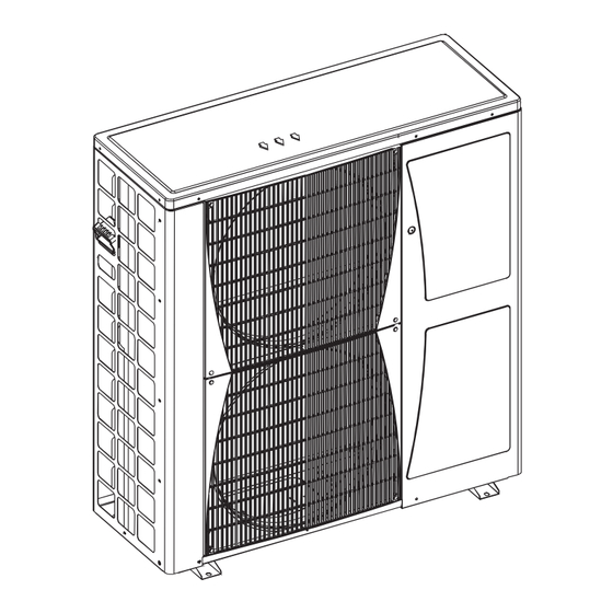
3. DIMENSIONAL DRAWINGS INDOOR UNIT (Evaporator) - right side connection Air Supply Electrical Box Access Panel Refrigeration Tubing Port Drain Port - G (OD) Return air spigots Control Unit Port Main Power Port DSD 40 RCA / GCD 40 RC DSD 40 RCA / GCD 40 RCX DSD 50 RCA / GCD 50 RCX DSD 60 RCA / GCD 60 RCX... - Page 5 OUTDOOR UNIT (Condenser) GCD 40 RC, GCD 40 RCX, GCD 50 RCX WALL 1. Wiring connections 300 MIN 2. Suction tube connector (flared) 3. Liquid tube connector (flared) 500 MIN FROM TOP 4. Service valves 5. Service taps 1000 MIN 6.
- Page 6 OUTDOOR UNIT (Condenser) GCD 60 RCX Figure 3. General dimensions of GCD 60 RCX outdoor unit WALL 300 MIN 500 MIN FROM TOP 1000 MIN WALL MINIMUM CLEARANCE mm Figure 3A. - Example of Installation...
-
Page 7: Indoor Unit Installation
4. INDOOR INSTALLATION 4.1 Indoor Unit Location (See Figure 4) The indoor unit is designed for installation on a false ceiling or other compartment, where there is no influence from outdoor conditions. While selecting the location, the following conditions must be assured: a) The location should assure free flow of the return air into the unit without interference. - Page 8 Where the unit must be installed in an attic space or outside, the following conditions must be assured: a) The unit must be protected from rain, heat and radiation by an additional layer of 1” thick thermal insulation. b) The return-air duct should be as short as possible, with a minimum dimension of 700x300 mm (or similar cross section) with full acoustical lining inside, and no more than two long-radius elbows.
-
Page 9: Floor Mounting
4.2 Floor Mounting - for DSD Series Only (See Figure 5) Place two layers of serrated 60x60 mm rubber pa at the four corners under the unit base. Insert a 1.5 mm thick sheet metal between the two rubber pads and between the bottom pad and the concrete surface. -
Page 10: Outdoor Unit Installation
b. Serrated Rubber Mounting In sites where the spring isolators assemblies cannot be installed, mount the unit as show in Figure 7. Insert four 3/8” studs in the ceiling according to the dimensions of the suspension angle frame mounted on the unit. Prepare 30x30 mm, 1.5 mm thick galvanized sheet metal for each stud and assemble according to Figure 6. -
Page 11: Installation Of Interconnecting Tubing Between Indoor And Outdoor Unit
6. INSTALLATION OF INTERCONNECTING TUBING BETWEEN INDOOR AND OUTDOOR UNITS 6.1 General (See Figure 9) The tubing between the indoor and outdoor units consist of two copper 1. To Outdoor Unit tubes and an electric cable routed 2. Interconnecting through a 60-mm wall opening. In Tubing addition, a drainage hose is installed 3. -
Page 12: Recomendation For Interconnecting Tubing Installation
Recommendation For Interconnection Tubing Installation Three possible versions are schematically illustrated: 1) The outdoor unit installed above the indoor unit (Figure 10) - such installation requires an oil trap in the suction line at the lowest point of the riser. The radius of the oil trap should be as short as possible (See Figure 11). -
Page 13: Setting In Operation
6.3 Setting in Operation WARNING This paragraph describes the necessary steps for setting the unit into operation; be sure to follow the instructions, to assure proper functioning of the air-conditioner. The outdoor unit is recharged with the correct amount of refrigerant. In extended runs, for additional refrigerant charge please refer to the outdoor unit name plate. - Page 14 CAUTION When performing the following steps, avoid any exposure to the service valve ports; remember that the system is under pressure g) Remove the valve caps from the three-way valves. Position both valves to “open” using an hexagonal wrench (See Figure 17). h) Replace valve caps of both three-way valves.
-
Page 15: Drain Installtion
Valve Protection Plug Insert Allen Wrench to open/close the Refrigerant Valve Valve Protection Cap Refrigerant Valve Service Port Cap Flare Nut Unit Back Side Copper Tube Figure 17. Three-way Refrigeration Valve 7. DRAIN LINE INSTALLATION a. It is recommended to prepare a drainage point with rigid PVC Ø... - Page 16 ELECTRICAL CONNECTION FOR 1PH DIGITAL SCROLL UNITS Since this air conditioner requires connection of high and low voltage between the units follow very carefully after electrical installation instructions bellow. Figure 19. Single Phase Units: Electrical Scheme power to outdoor. 1. Outdoor unit 7.
-
Page 17: Display Control Unit
ELECTRICAL CONNECTION FOR 3PH DIGITAL SCROLL UNITS Since this air conditioner requires connection of high and low voltage between the units follow very carefully after electrical installation instructions bellow. 6x1.5 ELECTRA COM+ COM+ COM- COM- Indoor Unit Outdoor Unit RS-485 Figure 20. -
Page 18: Interconnecting Cable
Interconnecting cable The electrical cable must be one integral piece, without any joints. When installing the cable under the floor, it must be protected and isolated from any possible contact with water. When the cable path runs inside the wall or an acoustic ceiling, it will be protected with a fire-retardant tubing system. In addition, In addition, the communication cable between the two units should be interconnected by using shielded cable. -
Page 19: Rcw-Remote Control
8.3.4 Display unit and master controller mounting 1. Main Control Board on Indoor Unit 2. Control Display Unit 3. Connection Wire *Option: Connecting the cable to control display terminal COLOR CHART Conn. Point Wire Color Gold Green Black Brown Purple Yellow Orange Figure 21. - Page 20 8.3.5 Remote Control Mounting a) Secure the control unit holder on the wall, using two screws with inserts (supplied with the unit) and peel the outside protection paper from the adhesive surface. b) Prior to operating the air conditioner, open the battery compartment cover and make sure that the red tab protecting the batteries has been removed.
-
Page 21: Final Tasks
FINAL TASKS 1. Return the stoppers and covers to their place and check that they are well closed. 2. Seal all the cracks and holes at the sides of the pipes and bores. 3. Attach the electrical wires and pipes to the wall with clamps. 4. - Page 22 TEL: (09) 820 0333 FAX: (09) 820 0332 Avondale, Auckland NZ NZ Tech Support Freecall TEL: 0800 180 094 www.airwell.com.au WITH A CONCERN FOR A CONSTANT IMPROVEMENT, OUR PRODUCTS CAN BE MODIFIED WITHOUT NOTICE. PHOTOS NON CONTRACTUAL. © Copyright 2004...
Need help?
Do you have a question about the DSD 40 RCA Series and is the answer not in the manual?
Questions and answers