
Related Manuals for Airwell YBD018 DCI


Summary of Contents for Airwell YBD018 DCI
- Page 1 YBD018 DCI Indoor Units Outdoor Units Delta 50 DCI LEX/HAD 50DCI DNG 50 DCI YBD018 DCI SLS 50 DCI CN 50 DCI PXD 50 DCI REFRIGERANT R410A HEAT PUMP DECEMBER– 2010 SM YBD018 1-A.1 GB Version: 1...
- Page 2 LIST OF EFFECTIVE PAGES LIST OF EFFECTIVE PAGES Note: Changes in the pages are indicated by a “Revision#” in the footer of each effected page (when none indicates no changes in the relevant page). All pages in the following list represent effected/ non effected pages divided by chapters.
-
Page 3: Table Of Contents
TABLE OF CONTENTS Table of Contents INTRODUCTION ....................1-1 PRODUCT DATA SHEET ..................2-1 RATING CONDITIONS ..................3-1 OUTLINE DIMENSIONS ..................4-1 PERFORMANCE DATA & PRESSURE CURVES ..........5-1 SOUND LEVEL CHARACTERISTICS (TO BE COMPLETED) ......6-1 ELECTRICAL DATA ....................7-1 WIRING DIAGRAMS .....................8-1 ELECTRICAL CONNECTIONS ................9-1 10. -
Page 4: Introduction
DC compressor sine wave torque control technology, this product are very suitable for most residential and comercial uses. The indoors can be Airwell wall mounted type and duct type and floor type DCI indoor units of 5.0kW cooling capaciy. - Page 5 INTRODUCTION Indoor Unit The indoor unit is wall mounted, and can be easily fitted to many types of residential and commercials applications. Feature Delta DCI LEX/HAD DCI DNG DCI SLS DCI CN DCI PXD DCI Display Ionizer Variable speed Variable speed Variable Variable Variable...
- Page 6 INTRODUCTION 1.10 Matching Table 1.10.1 R410A OUTDOOR INDOOR UNITS UNITS Delta 50 LEX/HAD 50 DNG 50 SLS 50 CN 50 DCI PXD 50 DCI YBD018 DCI √ √ √ √ √ √ SM YBD018 1-A.1 GB...
-
Page 7: Product Data Sheet
PRODUCT DATA SHEET PRODUCT DATA SHEET Delta 50 DCI / YBD018 Model Indoor Unit DELTA 50 DCI Model Outdoor Unit YBD 018 Installation Method of Pipe Flared Characteristics Cooling Heating Units 17060(5120-19790) 18080(4440-22520) Btu/hr Capacity (4) 5.0(1.5-5.8) 5.3(1.3-6.6) Power input (4) 1.47(0.4-2.0) 1.47(0.36-2.1) EER (Cooling) or COP(Heating) (4) - Page 8 PRODUCT DATA SHEET LEX 50 DCI / YBD018 Model Indoor Unit LEX 50 DCI Model Outdoor Unit YBD 018 Installation Method of Pipe Flared Characteristics Cooling Heating Units Btu/hr 17060(5120-20470) 19110(4440-23200) Capacity (4) 5.0(1.5-6.0) 5.6(1.3-6.8) Power input (4) 1.37(0.4-2.0) 1.46(0.35-2.0) EER (Cooling) or COP(Heating) (4) 3.65 3.84...
- Page 9 PRODUCT DATA SHEET HAD 50 DCI / YBD018 Model Indoor Unit HAD 50 DCI Model Outdoor Unit YBD 018 Installation Method of Pipe Flared Characteristics Cooling Heating Units Btu/hr 17060(5120-20470) 19110(4440-23200) Capacity (4) 5.0(1.5-6.0) 5.6(1.3-6.8) Power input (4) 1.37(0.4-2.0) 1.46(0.35-2.0) EER (Cooling) or COP(Heating) (4) 3.65 3.84...
- Page 10 PRODUCT DATA SHEET CN 50 DCI / YBD018 Model Indoor Unit CN 50 DCI Model Outdoor Unit YBD 018 Installation Method of Pipe Flared Characteristics Cooling Heating Units Btu/hr 17060(5120-19790) 19110(4440-23200) Capacity (4) 5.0(1.5-5.8) 5.6(1.3-6.8) Power input (4) 1.51(0.4-2.0) 1.53(0.34-2.0) EER (Cooling) or COP(Heating) (4) 3.31 3.66...
- Page 11 PRODUCT DATA SHEET PXD 50 DCI / YBD018 Model Indoor Unit PXD 50 DCI Model Outdoor Unit YBD 018 Installation Method of Pipe Flared Characteristics Cooling Heating Units 17060(5120-19790) 19110(4440-22180) Btu/hr Capacity (4) 5.0(1.5-5.8) 5.6(1.3-6.5) Power input (4) 1.51(0.4-2.0) 1.59(0.36-2.0) EER (Cooling) or COP(Heating) (4) 3.31 3.52...
- Page 12 PRODUCT DATA SHEET SLS 50 DCI / YBD018 Model Indoor Unit SLS 50 DCI Model Outdoor Unit YBD 018 Installation Method of Pipe Ducted Characteristics Units Cooling Heating Btu/hr 17060(5120-19790) 19110(4440-23200) Capacity (4) 5.0(1.5-5.8) 5.6(1.3-6.8) Power input (4) 1.51(0.4-2.0) 1.55(0.34-2.0) EER (Cooling) or COP(Heating) (4) 3.31 3.61...
-
Page 13: Rating Conditions
RATING CONDITIONS RATING CONDITIONS Standard conditions in accordance with ISO 5151 and ISO 13253 (for ducted units) and EN 14511. Cooling: Indoor: C DB 19 C WB Outdoor: 35 C DB Heating: Indoor: C DB Outdoor: 7 C DB 6 C WB Operating Limits Indoor... -
Page 14: Outline Dimensions
OUTLINE DIMENSIONS OUTLINE DIMENSIONS Indoor Unit: DELTA 50 DCI Indoor Unit: LEX 50 DCI 1060 Indoor Unit: HAD 50 DCI SM YBD018 1-A.1 GB... - Page 15 OUTLINE DIMENSIONS Indoor Unit: PXD 50 DCI Indoor Unit: CN 50 DCI 625 or 725 SM YBD018 1-A.1 GB...
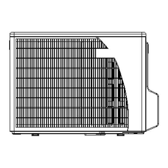
- Page 16 OUTLINE DIMENSIONS Outdoor Unit: YBD018 SM YBD018 1-A.1 GB...
-
Page 17: Performance Data & Pressure Curves
PERFORMANCE DATA & PRESSURE CURVES PERFORMANCE DATA & PRESSURE CURVES Delta 50 DCI 5.1.1 Cooling Capacity (kW) Entering Air DB Data Entering Air WB/DB ID Coil( OD Coil( 15/21 17/24 19/27 21/29 23/32 5.10 5.40 5.65 5.90 6.10 3.32 3.52 3.71 3.62 3.68... - Page 18 PERFORMANCE DATA & PRESSURE CURVES 5.1.3 Heating ENTERING AIR DB ID COIL( ENTERING WB OD COIL( 2.78 1.18 2.68 1.25 2.57 1.32 2.99 1.21 2.89 1.27 2.78 1.34 3.18 1.22 3.07 1.29 2.97 1.37 3.87 1.28 3.71 1.36 3.55 1.44 5.46 1.37 5.30...
- Page 19 PERFORMANCE DATA & PRESSURE CURVES LEX 50 DCI 5.2.1 Cooling Capacity (kW) Entering Air DB Data Entering Air WB/DB ID Coil( OD Coil( 15/21 17/24 19/27 21/29 23/32 5.10 5.40 5.65 5.90 6.10 3.69 3.92 4.13 4.03 4.10 0.97 0.97 0.98 0.98 0.98...
- Page 20 PERFORMANCE DATA & PRESSURE CURVES 5.2.3 Heating ENTERING AIR DB ID COIL( ENTERING WB OD COIL( 2.94 1.17 2.83 1.24 2.72 1.31 3.16 1.20 3.05 1.26 2.94 1.33 3.36 1.21 3.25 1.28 3.14 1.36 4.09 1.27 3.92 1.35 3.75 1.43 5.77 1.37 5.60...
- Page 21 PERFORMANCE DATA & PRESSURE CURVES CN 50 DCI 5.3.1 Cooling Capacity (kW) Entering Air DB Data Entering Air WB/DB ID Coil( OD Coil( 15/21 17/24 19/27 21/29 23/32 5.10 5.40 5.65 5.90 6.10 3.35 3.55 3.74 3.65 3.71 1.07 1.07 1.08 1.08 1.08...
- Page 22 PERFORMANCE DATA & PRESSURE CURVES 5.3.3 Heating ENTERING AIR DB ID COIL( ENTERING WB OD COIL( 2.94 1.22 2.83 1.30 2.72 1.37 3.16 1.25 3.05 1.32 2.94 1.40 3.36 1.27 3.25 1.35 3.14 1.42 4.09 1.33 3.92 1.42 3.75 1.50 5.77 1.43 5.60...
- Page 23 PERFORMANCE DATA & PRESSURE CURVES PXD 50 DCI 5.4.1 Cooling Capacity (kW) Entering Air DB Data Entering Air WB/DB ID Coil( OD Coil( 15/21 17/24 19/27 21/29 23/32 5.10 5.40 5.65 5.90 6.10 3.69 3.92 4.13 4.03 4.10 1.07 1.07 1.08 1.08 1.08...
- Page 24 PERFORMANCE DATA & PRESSURE CURVES 5.4.3 Heating ENTERING AIR DB ID COIL( ENTERING WB OD COIL( 2.94 1.27 2.83 1.35 2.72 1.42 3.16 1.30 3.05 1.38 2.94 1.45 3.36 1.32 3.25 1.40 3.14 1.48 4.09 1.38 3.92 1.47 3.75 1.56 5.77 1.49 5.60...
- Page 25 PERFORMANCE DATA & PRESSURE CURVES DNG 50 DCI 5.5.1 Cooling Capacity (kW) Entering Air DB Data Entering Air WB/DB ID Coil( OD Coil( 15/21 17/24 19/27 21/29 23/32 5.10 5.40 5.65 5.90 6.10 4.18 4.43 4.67 4.56 4.64 1.10 1.10 1.10 1.11 1.11...
- Page 26 PERFORMANCE DATA & PRESSURE CURVES 5.5.3 Heating ENTERING AIR DB ID COIL( ENTERING WB OD COIL( 3.15 1.29 3.03 1.37 2.91 1.44 3.39 1.32 3.27 1.39 3.15 1.47 3.60 1.34 3.48 1.42 3.36 1.50 4.38 1.40 4.20 1.49 4.02 1.58 6.18 1.51 5.79...
- Page 27 PERFORMANCE DATA & PRESSURE CURVES LSN 50 DCI 5.6.1 Cooling Capacity (kW) Entering Air DB Data Entering Air WB/DB ID Coil( OD Coil( 15/21 17/24 19/27 21/29 23/32 5.10 5.40 5.65 5.90 6.10 3.42 3.63 3.82 3.74 3.80 1.07 1.07 1.08 1.08 1.08...
- Page 28 PERFORMANCE DATA & PRESSURE CURVES 5.6.3 Heating ENTERING AIR DB ID COIL( ENTERING WB OD COIL( 2.94 1.24 2.83 1.32 2.72 1.39 3.16 1.27 3.05 1.34 2.94 1.41 3.36 1.29 3.25 1.36 3.14 1.44 4.09 1.35 3.92 1.43 3.75 1.52 5.77 1.45 5.60...
-
Page 29: Sound Level Characteristics (To Be Completed)
SOUND LEVEL CHARACTERISTICS SOUND LEVEL CHARACTERISTICS Sound Pressure Level Figure 1 Soud Pressure Level Spectrum (Measured as Figure 1) ****** ****** FAN SPEED LINE SM YBD018 1-A.1 GB... -
Page 30: Electrical Data
ELECTRICAL DATA ELECTRICAL DATA YBD018 MODEL YBD018 To indoor Power Supply 1PH-230V-50/60Hz Max Current, A Circuit Breaker,A Power Supply Wiring No. X Cross Section mm 3x2.5 mm Interconnecting Cable Model No. X Cross Section mm 4x2.5 mm NOTE Power wiring cord should comply with local laws and electrical regulations requirements. SM YBD018 1-A.1 GB... -
Page 31: Wiring Diagrams
WIRING DIAGRAMS WIRING DIAGRAMS Outdoor Unit: SM YBD018 1-A.1 GB... -
Page 32: Electrical Connections
ELECTRICAL CONNECTIONS ELECTRICAL CONNECTIONS Wiring Diagram between Indoor Unit and Outdoor Unit SM YBD018 1-A.1 GB... -
Page 33: Refrigeration Diagrams
REFRIGERATION DIAGRAMS REFRIGERATION DIAGRAMS 10.1 Cooling and Dry Mode 10.2 Heating Mode SM YBD018 1-A.1 GB 10-1... -
Page 34: Tubing Connections
TUBING CONNECTIONS TUBING CONNECTIONS TUBE (Inch) ¼” ⅜” ½” ⅝” ¾” TORQUE (Nm) Flare Nuts 15-18 40-45 60-65 70-75 80-85 Valve Cap 13-20 13-20 18-25 18-25 40-50 Service Port Cap 11-13 11-13 11-13 11-13 11-13 Valve Protection Cap-end Refrigerant Valve Port (use Allen wrench to open/close) Valve Protection Cap Refrigerant Valve Service Port Cap... -
Page 35: Control System
CONTROL SYSTEM CONTROL SYSTEM 12.1 Electronic Control 12.1.1 General Functions and Operating Rules (for single split models) The DCI software is fully parametric. All the model dependent parameters are shown in Blue color and with Italic style [parameter]. The parameters values are given in the last section of this control logic chapter of the service manual. - Page 36 CONTROL SYSTEM Definitions Cool Heat MinFreqC MinFreqH MinFreq MaxFreq MaxFreqC MaxFreqH LoadDeadZone LoadDeadZoneC LoadDeadZoneH During running time (unlike starting) Compressor can operate only in its allowed frequency range. The lower allowed frequency is extracted from the following: Mode MinFreq MinFreqA MinFreq MinFreqA Cool...
- Page 37 CONTROL SYSTEM 12.1.1.1 Frequency Changes Control Frequency change rate is 1 Hz/sec. 12.1.1.1 Compressor Starting Control Frequency Step 3 Step 2 Step 1 Minute Time Minute Min 10 Minutes 12.1.1.1 Minimum On and Off Time 3 minutes. 12.1.4 Indoor Fan Control 10 Indoor fan speeds are determined for each model.
- Page 38 CONTROL SYSTEM 12.1.7 Outdoor Fan Control 12.1.1.1 The following are the speeds types(General Rules): Speed Controlled by High Relay Triac (27% to 85% effective voltage) 12.1.1.1 OFAN Speed Type AC Motor (OFANType=2) Triac Relay Effective voltage Metric R.M.S (V%) ‘A’: Cool OFMinPercentC - Lower Speed...
-
Page 39: Fan Mode
CONTROL SYSTEM Cooling heating Default Selection Default Selection Relay On; Triac Off Relay On; Triac Off Relay Off; Triac On Relay Off; Triac On (27-7) (20+4) (15+7) (20+4) Minimum Maximum Condensing pressure Evaporating pressure The Triac and the Relay can never be activated at the same time 12.1.8 EEV (electronic Expansion valve) Control EEV opening is defined as EEV = EEV... -
Page 40: Cool Mode
CONTROL SYSTEM 12.3 Cool Mode NLOAD is calculated according to the difference between actual room temperature and user set point temperature by PI control. In high/ medium/ low indoor fan user setting, unit will operate fan in selected speed. In AutoFan user setting, fan speed will be adjusted automatically according to the calculated NLOAD. - Page 41 CONTROL SYSTEM 12.7 Protections There are 5 protection codes. Normal (Norm) – unit operate normally. Stop Rise (SR) – compressor frequency can not be raised but does not have to be decreased. HzDown1 (D1) – Compressor frequency is reduced by Down1 Hz/min.
- Page 42 CONTROL SYSTEM Stop-Compresor CTTOH4 CTTOH3 CTTOH2 CTTOH1 Normal Control Status Compressor Temperature Else Increases Norm Stop Compressor 12.7.4 Outdoor Coil Overheating Protection -OMT <-1 >1 HPC5 HPC4 < HPC5 HPC3 < HPC4 HPC2 < HPC3 HPC1 OMT < HPC2 Norm Norm Norm Norm...
- Page 43 CONTROL SYSTEM 12.7.6 Heat Sink Over Heating Protection A new control status will be set according to the following graph every one-minute or whenever when going up by the rows. is the current reading of HST and HST is the last reading of HST. -HST <-1 >1...
- Page 44 CONTROL SYSTEM Case 1: OCT<–DST AND TLD > DI Case 2: OCT<-4 AND TLD>100 minutes Case 3: OCT is Invalid AND TLD > DI Case 4: Unit is just switched to STBY AND OCT<-DST Case 5: compressor is stopped during heating operation, OCT<-DST AND TLD>DI, OCT –...
- Page 45 CONTROL SYSTEM 12.7.1.1 Exiting Deicing OCT > OCTExitDeicer or Deicer current time is over MaxDeicerTim minutes. 12.7.9 Condensate Water Over Flow Protection Outdoor unit receives “overflow’ signal from the indoor side. Each of the pins P1, P2, P3 can have two options: 1 –...
- Page 46 CONTROL SYSTEM 12.7.1.1 1 Level Logic (used in all models except for floor/ceiling models) Level Don’t Normal care Don’t Overflow care Overflow when Overflow when unit is ON unit is OFF Overflow Water Level Normal OPER BLINK NLOAD is NLOAD forced to 0 PUMP 8 min...
- Page 47 CONTROL SYSTEM 12.9 Operating the Unit from the Mode Button Forced operation allows to start, stop and operate in Cooling or Heating, in pre-set temperature according to the following table: Forced operation Mode Pre-set Temperature Cooling Heating 12.10 Indoor Unit Controllers and Indicators For Delta IDU The following is schematic drawing for the display: Timer...
- Page 48 CONTROL SYSTEM Blinks for 3 seconds when the system is switched to Cool Mode by using the Mode/Reset Switch on the unit. TIMER INDICATOR Lights up during Timer and Sleep operation. Lights up when Air Filter needs to be cleaned. FILTER INDICATOR As long as the filter Led is off, the Mode/Reset button functions as Mode/Reset Button...
- Page 49 CONTROL SYSTEM Lights up when Air Filter needs to be cleaned. FILTER INDICATOR COOLING INDICATOR Lights up when system is switched to Cool Mode by using the Mode Switch on the unit. HEATING INDICATOR Lights up when system is switched Heat Mode by using the Mode Switch on the unit.
- Page 50 CONTROL SYSTEM A -- Lights up when IFAN setting is Auto. Each one of the seven indicators indicates the following SPT: 18, TEMP. SETTING 20, 22, 24, 26, 28, 30 [ c]. The odd number temperatures are INDICATORS indicated by turning on the two adjacent indicators. Press this button to change the speed of the IFAN.
- Page 51 CONTROL SYSTEM 12.11 Outdoor Unit Controllers and Indicators 12.11.1 The user display uses three 7 segments. 12.11.1.1 The user interface concept is Tree menus. 12.11.1.1 The navigation through the menu can be performed by either the key pad or RC8 remote controller (through infra red receiver). RC8 sketch: Command Function...
- Page 52 CONTROL SYSTEM 3. For any remote controller command, the most right ‘dot’ will blink for 1 second in order to acknowledge the command is received. 12.11.1.1 Active selection or status will be indicated by blinking the display. 12.11.2 Keys functionality o Scrolling will be done whenever the button is pressed.
- Page 53 CONTROL SYSTEM 6. When Technician test cool or heat menus are selected (operative), it will be blinking constantly until, this menu is escaped. 7. When the installation test begins, the system will show up count down based (refer to the installation test sect.
- Page 54 CONTROL SYSTEM Deicing Compressor Over Heating Compressor Over Current No OFAN Feedback OFAN IPM fault / OFAN IPM Driver Pin Compressor Lock Bad Communication Missing ODU configuration Undefined ODU Model Outdoor/Indoor Coil Overheating Operation conditions are exceeded 12.12 Jumper Settings 12.12.1 Indoor Unit Controller 12.12.1.1 Hardware Jumpers...
- Page 55 CONTROL SYSTEM Delta 50 NPXD Reserved Note: 1. Delta 50 is used for Delta Product. This family occupies family No. 10 on the communication level. Model selection Jumper – J7, J8 Model 12.12.1.1 Software Jumpers For Delta DCI Property EEPROM DATA (J1) Use ROM* Use EEPROM ‘Thermostatic Stop- Heat’...
- Page 56 CONTROL SYSTEM Enable Test Mode (J5) Deactivated Activated* * Default values (used in the ROM) Default SW jumpers according to the family (used in the ROM) Property ‘Thermostatic Stop- Heat’ (J2) ‘Heat to STBY’ (J3) Water Level Protection (J4) J1 – EEPROM/ROM setting When J1 is 1, IDU will use model/family/general parameters from EEPROM.
-
Page 57: Test Mode
CONTROL SYSTEM J1 – EEPROM/ROM setting When J1 is 1, ODU will use model/general parameters from EEPROM. If EEPROM is invalid, ODU will ignore J1 and use/copy the ROM pointed by the selected jumpers (will also set an according fault). 12.13 Test Mode 12.13.1... - Page 58 CONTROL SYSTEM 1. For the protections, except for water level protections, only the “Stop-Compressor” status will be operative. For other protection statuses, the system will behave as in normal one. 2. The vertical louver should be Test_Mode_ Angle ,it should be vertical.Louvers angles will be set according to the IDU family and Mode: 12-24 SM YBD018 1-A.1 GB...
-
Page 59: Troubleshooting
TROUBLESHOOTING TROUBLESHOOTING 13.1 ELECTRICAL & CONTROL TROUBLESHOOTING WARNING!!! When Power Up – the whole outdoor unit controller, including the wiring, is under HIGH VOLTAGE!!! Never open the Outdoor unit before turning off the Power!!! When turned off, the system is still charged (400V)!!! It takes about 4 Min. - Page 60 TROUBLESHOOTING PROBABLE SYMPTOM CORRECTIVE ACTION CAUSE Unit works in wrong Electronics or Check RV power connections, if OK, mode (cool instead of power connection Check RV operation with direct 230VAC heat or heat instead of to RV power supply, if OK, cool) Replace outdoor controller.
- Page 61 TROUBLESHOOTING In diagnostics mode, system fault / status will be indicated by blinking of Filter & Timer LEDs. The coding method will be as follows: Filter LED will blink 5 times in 5 seconds, and then will be shut off for the next 5 seconds. Timer LED will blink during the same 5 seconds according to the following Indoor / Outdoor unit tables: Note: 0 –...
- Page 62 TROUBLESHOOTING Fault Probable Cause Corrective Action No problem. System is using Using EEPROM data EEPRRRROM parameters 13.1.3.3 Outdoor unit Diagnostics Problem OCT is shorted/disconnected CTT is shorted/disconnected HST is shorted/disconnected OAT is shorted/disconnected OMT is shorted/disconnected RGT is shorted/disconnected RLT is shorted/disconnected Reserved Low pressure protection Reserved...
- Page 63 TROUBLESHOOTING Fault Probable Cause Corrective Action Check outdoor unit power DC under/over Voltage Electronics HW problem supply voltage Check outdoor unit power AC under Voltage supply voltage Indoor and Outdoor Indoor / Outdoor unit controllers are with Replace Indoor controller Communication mismatch different versions Communication or grounding...
- Page 64 TROUBLESHOOTING 13.2.5 Checking the Reverse Valve (RV). Running in heating mode, check the voltage between two pins of reverse valve connector, normal voltage is 220VAC. 13.3 Precaution, Advise and Notice Items 13.3.1 High voltage in Outdoor unit controller. Whole controller, including the wires that are connected to the Outdoor unit controller may have the potential hazard voltage when power is on.
-
Page 65: Exploded Views And Spare Parts Lists
EXPLODED VIEWS AND SPARE PARTS LISTS EXPLODED VIEWS AND SPARE PARTS LISTS 14.1 Outdoor Unit: YBD018 SM YBD018 1-A.1 GB 14-1... - Page 66 EXPLODED VIEWS AND SPARE PARTS LISTS 14.2 Outdoor Unit: YBD018 Description Qua. 433218 Front Panel A 4526340 Air inlet ring-420 433223 Painting Insulation Plate 464250118 Fireproofing plate/ONG3 DIC 4519251 Axial Fan OD=400 466100034R Metal Motor 4527203 Motor Support 464600094 Base Painting Assy. 464160024 Partition Plate 467550005R...
- Page 67 APPENDIX A APPENDIX A INSTALLATION AND OPERATION MANUAL ► REMOTE CONTROL RC7 ► INSTALLATION AND OPERATION MANUAL YIF018 DCI SERIES 15-1 SM YBD018 1-A.1 GB...
Need help?
Do you have a question about the YBD018 DCI and is the answer not in the manual?
Questions and answers