Table of Contents
Advertisement
Quick Links
Advertisement
Table of Contents

Related Manuals for AES BP700R


Summary of Contents for AES BP700R
- Page 1 01284 658770 sales@automatedenvironmentalsystems.co.uk Commercial Swimming Pool Heat Pump - Installation and Service Manual - (Inverter Type) BP700R Automated Environmental Systems Ltd. Unit B, Anglian Lane, Bury St. Edmunds, Suffolk, IP32 6SR...
-
Page 3: Table Of Contents
General information ……………………………………………………………………………………………………………………………3 Items inside product box …………………………………………………………………………………………………………………….3 ……………………………………………………………………………………………………………………..4 SAFETY PRECAUTIONS Warning ………………………………………………………………………………………………………………………………………………4 Caution………………………………………………………………………………………………………………………………………………..5 OVERVIEW OF THE UNIT……………………………………………………………………………………………………………………..7 External view: BP700R …………………………………………………………………………………………………………………………………… 7 Exploded view: BP700R …………………………………………………………………………………………………………………………………….8 ……………………………………………………………………………………………………………………….9 OPERATING THE UNIT Features and function…………..……………………………………………………………………………………………………………..9 USER INTERFACE …………..……………………………………………………….……………………………………………………….…10 …………………………………………………………………………………………………………………. 13 PARAMETER CHECKIN Error Code …………………………………………………….…….…………………..………………………………………………………..14... -
Page 4: Introduction
INTRODUCTION This manual includes the necessary information about the unit. Please read this manual carefully before you install, operate and maintain the unit. General information The heat pump water heater is one of the most economical systems to heat the water for family domestic use. -
Page 5: Safety Precautions
SAFETY PRECAUTIONS To prevent injury to the user, other people, or property damage, the following instructions must be followed. Incorrect operation due to ignoring of instructions may cause harm or damage. Install the unit only when it complies with local regulations, by-laws and standards. Check the main voltage and frequency. -
Page 6: Caution
Never use an extension cable to connect the unit to the electric power supply. If there is no suitable, earthed wall socket available, have one installed by a recognized electrician. Do not move/repair the unit yourself. Improper movement or repair on the unit could lead to water leakage, electrical shock, injury or fire. Have any repairs and/or maintenance only carried out by a recognized service engineer. - Page 7 Be cautious when unpacking and installing the product. Sharp edges could cause injury. Especially watch the edges and the fins on the heat exchanger of the product. Always check for gas (refrigerant) leakage after installation or repair of product. Low refrigerant levels may cause failure of the product. Keep level even when installing the product.
-
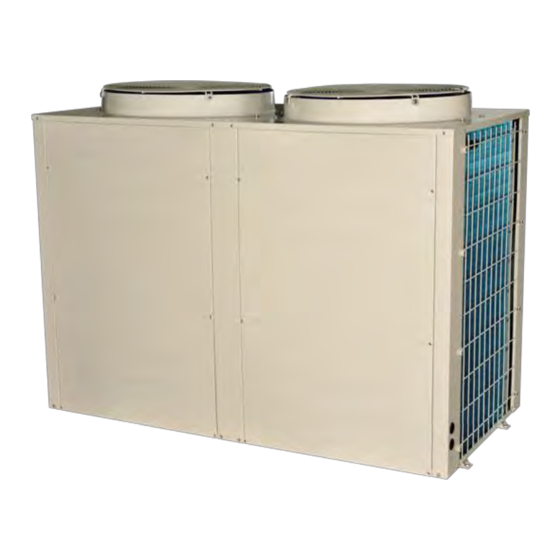
Page 8: Overview Of The Unit
OVERVIEW OF THE UNIT External view: BP700R... -
Page 9: Exploded View
Exploded view: BP700R Item Description Item Description Top grill Bottom plate assembly Top cover Front right panel Rear middle pillar Front middle pillar Rear grill Front left panel Rear right pillar Titanium heat exchanger Right grill EEV assembly Front right pillar... -
Page 10: Operating The Unit
OPERATING THE UNIT Operating the unit comes down to operating the digital controller. NEVER LET THE DIGITAL CONTROLLER GET WET. THIS MAY CAUSE AN ELECTRIC SHOCK OR FIRE. NEVER PRESS THE BUTTONS OF THE DIGITAL CONTROLLER WITH A HARD, POINTED OBJECT. THIS MAY DAMAGE THE DIGITAL CONTROLLER. -
Page 11: User Interface
USER INTERFACE ON/OFF DOWN Mode Setup Outlet water temp Temperature(℉/℃) Lock Screen Alarm Display Time (MIN) WIFI Indicator Temperature (℉/℃) Cooling mode Heating Mode IN-- Inlet water temp , SET- Setting parameters Silent mode Smart mode Boost mode Clock ON-- Timer ON , OFF-- Timer OFF -- Timer number Icon Introduction:... - Page 12 Key operation instructions 1. “ ” ON/OFF Short press “ ”as Exit Key to return to main interface, press and hold the “ ” key for 3 seconds to turn the unit ON or OFF. 2. “ ” Mode When the unit is ON, long press “ ”for 3 seconds to switch different working modes: Heating mode and Cooling mode.
- Page 13 Timer settings: Press and hold the “ ”key for 3 seconds to enter Timer setting: "Timer On 1" "Hour" flashes. With “ ”、“ ”, you can set the hour; Press “ ”key again to switch to the Timer "minute", and use the “ ”、“...
-
Page 14: Parameter Checkin
PARAMETER CHECKING Unit running status table On the main operation interface, press and hold“ ” key for 3 seconds to enter Unit Running Status Parameter Query, and use the “ ”、“ ” keys to navigate different parameters, press the“ ”key to exit. ◎... -
Page 15: Error Code
Error Code Error codes Fault description Marks Er 03 Water flow fault Er 04 Antifreeze in winter Er 05 High pressure fault Er 06 Low pressure fault Er 09 Communication failure Er 10 Communication failure of inverter module (Alarm activated when communication between PCB and IPM board is disconnected.) Er 12 High exhaust gas temperature protection... -
Page 16: Wiring Diagram
WIRING DIAGRAM of BP700R (Please refer to the attached wiring diagram on the unit.) -
Page 17: Installation Of The Unit
INSTALLATION OF THE UNIT Installation guidelines Precautions for selecting the location MAKE SURE TO PROVIDE FOR ADEQUATE MEASURES IN ORDER TO PREVENT THAT THE OUTDOOR UNIT WILL BE USED AS A SHELTER FOR SMALL ANIMALS. SMALL ANIMALS MAKING CONTACT WITH ELECTRICAL PARTS CAN CAUSE MALFUNCTIONS, SMOKE OR FIRE. -
Page 18: Installation Space
Installation space AIR FLOW OUT AIR FLOW IN Mounting the unit When installing the outdoor unit, please refer to “Installation guidelines” to select an appropriate location. 1. Check the strength and level of the installation ground so that the unit will not cause any operating vibration or noise after installation. -
Page 19: Connecting The Water Circuit
Drain taps must be provided at all low points of the system to permit complete drainage of the circuit during maintenance. Air vents must be provided at all high points of the system. The vents should be located at ... -
Page 20: Charging Water
Incomplete earth may cause electrical shock. Be sure to install an earth leakage protector. Failure to do so may cause electrical shock. Wiring overview The table below gives a wiring overview of the required field wiring. Model BP700R Power supply ≥ 4.0 mm ×5... -
Page 21: Pre-Operation Checks
Pre-operation checks Checks before initial start-up SWITCH OFF THE POWER SUPPLY BEFORE MAKING ANY CONNECTIONS. After the installation of the unit, check the following before switching on the circuit breaker: 1. Field wiring Make sure that the field wiring between the local supply panel and domestic hot water tank has been carried out according to the instructions, according to the wiring diagrams and according to European and national regulations. -
Page 22: Maintenance
9. Water flow switch should be installed for the place where there is no constant sufficient water flow (Field supply). 10. Stop valves Make sure that the stop valves are correctly installed and fully open. OPERATING THE SYSTEM WITH CLOSED VALVES WILL DAMAGE THE PUMP! MAINTENANCE In order to ensure optimal availability of the unit, a number of checks and inspections on the unit and the field wiring have to be carried out at regular intervals. -
Page 23: Plumbing Connections
PLUMBING CONNECTIONS The heat pump should be connected to a filtration circuit through a by-pass which consists of 3 valves. It is imperative that the by-pass is placed after the pump and the filter. These valves allow to regulate the water flow which passes through the heat pump and to isolate the heat pump completely for any maintenance work, without cutting the filtration flow. - Page 24 MAINTENANCE To protect the paintwork, avoid leaning or putting objects on the shell. External Heat Pump parts can be wiped with a damp cloth and domestic cleaner. (Warning: Never use cleaning agents containing sand, soda, acid or chloride as these can damage the surfaces.) To prevent blockages in the titanium heat exchanger, ensure that the system incorporates a water and filter treatment facility.
-
Page 25: Troubleshooting
sharp objects for cleaning. Under extreme weather conditions (e.g. snow drifts), ice may form on the air intake and exhaust air outlet grids. If this happens, the ice must be removed in the vicinity of the air intake and exhaust air outlet grids to ensure that the minimum air flow rate is maintained. Winter Shutdown. - Page 26 The Heat pump will not run. Please check: There is a supply voltage (tripped fuse, power failure). The switch on the wired controller is switched on, and whether the correct set point temperature has been set. The set temperature level cannot be reached. Please check whether: The permissible operating conditions for the heat pump have been adhered to (air ...
-
Page 27: Environmental Iiformation
ENVIRONMENTAL INFORMATION This equipment contains fluorinated greenhouse gases covered by the Kyoto Protocol. It should only be serviced or dismantled by professional trained engineers. This equipment contains R32 refrigerant in the amount as stated in the specification. Do not vent R32 into the atmosphere: R32, is a fluorinated greenhouse gas with a Global Warming Potential (GWP) = 675. -
Page 28: Wifi / App Application
WIFI / APP APPLICATION 1. Install APP. Please search in the app store or scan the QR code below to install the APP "Smart life - Smart Living" 1.Seach "Smart life - Smart Living" 2.Recognize this trademark 3.install. 2. Startup software. After the installation is complete, click on the desktop icon "Smart Life"... - Page 29 2.1 After installation completed, please open the APP to do Register Step below.
- Page 31 2.2 Please log in with your Register ID.
- Page 32 3. Add device 3.1 Please open the controller to operate WIFI Paring. Press and hold the keys simultaneously for 3 seconds to enter the “+”and“ ” "Default Mode" distribution network. When entering, the icon flashes quickly; “ ” 2.Flash. 1.Press "+" and"M"for 3s.
- Page 33 3.2 Click “Add Device” and select “Electrical” and“Switch(Wi-Fi)”to connect WIFI.
- Page 35 3.4 Input the WIFI ID and Password to search for devices.
- Page 36 3.5 Add and connect to the device.
- Page 37 4. Device Management and Control. Detail settings Set Temperature: Slide on the screen to adjust Running mode Schedule & temperature scale Mode setting settings Switch...
Need help?
Do you have a question about the BP700R and is the answer not in the manual?
Questions and answers