Table of Contents
Advertisement
7024515
Hydro-Pro Heat pump ABS 230V Inverter type Inverter 07 horizontal,R32
7024516
Hydro-Pro Heat pump ABS 230V Inverter type Inverter 11 horizontal,R32
7024517
Hydro-Pro Heat pump ABS 230V Inverter type Inverter 14 horizontal,R32
7024518
Hydro-Pro Heat pump ABS 230V Inverter type Inverter 16 horizontal,R32
7024519
Hydro-Pro Heat pump ABS 230V Inverter type Inverter 19 horizontal,R32
7024520
Hydro-Pro Heat pump ABS 230V Inverter type Inverter 24 horizontal,R32
7024521
Hydro-Pro Heat pump ABS 400V Inverter type Inverter 24T horizontal,R410A
7024522
Hydro-Pro Heat pump ABS 230V Inverter type Inverter 29 horizontal,R32
7024523
Hydro-Pro Heat pump ABS 400V Inverter type Inverter 29T horizontal,R410A
INVERBOOST+ Tech
Swimming Pool Heat Pump
User and Service manual
Advertisement
Table of Contents

Related Manuals for AES Hydro-Pro Inverter 11


Summary of Contents for AES Hydro-Pro Inverter 11
- Page 1 7024515 Hydro-Pro Heat pump ABS 230V Inverter type Inverter 07 horizontal,R32 7024516 Hydro-Pro Heat pump ABS 230V Inverter type Inverter 11 horizontal,R32 7024517 Hydro-Pro Heat pump ABS 230V Inverter type Inverter 14 horizontal,R32 7024518 Hydro-Pro Heat pump ABS 230V Inverter type Inverter 16 horizontal,R32 7024519 Hydro-Pro Heat pump ABS 230V Inverter type Inverter 19 horizontal,R32 7024520...
- Page 2 Automated Environmental Systems Ltd. 1 Wimbledon Avenue, Brandon, IP27 0NZ 01842 819130 sales@automatedenvironmentalsystems.co.uk Buy online www.automatedenvironmentalsystems.co.uk...
- Page 3 Regulation (EU) n° 517/2014 of 16/04/14 on fluorinated greenhouse gases and repealing Regulation (EC) n° 842/2006 Leak checks 1. Operators of equipment that contains fluorinated greenhouses gases in quantities of 5 tons of CO , equivalent more and not contained in foams shall ensure that the equipment is checked for leaks. For equipment that contains fluorinated greenhouse gases in quantities of 5 tons of equivalent or more, but of less than 50 tons of...
- Page 4 hydro-pro inverter Swimming Pool Heat Pump User and Service manual INDEX 1. Specifications 2. Dimension 3. Installation and connection 4. Accessories 5. Electrical Wiring 6. Display Controller Operation 7. Troubleshooting 8. Exploded Diagram 9. Maintenance 10. Warranty and returns Thank you for using hydro-pro inverter swimming pool heat pump for your pool heating, it will heat your pool water and keep the constant temperature when the air ambient temperature is at -12 to 43℃...
-
Page 5: Specifications
1. Specifications 1.1 Technical data hydro-pro inverter pool heat pumps Model Inverter 07 Inverter 11 Inverter 14 Inverter 16 Item No. 7024515 7024516 7024517 7024518 * Performance at Air 28℃, Water 28℃, Humidity 80% Heating capacity 7-2.2 11-2.9 14-3.2 16-3.8 Power consumption 1.25-0.17 1.77-0.22... - Page 6 1.2 Technical data hydro-pro inverter pool heat pumps Model Inverter 19 Inverter 24 Inverter 24T Inverter 29 Inverter 29T Item No. 7024519 7024520 7024521 7024522 7024523 * Performance at Air 28℃, Water 28℃, Humidity 80% Heating capacity 19-4.7 25.5-5.9 25.5-5.9 30-6.8 30-6.8 Power consumption...
-
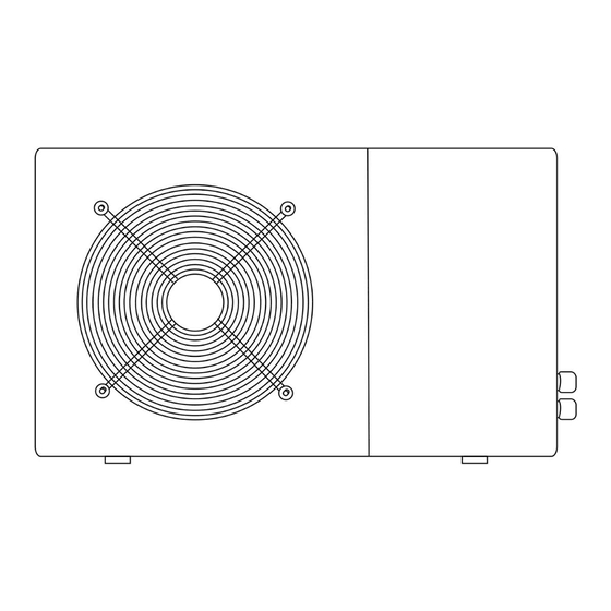
Page 7: Dimension (Mm)
2. Dimension (mm) Model Inverter 7 Model Inverter 11/14/16... - Page 8 Model Inverter 19 Model Inverter 24/24T/29/29T...
-
Page 9: Installation And Connection
3. Installation and connection 3.1 Notes The factory supplies only the heat pump. All other components, including a bypass if necessary, must be provided by the user or the installer. Attention: Please observe the following rules when installing the heat pump: 1. -
Page 10: Check-Valve Installation
groundwater level is high. A rough estimate of the heat loss per 30 m is 0.6 kWh (2,000 BTU) for every 5 ºC difference between the water temperature in the pool and the temperature of the soil surrounding the pipe. This increases the operating time by 3% to 5%. -
Page 11: Electrical Connection
3.6 Adjusting the bypass Use the following procedure to adjust the bypass: 1.Valve 1 wide open. Valve 2 & valve 3 closed. 2.Slowly open valve 2 & valve 3 by To pool From pool half, then close the valve 1 slowly to increase the water flow to valve 2 &... - Page 12 After all connections have been made and checked, carry out the following procedure: 1. Switch on the filter pump. Check for leaks and verify that water is flowing from and to the swimming pool. 2. Connect power to the heat pump and press the On/Off button on the electronic control panel.
- Page 13 4. Accessories 4.1 Accessories list Anti-vibration base, 4 pcs Draining jet, 2 pcs Waterproof box, 1 pc 10M Signal wire, 1 pc Water drainage pipes, 2 pcs 4.2 Accessories Installation Anti-vibration bases 1. Take out 4 Anti-vibration bases 2. Put them one by one on the bottom of machine like the picture.
- Page 14 Water Inlet & outlet junction 1. Use the pipe tape to connect the water Inlet & outlet junction onto the heat pump 2. Install the two joints like the picture shows 3. Screw them onto the water Inlet & outlet junction Cable wiring 1.
-
Page 15: Electrical Wiring
5. Electrical Wiring 5.1 SWIMMING POOL HEAT PUMP WIRING DIADRAM Inverter 7/11/14/16/19... - Page 16 5.2 SWIMMING POOL HEAT PUMP WIRING DIADRAM Inverter 24...
- Page 17 5.3 SWIMMING POOL HEAT PUMP WIRING DIADRAM Inverter 29...
- Page 18 5.4 SWIMMING POOL HEAT PUMP WIRING DIADRAM Inverter 24T/29T NOTE: (1)Above electrical wiring diagram only for your reference, please subject machine posted the wiring diagram. (2)The swimming pool heat pump must be connected ground wire well, although the unit heat exchanger is electrically isolated from the rest of the unit .Grounding the unit is still required to protect you against short circuits inside the unit .Bonding is also required.
-
Page 19: Display Controller Operation
5.5 Installation of the display deportee Photo(1) Photo(2) Photo(3) Photo(4) Photo(5) - The side with plug connects with the control panel (photo1) - The other side of the signal wire. (photo2) - Open the wiring panel and put the side without plug through the electrical box. (photo3,4) - Insert the wiring into the disignated position (code:COM 1 or COM-L) on the PC board. - Page 20 Press to stop the heat pump unit and show “OFF” Notice : During the parameter checking and setting, press the to quick-exit and save the current setting . Press again to turn on/off the machine. 6.2.2 button Automatic mode: Press for 5 seconds to switch to automatic mode.(default:Smart mode) Press for 5 seconds again to exit automatic mode and switch to heating mode(default:Smart mode)
- Page 21 Frequency limitation code 0,1,2,4,8,16 Real testing value Piping temp. -30℃~70℃ Real testing value Gas exhaust temperature 0℃~C5℃ (125℃) Real testing value Step of EEV 0~99 Compressor running frequency Real testing value 0~99Hz Compressor current 0~30A Real testing value Current fan speed 0-1200 (rpm)...
- Page 22 will be lighting at the same time. When there is on Automatic mode, 6.2.7 Symbol of automatic stop, the light will be on when it is in operation. will be flash. Note: When parameter P6 is on checking/adjusting, Symbol of automatic stop light 6.2.8 Symbol of automatic start, the light will be on when it is in operation.
-
Page 23: Troubleshooting
7. Troubleshooting 7.1 Error code display on LED wire controller Error Code Malfunction Reason Solution 1. High pressure switch in bad 1. Check the wiring for high pressure connection or failure switch or change a new one 2. Ambient temperature is too high High pressure 2.Check the water flow or water pump EE 01... - Page 24 phase sequence range 3. Compressor accumulations 4. Check phase sequence liquid and oil lead to the current connection becomes larger 4. Compressor driver board damaged 5. The water flow is abnormal 6. Power fluctuations within a short time 1. Check and re-connect the signal Communication wire 1.
- Page 25 1. Change a driver board 1. Output exception of IPM module 2. Check if the fan motor speed is too Temperature of IPM thermal circuit EE 15 low or fan motor damaged, change module is too high 2. Motor is abnormal or damaged another one 3.
- Page 26 1. Switch to Cooling mode to check 1. Four-way valve reversal failure the 4-way valve if it has been reversed Four-way valve EE 26 2. Lack of refrigerant (no detect correctly reversal failure when T3 or T5 malfunction) 2. Change a new 4-way valve 3.
-
Page 27: Setting Temperature
Remarks: 1. In heating mode, if the water out temperature is higher than the set temperature over 7℃, LED controller displays EE04 for water over-heating protection. 2. In cooling mode, if the water out temperature is lower than the set temperature over 7℃, LED controller displays PP11 for water over-cooling protection. - Page 28 Water pump running logic and error code ‘ON’. There are two options for water pump running. Option 1:Water pump starts or stops in relation to heat pump operation. Water pump starts 60s before compressor, water pump start 30s and then detect the water flow switch. When the heat pump enters standby mode, water pump will stop 60s after compressor stops.
- Page 29 7.2 Other Malfunctions and Solutions (No display on LED wire controller) Malfunctions Observing Reasons Solution LED wire controller Check cable and circuit No power supply no display. breaker if it is connected LED wire controller. Heat pump under standby Startup heat pump to run. displays the actual time.
-
Page 30: Exploded Diagram And Maintenance
8. Exploded Diagram and Maintenance 8. 1 Exploded Diagram Model Inverter 7... - Page 32 NO. Spare parts NO. Spare parts 1 Top cover 33 Transition pipe 2 Ambient temp. sensor 34 Pipe (Titanium exchanger to Capillary ) 3 Ambient temp. sensor clip 35 Capillary 4 Back grill 36 Low pressure switch 5 Evaporator 37 Exhaust temp. sensor 6 Coil temp.
- Page 33 Model Inverter 24...
- Page 35 Spare parts Spare parts Top cover Clip Ambient temp. sensor Terminal board Bracket Ambient temp. sensor clip Water pump 3-position terminal Back grill Terminal cover Evaporator Rubber fixing block Coil temp. sensor Gas colleting piping Temp. sensor clip Back panel Sensor casing pipe Back gas piping Distribution piping...
-
Page 36: Maintenance
9. Maintenance (1) You should check the water supply system regularly to avoid the air entering the system and occurrence of low water flow, because it would reduce the performance and reliability of HP unit. (2) Clean your pools and filtration system regularly to avoid the damage of the unit as a result of the dirty of clogged filter. -
Page 37: Warranty And Returns
10. Warranty and returns 10.1 Warranty LIMITED WARRANTY Thank you for purchasing a heat pump from us. This warranty covers manufacturing and material defects in all components for a period of two years after the date of purchase. This warranty is limited to the original purchaser in the retail sector. It is not transferable, and it is not applicable to products that have been removed from their original installation location. -
Page 38: Rma Request Form
10.2 RMA request form Company: Date: Street address: City/town: Postal Country: code: Contact: Phone: E-mail: Fax: Contact: Date: Reserved for internal use RMA no.: Assigned by: Date: Reason for return: Copy of customer invoice included? RMA request accompanied by other documents? Description of the documents: Model no.: Invoice no.:... - Page 39 All products received by us that lack labels or that have incorrect, incomplete or unreadable labels will be refused, with return shipping costs to be borne by you. All packages delivered to us with clearly visible damage will be refused immediately. Before returning products, please check that the products you intend to return to us are the same as the products for which an RMA number was issued.
Need help?
Do you have a question about the Hydro-Pro Inverter 11 and is the answer not in the manual?
Questions and answers