Table of Contents

Subscribe to Our Youtube Channel
Related Manuals for AES Remora Professional Series


Summary of Contents for AES Remora Professional Series
- Page 1 MANUAL POOL HEAT PUMP Remora Professional Inverter Swimming Pool Heat Pump Automated Environmental Systems Ltd., Unit B, Anglian Lane, Bury St Edmunds, Suffolk IP32 6SR 01842 819130 | sales@automatedenvironmentalsystems.co.uk...
-
Page 3: Table Of Contents
TABLE OF CONTENT 1. PREFACE …………...……………………………………………………………………………………………………..…………..2 2. CARTON CONTENTS …………...……………………………………..………………………………………………………..5 3. OVERVIEW OF THE UNIT …………………………………………………………………………………..……………….……6 4. INSTALLATION AND CONNECTION ………………………………………………..………..………..……………….……8 4.1 Installation Illustration ………….………………..………..………………………………………..……………….……8 4.2 Swimming Pool Heat Pumps Location ….…………..………………………………………..……………….……8 4.3 How Close to Your Pool? ….…………..…………………………………………………………..……………….……9 4.4 Swimming Pool Heat Pumps Plumbing ….………………………………………………..….…………….……9 4.5 Swimming Pool Heat Pumps Electrical Wiring …………………………………………..….………….…10 Initial Startup of the Unit ….………………..……….………………………………………………...……….…10 5. OPERATING THE UNIT ……………………………………………………………………………………………….…….……11 6. LCD CONTROLLER ……………………………………………………..……………………………………………….…….……12 6.1 LCD CONTROLLER INTERFACE ………..…..……..……………………………………………..……………….……12 6.2 KEYPAD LOCK / UNLOCK ….….…….……………………….…………………………………….……………….……14 6.3 MAIN RUNNING MODE SELECTION ….….……………………………….…………………..……………….……14 6.4 SUB‐RUNNING MODE SELECTION ….….……………..………………….…………………..……………….……14 6.5 SETTING THE TIMER ….…………………..…..……………………………………….…………..……………….……15 6.6 PARAMTER SETTING ….…………..……………………………….………………….…………..……………….……16 ... -
Page 4: Preface
1. PREFACE In order to provide our customers with quality, reliability and versatility, this product has been made to strict production standards. This manual includes all the necessary information about installation, debugging, discharging and maintenance. Please read this manual carefully before you open or maintain the unit. The manufacture of this product will not be held responsible if someone is injured or the unit is damaged, as a result of improper installation, debugging, or unnecessary maintenance. - Page 5 WARNING Do not use means to accelerate the defrosting process to clean, other than those recommended by the manufacturer. The appliance shall be stored in a room without continuously operating ignition sources (for example: open flames, an operating gas appliance or an operating electric heater.) Do not pierce or burn.
- Page 6 Caution & Warning 1. Please make sure that the unit and power connection have good earthing, otherwise may cause electrical shock. 2. Directive 2002/96/EC (WEEE): The symbol depicting a crossed-out waste bin that is underneath the appliance indicates that this product, at the end of its useful life, must be handled separately from domestic waste, must be taken to a recycling centre for electric and electronic devices or handed back to the dealer when purchasing an equivalent appliance.
-
Page 7: Carton Contents
2. CARTON CONTENTS Before starting the installation, please make sure that all following items are found inside the box. Carton Box Item Image Quantity Swimming pool heat pump Operation and Installation Manual Accessories 1 (Set) - 5 - Automated Environmental Systems Ltd., Unit B, Anglian Lane, Bury St Edmunds, Suffolk IP32 6SR 01842 819130 | sales@automatedenvironmentalsystems.co.uk... -
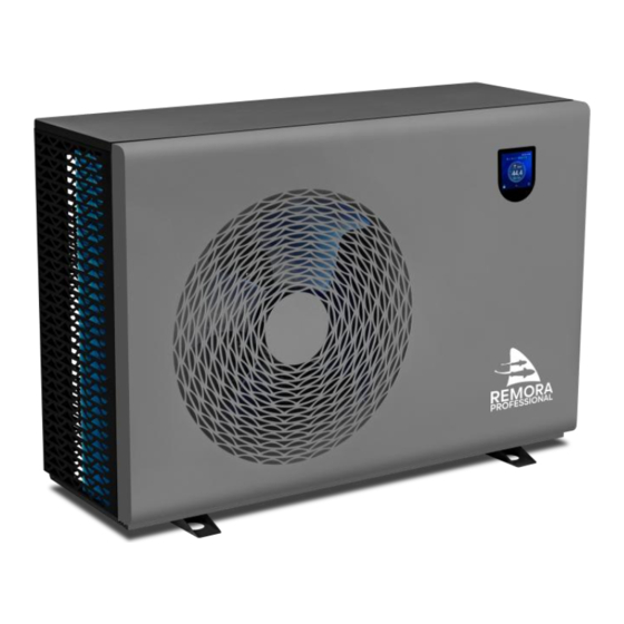
Page 8: Overview Of The Unit
3. OVERVIEW OF THE UNIT Remora Professional 8 Remora Professional 19 Remora Professional 10 Remora Professional 25 Remora Professional 14 1020 - 6 - Automated Environmental Systems Ltd., Unit B, Anglian Lane, Bury St Edmunds, Suffolk IP32 6SR 01842 819130 | sales@automatedenvironmentalsystems.co.uk... - Page 9 Remora Professional 35 1170 1389 1170 - 7 - Automated Environmental Systems Ltd., Unit B, Anglian Lane, Bury St Edmunds, Suffolk IP32 6SR 01842 819130 | sales@automatedenvironmentalsystems.co.uk...
-
Page 10: Installation And Connection
4. INSTALLATION AND CONNECTION ustration 4.1 Installation Ill Installation items: The factory only provides the main unit, the other items in the illustration are necessary spare parts for the water system, that provided by users or the installer. Attention: Please follow these steps when using for the first time 1. -
Page 11: How Close To Your Pool
DO NOT place the unit to shrubs which can block air inlet. These locations deny the unit of a continuous source of fresh air which reduces it efficiency and may prevent adequate heat delivery. 4.3 How Close To Your Pool? Normally, the pool heat pump is installed within 7.5 metres of the pool. -
Page 12: Swimming Pool Heat Pumps Electrical Wiring
Condensation: Since the Heat pump cools down the air about 4 -5 , water may condense on the fins of the horseshoe shaped evaporator. If the relative humidity is very high, this could be as much as several litres an hour. The water will run down the fins into the basepan and drain out through the barbed plastic condensation drain fitting on the side of the basepan. -
Page 13: Operating The Unit
5. OPERATING THE UNIT This is achieved via the Digital Controller. NEVER LET THE DIGITAL CONTROLLER GET WET. THIS MAY CAUSE AN ELECTRIC SHOCK OR FIRE. NEVER PRESS THE BUTTONS OF THE DIGITAL CONTROLLER WITH A HARD, POINTED OBJECT. THIS MAY DAMAGE THE DIGITAL CONTROLLER. -
Page 14: Lcd Controller
6. LCD CONTROLLER Control Panel Interface Icon Name Function Anti-freeze This icon will show if heat pump goes into Anti-freeze mode, and it will show in Grey once Anti-freeze exits. Defrost This icon will show if heat pump goes into Defrost mode, and it will show in Grey once Defrost exists. - Page 15 Icon Name Function Main running This icon will indicate the actual main running mode of the unit. mode selection (Heating/ Cooling/ Auto modes for options). Sub-running This icon will indicate the actual sub-running mode of the unit. Boost mode selection (Boost/ Silent/ Eco/ Smart sub-modes for options).
-
Page 16: Keypad Lock / Unlock
6.2 Keypad Lock / Unlock Indicates the keypad is unlocked, press it to lock the keypad. Indicates the kepad is locked, press it to unlock the keypad. 6.3 Main Running Mode Selection On the main operation interface, press the place at to enter into main running mode selection and set target water temperature. -
Page 17: Setting The Timer
6.5 Setting the Timer On the second page of main operation interface, press to enter into Timer setting interface. Activate or Deactivate each Timer settings from the right sliding block. (Activated in BLUE, and Deactivate in GREY.) Press to enter into Timer setting interface. -
Page 18: Paramter Setting
6.6 Parameter Setting Press to enter Parameter Settings into Input Password: 223344 to enter to set Parameter values. - 16 - Automated Environmental Systems Ltd., Unit B, Anglian Lane, Bury St Edmunds, Suffolk IP32 6SR 01842 819130 | sales@automatedenvironmentalsystems.co.uk... - Page 19 Code Parameter Name Default Range Cool mode water temperature differential to restart 1~10 Heat mode water temperature differential to restart 1~10 Main water pump P1P5 mode 0、1、2 Water pump running time in standby mode 1~30 Water pump stopping time in standby mode 3~240 TA temp display deviation -3~3...
-
Page 20: Running Status Query
6.7 Running Status Query Press to enter status query into Press to navigate different pages. - 18 - Automated Environmental Systems Ltd., Unit B, Anglian Lane, Bury St Edmunds, Suffolk IP32 6SR 01842 819130 | sales@automatedenvironmentalsystems.co.uk... - Page 21 Parameter Name Value or Status Compressor frequency Actual value Fan speed Actual value EXV1 opening angle Actual value EXV3 opening angle Actual value TP compressor exhaust gas temp Actual value T3 coil temp Actual value T4 ambient temp Actual value TL liquid coil temp Actual value TJ EVI PHE outlet temp...
- Page 22 Main water pump P1 ON;OFF SV1 by-pass valve status ON;OFF Inverter compressor heat belt HT1 ON;OFF Chassis heat belt HT2 ON;OFF Electric heater H1 ON;OFF High pressure switch ON;OFF Low pressure switch ON;OFF ON ;OFF Flow switch FS External control Pump signal status ON;OFF External control signal status ON;OFF...
-
Page 23: Check Power Consumption
6.8 Check Power Consumption Press “ ” on the screen to find out running time and how much electricity consumption (kW.h) in every mode. 6.9 Fault History Press “ ” on the screen. Press navigate different pages. - 21 - Automated Environmental Systems Ltd., Unit B, Anglian Lane, Bury St Edmunds, Suffolk IP32 6SR 01842 819130 | sales@automatedenvironmentalsystems.co.uk... -
Page 24: Vacation Setting
6.10 Vacation Setting HERE turn ON or OFF the “ Vacation Setting ” on the screen below. Press to enter Vacation Setting. into Press the line Press the line under under “Start Time”. “End Time”. - 22 - Automated Environmental Systems Ltd., Unit B, Anglian Lane, Bury St Edmunds, Suffolk IP32 6SR 01842 819130 | sales@automatedenvironmentalsystems.co.uk... -
Page 25: Timer Set For Silent Mode
6.11 Timer Set for Silent Mode Press “ ” on the screen. 6.12 Help Press “ ” on the screen. Press to navigate different pages. - 23 - Automated Environmental Systems Ltd., Unit B, Anglian Lane, Bury St Edmunds, Suffolk IP32 6SR 01842 819130 | sales@automatedenvironmentalsystems.co.uk... -
Page 26: Error Codes
7. ERROR CODES Error Failure Heat Pump Action Remedy Code Check whether the inverter System shutdown, fault IPM overcurrent fault compressor and IPM module board reported are damaged. AC overvoltage / Check whether the power supply is System shutdown, fault undervoltage normal, and check the outdoor reported... - Page 27 System shutdown, fault Check whether the fan motor and Fan failure reported outdoor PCB are damaged. TH suction gas temp System shutdown, fault Check TH suction gas temp sensor sensor failure reported and outdoor PCB. System shutdown, fault Driver EE failure Check drive board.
- Page 28 High outlet water temp System shutdown, fault Check water pump and outdoor protection in heat reported PCB. mode Low outlet water temp System shutdown, fault Check water pump and outdoor protection in cool mode reported PCB. TL Liquid coil temp System shutdown, fault Check TL liquid coil temp sensor sensor failure...
- Page 29 AC current limiting Normal protection frequency T3 coil temp limiting Normal protection frequency Tp exhaust gas temp Normal protection limiting frequency Compressor current Normal protection limiting frequency IPM temp limiting Normal protection frequency - 27 - Automated Environmental Systems Ltd., Unit B, Anglian Lane, Bury St Edmunds, Suffolk IP32 6SR 01842 819130 | sales@automatedenvironmentalsystems.co.uk...
-
Page 30: Maintenance And Inspection
8. MAINTENANCE AND INSPECTION Check the water supply device and release often. You should avoid the condition of no water or air entering into system, as this will influence unit's performance and reliability.You should clear the pool/spa filter regularly to avoid damage to the unit as a result of the dirty of clogged filter. ... - Page 31 be kept sufficiently far away from the site of installation, repairing, removing and disposal, during which flammable refrigerant can possibly be released to the surrounding space. Prior to work taking place, the area around the equipment is to be surveyed to make sure that there are no flammable hazards or ignition risks.
- Page 32 Repairs to sealed components 1) During repairs to sealed components, all electrical supplies shall be disconnected from the equipment being worked upon prior to any removal of sealed covers, etc. If it is absolutely necessary to have an electrical supply to equipment during servicing, then a permanently operating form of leak detection shall be located at the most critical point to warn of a potentially hazardous situation.
- Page 33 area.) . Ensure that the detector is not a potential source of ignition and is suitable for the refrigerant used. Leak detection equipment shall be calibrated to the refrigerant employed and the appropriate percentage of gas (25 % maximum) is confirmed. Leak detection fluids are suitable for use with most refrigerants but the use of detergents containing chlorine shall be avoided as the chlorine may react with the refrigerant and corrode the copper pipe- work.
- Page 34 Labelling Equipment shall be labelled stating that it has been de-commissioned and emptied of refrigerant. The label shall be dated and signed. Ensure that there are labels on the equipment stating the equipment contains flammable refrigerant. Recovery When removing refrigerant from a system, either for servicing or decommissioning, it is recommended good practice that all refrigerants are removed safely.
- Page 35 . The recovery process is supervised at all times by a competent person. . Recovery equipment and cylinders conform to the appropriate standards. d) Pump down refrigerant system, if possible. e) If a vacuum is not possible, make a manifold so that refrigerant can be removed from various parts of the system.
-
Page 36: Wiring Diagrams
9. WIRING DIAGRAMS Please refer to the wiring diagram on the electric box. Models: Remora Professional 8, Remora Professional 10, Remora Professional 14, Remora Professional 19, Remora Professional 25 CN15 - 34 - Automated Environmental Systems Ltd., Unit B, Anglian Lane, Bury St Edmunds, Suffolk IP32 6SR 01842 819130 | sales@automatedenvironmentalsystems.co.uk... - Page 37 Models: Remora Professional 35 FAN2 (BLK for 33KW) FAN1 AC-N AC-L PFC + IPM board COM1 Reactor1 Reactor2 Evaporator coil temp. Condenser coil temp. Ambient temp. Outlet water temp. Return temp. AC-L1 Inlet water temp. Exhaust temp . AC-L2 ARTH Water flow Switch IM1275 High Pressure Switch...
-
Page 38: Cable Specification
10. CABLE SPECIFICATION The Electrical supply must correspond to that indicated on the appliance. All supply cables have to be sized according to the appliance power and installation requirements. Please refer to table below: Heat Pump Model Cable Size 3 x 2.0mm Remora Professional 8, Remora Professional 10 3 x 2.5mm Remora Professional 14... - Page 39 NOTES - 37 - Automated Environmental Systems Ltd., Unit B, Anglian Lane, Bury St Edmunds, Suffolk IP32 6SR 01842 819130 | sales@automatedenvironmentalsystems.co.uk...
Need help?
Do you have a question about the Remora Professional Series and is the answer not in the manual?
Questions and answers