
Related Manuals for AES hydro-pro PX


Summary of Contents for AES hydro-pro PX
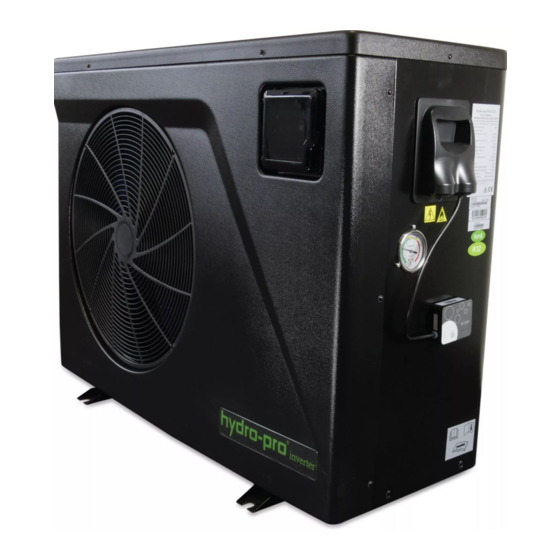
- Page 1 INVERTER TYPE PX SWIMMING POOL HEAT PUMP UNIT Installation & Instruction Manual SALES & SERVICE 01842 819130...
-
Page 2: Table Of Contents
CONTENTS 1. Preface 2. Specifications 2.1 Performance Data of Swimming Pool Heat Pump Unit 2.2 Dimensions for Swimming Pool Heat Pump Unit 3. Installation and Connection Installation illustration Swimming Pool Heat Pumps Location 3.3 How Close to Your Pool? 3.4 Swimming Pool Heat Pumps Plumbing 3.5 Swimming Pool Heat Pumps Electrical Wiring 3.6 Initial Start-up of the Unit Use and Operation Instruction... -
Page 3: Preface
1. PREFACE In order to provide our customers with quality, reliability and versatility, this product has been made to strict production standards. This manual includes all the necessary information about installation, debugging, discharging and maintenance. Please read this manual carefully before you open or maintain the unit. The manufacture of this product will not be held responsible if someone is injured or the unit is damaged, as a result of improper installation, debugging, or unnecessary maintenance. - Page 4 1. PREFACE This appliance can be used by children aged from 8 years and above and persons with reduced physical, sensory or mental capabilities or lack of experience and knowledge if they have been given supervision or instruction concerning use of the appliance in a safe way and understand the hazards involved.
- Page 5 1. PREFACE Caution & Warning 1. The unit can only be repaired by qualified installer centre personnel or an authorised dealer.(for Europe market) 2. This appliance is not intended for use by persons (including children) with reduced physical sensory or mental capabilities, or lack of experience and knowledge, unless they have been given supervision or instruction concerning use of the appliance by a person responsible for their safety.
-
Page 6: Specifications
2.SPECIFICATION 2.1 Performance data of Swimming Pool Heat Pump Unit *** REFRIGERANT : R32 Hydro-Pro Inverter PX14/32 PX7/32 PX11/32 MODEL Part nr. 7028285 7028283 7028284 Heating capacity A27/W27 (max.-min.) 14-2.52 7.24-1.82 11-2.23 Heating capacity A15/W25 (max.-min.) 7.9-1.58 9.5-1.79 5.64-1.39 Power input (max.-min.) 2.15-0.16 1.8-0.13 2.05-0.15... - Page 7 2.SPECIFICATION 2.1 Performance data of Swimming Pool Heat Pump Unit *** REFRIGERANT : R32 Hydro-Pro Inverter PX17/32 PX21/32 MODEL Part nr. 7028286 7028287 Heating capacity A27/W27 (max.-min.) 16-3.25 19-3.5 Heating capacity A15/W25 (max.-min.) 12.6-2.55 14-2.55 Power input (max.-min.) 3.7-0.22 3.8-0.25 Swimming pool volume* 45-80 55-95...
- Page 8 2.SPECIFICATION 2.1 Performance data of Swimming Pool Heat Pump Unit *** REFRIGERANT : R32 Hydro-Pro Inverter PX25/32 PX25T/32 MODEL Part nr. 7028288 7028289 Heating capacity A27/W27 (max.-min.) 25.5-5.7 25.5-5.7 Heating capacity A15/W25 (max.-min.) 18.6-4.68 18.6-4.68 Power input (max.-min.) 5.24-0.35 6.78-0.35 Swimming pool volume* 75-130 75-130...
- Page 9 2.SPECIFICATION 2.1 Performance data of Swimming Pool Heat Pump Unit *** REFRIGERANT : R32 Hydro-Pro Inverter PX30/32 PX30T/32 MODEL Part nr. 7028290 7028291 Heating capacity A27/W27 (max.-min.) 30-6.7 30-6.7 Heating capacity A15/W25 (max.-min.) 23.7-5.46 23.7-5.46 Power input (max.-min.) 7.22-0.42 7.35-0.42 Swimming pool volume* 100-175 100-175...
-
Page 10: Dimensions For Swimming Pool Heat Pump Unit
2.SPECIFICATION 2.2 The dimensions for Swimming Pool Heat Pump Unit Model:PX7/32 unit:mm PX11/32 PX14/32 1000 Water outlet Φ50 Water inlet Φ50 Model:PX17/32 unit:mm 1046 Water outlet Φ50 Water inlet Φ50... - Page 11 2.SPECIFICATION 2.2 The dimensions for Swimming Pool Heat Pump Unit Model:PX21/32 unit:mm 1160 Water outlet Φ50 Water inlet Φ50 Models: PX25/32 unit:mm PX25T/32 PX30/32 1161 PX30T/32 Water outlet Φ50 Water inlet Φ50...
-
Page 12: Installation And Connection
3.INSTALLATION AND CONNECTION 3.1 Installation illustration Valve Water outlet Chlorinator cell Water supply Pool Water inlet Sand filter Water pump (or other type filter) Installation items: The factory only provides the main unit and the water unit; the other items in the illustration are necessary spare parts for the water system ,that provided by users or the installer. -
Page 13: Swimming Pool Heat Pumps Location
3.INSTALLATION AND CONNECTION 3.2 Swimming Pool Heat Pumps Location The unit will perform well in any outdoor location provided that the following three factors are presented: 1. Fresh Air - 2. Electricity - 3. Pool filter piping The unit may be installed virtually anywhere outdoors. For indoor pools please consult the supplier. -
Page 14: Swimming Pool Heat Pumps Plumbing
3.INSTALLATION AND CONNECTION 3.4 Swimming Pool Heat Pumps Plumbing The Swimming Pool Heat Pumps exclusive rated flow titanium heat exchanger requires no special plumbing arrangements except bypass(please set the flow rate according to the nameplate). The water pressure drop is less than 10kPa at max. Flow rate. Since there is no residual heat or flame Temperatures, The unit does not need copper heat sink piping. -
Page 15: Swimming Pool Heat Pumps Electrical Wiring
3.INSTALLATION AND CONNECTION 3.5 Swimming Pool Heat Pumps Electrical Wiring NOTE: Although the unit heat exchanger is electrically isolated from the rest of the unit, it simply prevents the flow of electricity to or from the pool water. Grounding the unit is still required to protect you against short circuits inside the unit. -
Page 16: Use And Operation Instruction
4.Use and Operation Instruction 4.1.Interface display 4.2.Key and icon function instruction 2.1 Key function instruction Key symbols Function Designation Under the heating mode or heating mode under the automatic mode, the mute key operation is effective and Mute key used to enter and exit the mute mode with one click. It is used to switch the unit mode, temperature setting, Mode key and parameter setting. - Page 17 4.Use and Operation Instruction 2.2.Icon function instruction Function Icon symbol Designation It will display during cooling (there is no limit to startup & Cooling shutdown, and it is optional when the unit is cooling-only symbol unit or heating-and-cooling unit). It will display during heating (there is no limit to startup & Heating shutdown, and it is optional when the unit is heating-only symbol...
-
Page 18: Startup & Shutdown
4.Use and Operation Instruction 4. 3. Startup & shutdown Keep long press of " "for 0.5 s to enter ON/OFF interface When there is no operation within 1 minute, it will display with half screen off When there is no operation within 15 minutes, it will display with full screen off Notes:... -
Page 19: Temperature Setting
4.Use and Operation Instruction Cooling mode Heating mode Short press" " for to switch the mode circularly, after no operation for 2s, the current mode will be saved. Automatic mode Operation descriptions: 1). Mode switch operation can only be conducted in the main interface. 2). -
Page 20: Clock Setting
4.Use and Operation Instruction 4.6. Clock setting 6.1 System time setting Long press " " for 2 s to enter into the system times Short press " " setting interface Hour digit flashing System time setting Press " " or "... - Page 21 4.Use and Operation Instruction 6.2.3 Setting the Timer ON/OFF function OFF1 While enter into the timer setting interface , set the Timer ON/OFF as below: " " " " " " " " * Take for example: Press " "or " "...
-
Page 22: Silent Setting
4.Use and Operation Instruction 4.7. Silent setting 7.1 One-click silent function short press " " Flashing Notes: 1). If one-click silent and timming silentaare stared at the same time, short press " " for canceling one-click silent and quitting the timing silent for this time. 2). -
Page 23: Keyboard Lock
4.Use and Operation Instruction Notes: 1). When the silent icon" " is lighten:The timing mute has been set, but it's not under silent status. 2). When the silent icon" " flash:It's under the silent status. 3). When the silent icon" "disappear: The timingsilent is not set. -
Page 24: Parameter List And Breakdown Table
4.Use and Operation Instruction 4.10 . Parameter list and breakdown table 10.1 Electronic control fault table Can be judged according to the remote controller failure code and troubleshooting Fault Protect/fault Reason Elimination methods display The temp. Sensor is broken Inlet Temp. Sensor Fault Check or change the temp. - Page 25 4.Use and Operation Instruction 1. Motor is in locked-rotor state 1.Change a new fan motor 2.The wire connection between 2.Check the wire connection and make sure Fan Motor2 Fault F032 DC-fan motor module and fan they are in good contact motor is in bad contact Communication Fault Speed control module and main...
-
Page 26: Interface Drawin
4.Use and Operation Instruction 10.2 Parameter list Meaning Remarks Default Adjustable Refrigeration target temperature set point 27℃ Adjustable Heating the target temperature set point 27℃ Automatic target temerature set point Adjustable 27℃ 4.11 Interface drawin (1) Wire control interface diagram and definition Sign Meaning 12V(power +)... - Page 27 4.OPERATION AND USE Main board of the input and output interface instructions below Number Sign Meaning OUT1 Compressor ( output 220-230VAC) OUT2 Water pump ( output 220-230VAC) OUT3 4-way valve ( output 220-230VAC) OUT4 High speed of fan ( output 220-230VAC) OUT5 Low speed of fan (output 220-230VAC)...
-
Page 28: Main Board
4.Use and Operation Instruction 4.12 . Main board(PIV7/32 PIV11/32 PIV14/32) Controller interface diagram and definition... - Page 29 4.Use and Operation Instruction 4.11 . Main board(PIV17/32 PIV21/32) Controller interface diagram and definition...
- Page 30 4.Use and Operation Instruction Main board of the input and output interface instructions below Number Sign Meaning P10-(U) P10-(V) Compressor ( output 220-230VAC) P10-(W) CN18(EMV) Water pump ( output 220-230VAC) CN13(HEAT) 4-way valve ( output 220-230VAC) CN96(H) High speed of fan ( output 220-230VAC) CN96(L) Low speed of fan (output 220-230VAC)...
-
Page 31: Maintenance And Inspection
5. MAINTENANCE AND INSPECTION Check the water supply device and the release often. You should avoid the condition of no water or air entering into system, as this will influence unit's performance and reliability. You should clear the pool/spa filter regularly to avoid damage to the unit as a result of the dirty of clogged filter. - Page 32 5. MAINTENANCE AND INSPECTION No ignition sources No person carrying out work in relation to a refrigeration system which involves exposing any pipe work that contains or has contained flammable refrigerant shall use any sources of ignition in such a manner that it may lead to the risk of fire or explosion. All possible ignition sources, including cigarette smoking, should be kept sufficiently far away from the site of installation, repairing, removing and disposal, during which flammable refrigerant can possibly be released to the surrounding space.
- Page 33 5. MAINTENANCE AND INSPECTION 5. MAINTENANCE AND INSPECTION Repairs to sealed components 1) During repairs to sealed components, all electrical supplies shall be disconnected from the equipment being worked upon prior to any removal of sealed covers, etc. If it isabsolutely necessary to have an electrical supply to equipment during servicing, then a permanently operating form of leak detection shall be located at the most critical point to warn of a potentially hazardous situation.
- Page 34 5. MAINTENANCE AND INSPECTION 5. MAINTENANCE AND INSPECTION Removal and evacuation When breaking into the refrigerant circuit to make repairs or for any other purpose conventional procedures shall be used. However, it is important that best practice is followed since flammability is a consideration. The following procedure shall be adhered to: .
- Page 35 5. MAINTENANCE AND INSPECTION 5. MAINTENANCE AND INSPECTION Decommissioning Before carrying out this procedure, it is essential that the technician is completely familiar with the equipment and all its detail. It is recommended good practice that all refrigerants are recovered safely. Prior to the task being carried out, an oil and refrigerant sample shall be taken in case analysis is required prior to re-use of reclaimed refrigerant.
-
Page 36: Appendix
6.APPENDIX 6.1 Cable specification (1) Single phase unit Nameplate Creepage protector Signal line maximum Phase line Earth line current No more 2×1.5mm 1.5mm 30mA less than 0.1 sec than 10A 2×2.5mm 2.5mm 30mA less than 0.1 sec 10~16A 2×4mm 30mA less than 0.1 sec 16 ~25A 2×6mm 25 ~32A... -
Page 37: Comparison Table Of Refrigerant Saturation Temperature
6.APPENDIX 6.2 Comparison table of refrigerant saturation temperature Pressure (MPa ) Temperature -51.3 (R410A)(℃) Temperature -52.5 29.5 33.3 38.7 (R32)(℃) Pressure (MPa ) Temperature (R410A)(℃) Temperature 46.5 49.5 53.5 67.5 72.5 77.4 (R32)(℃) - Page 38 Code:...
Need help?
Do you have a question about the hydro-pro PX and is the answer not in the manual?
Questions and answers